
Related Manuals for SolaX Power X1-Lite LV Series


Summary of Contents for SolaX Power X1-Lite LV Series
- Page 1 X1-Lite-LV 8 kW / 10 kW / 12 kW User Manual Version 0.0 www.solaxpower.com eManual in the QR code or at http://kb.solaxpower.com/...
- Page 2 No part of this manual may be reproduced, transmitted, transcribed, stored in a retrieval system, or translated into any language or computer language, in any form or by any means without the prior written permission of SolaX Power Technology (Zhejiang) Co., Ltd. Trademarks and other symbol or design (brand name, logo) that distinguishes the products or services offered by SolaX has been trademark protected.
- Page 3 About This Manual Scope of Validity This manual is an integral part of X1-Lite-LV series inverter. It describes the transportation, storage, installation, electrical connection, commissioning, maintenance and troubleshooting of the product. Please read it carefully before operating. This manual is valid for the following inverter models: •...
- Page 4 Conventions The symbols that may be found in this manual are defined as follows. Symbol Description Indicates a hazardous situation which, if not avoided, DANGER will result in death or serious injury. Indicates a hazardous situation which, if not avoided, WARNING could result in death or serious injury.
-
Page 5: Table Of Contents
Table of Contents Safety ......................1 1.1 General Safety ........................1 1.2 Safety Instructions of PV, Inverter, Grid and Battery ..........2 1.2.1 Safety Instructions of PV ..................2 1.2.2 Safety Instructions of Inverter ................3 1.2.3 Safety Instructions of Utility Grid ..............4 1.2.4 Safety Instructions of Battery ................4 Product Overview ..................5 2.1 Product Introduction ......................5 2.2 Appearance .........................5... - Page 6 6.1 Unpacking ..........................25 6.2 Scope of Delivery.......................26 Mechanical Installation ................28 7.1 Dimensions for mounting ....................29 7.2 Installation procedures.....................30 Electrical Connection ................33 8.1 Terminals of Inverter ......................34 8.2 PE Connection ........................35 8.3 EPS, GEN and GRID Connection ..................37 8.4 PV Connection ........................44 8.5 Battery Power Cable Connection .................48 8.6 COM Communication Connection ................54 8.6.1 Pin Assignment of COM Terminal ..............54...
- Page 7 Operation on SolaX App and Web ............93 11.1 Introduction of SolaXCloud ....................93 11.2 Operation Guide on SolaXCloud App .................93 11.2.1 Downloading and installing App ..............93 11.2.2 Operation on the App ..................94 11.3 Operations on SolaXCloud Webpage ................94 Troubleshooting and Maintenance ............95 12.1 Power off ..........................95 12.2 Troubleshooting .........................95 12.3 Maintenance ........................106...
-
Page 8: Safety
Safety General Safety The series inverter has been meticulously designed and thoroughly tested to comply with the relevant state and international safety standards. Nevertheless, like all electrical and electronic equipment, safety precautions must be observed and followed during the installation of the inverter to minimize the risk of personal injury and ensure a safe installation. -
Page 9: Safety Instructions Of Pv, Inverter, Grid And Battery
Safety Safety Instructions of PV, Inverter, Grid and Battery Save these important safety instructions. Failure to follow these safety instructions may result in damage to the inverter and injury or even loss of life. 1.2.1 Safety Instructions of PV DANGER! Potential risk of lethal electric shock associated with the photovoltaic (PV) system •... -
Page 10: Safety Instructions Of Inverter
Safety 1.2.2 Safety Instructions of Inverter DANGER! Potential risk of lethal electric shock associated with the inverter • Only operate the inverter if it is in a technically faultless condition. Operating a faulty inverter may lead to electric shock or fire. •... -
Page 11: Safety Instructions Of Utility Grid
CAUTION! • Make sure that children are supervised to prevent them from playing with the inverter. • Pay attention to the weight of the inverter and handle it properly to avoid personal injuries. NOTICE! • If an external Residual Current Device (RCD) is required by local regulations, verify the type of RCD required. -
Page 12: Product Overview
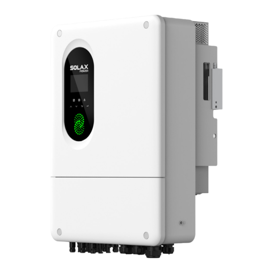
Product Overview Product Overview Product Introduction The X1-Lite-LV series inverter is an energy storage PV grid-connected inverter. It supports various intelligent solutions to achieve efficient and economical energy utilization. Appearance Nameplate LCD panel DC switch Electrical connection area Figure 2-1 Appearance Table 2-1 Description of appearance Item Description... -
Page 13: Supported Power Grid
Product Overview Supported Power Grid There are different ways of wiring for different grid systems. TT / TN-S / TN-C-S are shown as below: Figure 2-2 Supported power grid-TT TN-S Figure 2-3 Supported power grid-TN-S TN-C-S Figure 2-4 Supported power grid-TN-C-S... -
Page 14: Symbols On The Label And Inverter
Product Overview Symbols on the Label and Inverter Table 2-2 Description of symbols Symbol Description CE mark. The inverter complies with the requirements of the applicable CE guidelines. TUV certified. RCM mark. The inverter complies with the requirements of the applicable RCM guidelines. -
Page 15: Working Principle
Product Overview Working Principle 2.5.1 Circuit Diagram The inverter is equipped with multi-channel MPPT for DC input to ensure maximum power even under different photovoltaic input conditions. The inverter unit converts direct current into alternating current that meets the requirements of the power grid and feeds it into the power grid. -
Page 16: Application Schemes
Product Overview 2.5.2 Application Schemes Battery PV Module DC Breaker PV 1/2 PV 3/4 X1-Lite-LV PV 5/6 GRID Grid L N PE PE N L AC Breaker AC Breaker AC Breaker E-BAR Diesel Generator (To be released in quarter 4) Critical Loads Normal Loads Figure 2-6 Partial home backup for most countries... -
Page 17: Working State
Product Overview Working State The series inverter has INIT, IDLE, START, RUN and STOP state. Table 2-3 Description of working state State Description • The inverter is checking for the initialization information such INIT as the model and country, the conditions to be met in order to enter IDLE state. -
Page 18: Working Mode
Product Overview Working mode There are different work modes of the inverter based on different needs. Applicable areas Work modes Countries other than Pakistan (including Self consumption mode , backup mode and India, Vietnam, South Africa, Uzbekistan) Force time use mode SUB mode, SBU mode , MKS mode and Force Pakistan time use mode... -
Page 19: Backup Mode
Product Overview 2.7.2 Backup Mode This mode is applicable to countries other than Pakistan . Application Scenarios: This mode uses the energy storage system as a backup power source and is suitable for applications where power outages are frequent. When the grid is normal, the load is powered by solar and the grid, and the battery is only charged without discharging. -
Page 20: Force Time Use Mode
Product Overview 2.7.3 Force time use mode This mode is applicable to all countries including Pakistan . Application Scenarios: This mode is more suitable for applications with peak and off-peak electricity price differences. When the electricity price is high, the battery discharges to power the load. When the electricity price is low, the battery is charged from solar or the grid to reach full capacity. -
Page 21: Sbu Mode
Product Overview Note: In this mode, if the priority setting for the battery charging source is as follows: Only Solar Charging: No response, and the normal operation mode described above is followed. Solar then Utility Charging: If solar power is available, the battery is exclusively charged by solar. -
Page 22: Mks Mode
Product Overview 2.7.6 MKS Mode This mode is applicable under Pakistan's safety. Application Scenarios: This mode is suitable for customers who have higher electricity consumption during certain periods of the day and lower consumption at night. When solar power is available, this mode is basically the same as the SBU mode, and the discharge range of the battery is wider than that of the SBU mode. -
Page 23: System Overview
System Overview System Overview System Overview X1-Lite-LV Solax Cloud Communication Critical Loads Normal Loads Grid Diesel Generator Battery (To be released in quarter 4) Figure 3-1 System diagram Table 3-1 System item description Item Description X1-Lite-LV series inverter (the device The X1-Lite-LV series inverter is an energy storage inverter that covered in this supports grid connection of photovoltaic system. - Page 24 System Overview Item Description SolaX PV-Genset solution ensures optimum interaction between Generator the photovoltaics and diesel generator, which saves fuel, lowers (To be released in energy costs and ensures a stable and reliable power supply. quarter 4) 220 V / 230 V and 240 V grid are supported. Grid SolaX Cloud is an intelligent, multifunctional monitoring platform that can be accessed either remotely or through a hard wired...
-
Page 25: Transportation And Storage
Transportation and Storage Transportation and Storage If the inverter is not put into use immediately, the transportation and storage requirements needs to be met: Transportation • Observe the caution signs on the packaging of inverter before transportation. • Pay attention to the weight of the inverter. Carry the inverters by the required number of personnel as specified by local regulations.(gross/net weight of X1- Lite-LV: 42/37 kg) •... -
Page 26: Preparation Before Installation
Preparation before Installation Preparation before Installation Selection of Installation Location The installation location selected for the inverter is quite critical in the aspect of the guarantee of machine safety, service life and performance. It has the IP65 ingress protection, which allows it to be installed outdoor. The installation position shall be convenient for wiring connection, operation and maintenance. - Page 27 Preparation before Installation NOTICE! • For outdoor installation, precautions against direct sunlight,.rain exposure and snow accumulation are recommended. • Exposure to direct sunlight raises the temperature inside the device. This temperature rise poses no safety risks, but may impact the device performance. •...
-
Page 28: Installation Carrier Requirement
5.1.2 Installation Carrier Requirement The installation carrier must be made of a non-flammable material, such as solid brick, concrete, etc. and be capable of supporting the weight of the inverter and suitable of the dimensions of the inverter . If the wall strength is not enough (such as wooden wall, the wall covered by thick layer of decoration), it must be strengthened additionally. - Page 29 Preparation before Installation ≥35 cm ≥35 cm ≥60 cm ≥35 cm ≥35 cm ≥100 cm ≥100 cm ≥60 cm ≥35 cm ≥35 cm ≥120 cm ≥120 cm Multiple inverters Figure 5-5 Clearance requirement for multiple inverters...
-
Page 30: Tools Requirement
Preparation before Installation Tools Requirement Installation tools include but are not limited to the following recommended ones. If necessary, use other auxiliary tools on site. Please note that the tools used must comply with local regulations. Hammer drill Multimeter (drill bit: Ø10 mm) Measuring tape Utility knife (≥... -
Page 31: Additionally Required Materials
Additionally Required Materials Table 5-1 Additionally required wires Conductor Required Material Type Cross-section Dedicated PV wire with a voltage PV wire 4-6 mm² rating of 600 V Communication Network cable CAT5E 0.2 mm² wire Battery power Conventional copper wire 35~50 mm² cable Additional PE Conventional yellow and green... - Page 32 Table 5-4 Wire and breaker recommended for GEN connection Model 15 kW 20 kW 25 kW Wire 10 mm² 16 mm² 16 mm² (copper) Circuit 60 A 80 A 100 A breaker...
-
Page 33: Unpacking And Inspection
Unpacking and Inspection Unpacking and Inspection Unpacking • The inverter undergoes 100% testing and inspection before delivery. However, damages may still occur during transportation. Before unpacking, please carefully check the external packaging for any signs of damage, such as punctures or cracks. -
Page 34: Scope Of Delivery
Unpacking and Inspection Scope of Delivery Negative PV connector Positive PV connector Inverter Bracket & PV pin contact & PV pin contact Battery connection terminal Battery temperature Disassembling tool Y terminal OT terminal sensor for PV terminal Washer RJ45 terminal Expansion tube RJ45 connector M4*L12 screw... - Page 35 Unpacking and Inspection Item Description Quantity Remark For measuring the tem- Battery temperature sensor 1 pc perature of battery Disassembling tool for PV 1 pc terminal Battery connection terminal 4 pcs For Grid, EPS, GEN con- Y terminal 9 pcs nection OT terminal 1 pc...
-
Page 36: Mechanical Installation
Mechanical Installation Mechanical Installation WARNING! • Only qualified personnel are allowed to perform the mechanical installation following local laws and regulations. • Check the existing power cables or other piping in the wall to prevent electric shock or other damage. •... -
Page 37: Dimensions For Mounting
Dimensions for mounting Before installation, check the dimensions of the wall mounting bracket and ensure that enough space is reserved for the installation and heat dissipation of the entire system. Figure 7-3 Dimensions 1 (Unit: mm) Figure 7-4 Dimensions 2 (Unit: mm) -
Page 38: Installation Procedures
Mechanical Installation Installation procedures Step 1: Horizontally align the wall mounting bracket with the wall, adjust the position of the bracket with a spirit level until the bubble stays in the middle, and then mark holes. The minimum distance between the ground and the inverter is 1200 mm. 374 mm Figure 7-5 Marking the holes Step 2: Set the wall mounting bracket aside and drill holes with Ø10 drill bit. - Page 39 Mechanical Installation 1.5±0.1 N·m Figure 7-8 Securing the wall mounting bracket Step 4: If the inverter needs to be temporarily placed on the ground, use foam or other protective materials to protect it against potential damages. Lift up the inverter collaboratively by the required number of personnel in accordance with the local regulation and hang it onto the wall mounting bracket.
- Page 40 Step 5: Use M4*12 screws to secure the inverter on both sides. M4*L12 1.5±0.1 N·m Figure 7-11 Securing the inverter...
-
Page 41: Electrical Connection
Electrical Connection Electrical Connection DANGER! • Before electrical connection, make sure the DC switch and AC breaker are disconnected. Otherwise, the high voltage may cause electric shock, resulting in severe personal injuries or even death. WARNING! • Only qualified personnel are allowed to perform the electrical connection following local laws and regulations. -
Page 42: Terminals Of Inverter
Electrical Connection Terminals of Inverter Figure 8-1 Terminals of Inverter Table 8-1 Description of terminals Item Description Remarks PV1 ~ PV4 terminals for 8 and 10 PV connection terminal kW inverter; PV1~ PV6 terminals for 12 kW inverter Battery connection terminal Including DI/COM, DO, BMS, COM communication terminal DRM, METER/CT_1, METER/CT_2,... -
Page 43: Pe Connection
Electrical Connection PE Connection The inverter must be reliably grounded. The PE connection point has been marked with It is recommended to connect the inverter to a nearby grounding point. PE connection procedures Step 1: Strip the insulation of the PE cable to an appropriate length. 10 ~16 mm2 Figure 8-2 Striping the PE cable Step 2: Pull the heat-shrink tubing over the PE cable and insert the stripped section into... - Page 44 Step 3: Crimp it with crimping tool, pull the heat-shrink tubing over the crimped section and use a heat gun to shrink it so that it can be firmly contacted with the terminal. Figure 8-4 Crimping the cable Figure 8-5 Shrinking the tubing Step 4: Connect the assembled PE cable to the grounding point of the inverter, and secure it with the M6*14 screw in the packing list.
-
Page 45: Eps, Gen And Grid Connection
Electrical Connection EPS, GEN and GRID Connection NOTICE! • Before connecting the inverter to the grid, approval must be received by local utility as required by national and state interconnection regulations. The inverter supports the EPS mode. When connected to the grid, the inverter outputs go through the Grid terminal, and when disconnected from the grid, the inverter outputs go through the EPS terminal. - Page 46 Electrical Connection Table 8-2 EPS load information Type of load Equipment Start power Lamp Rated power Resistive load Rated power Hair dryer Rated power Refrigerator 3-5 times rated power Air conditioner 3-6 times rated power Inductive load Washing machine 3-5 times rated power Microwave oven 3-5 times rated power * Refer to the nominal start power of the equipment for the actual start power.
- Page 47 Electrical Connection Figure 8-8 Stripping cables Step 2: Use crimping tool to crimp it. Make sure the conductors are correctly assigned and firmly seated in the Y terminals. Crimping tool Figure 8-9 Crimping the conductors Step 3: Use a cross screwdriver to loosen the M6 screws on both sides of the inverter. Then remove the lower cover of the inverter.(Torque: 3±0.3 N·m) M6*L14 3±0.3 N·m...
- Page 48 Electrical Connection Figure 8-11 Removing the lower cover Step 4: Disassemble EPS, GEN and GRID ports. And remove the plugs and sealing cover as shown below. It is recommended to seal unused plugs with fireproof putty. GRID Figure 8-12 Removing the plugs For Grid, remove the sealing cover of the plug For EPS and GEN, remove the plug...
- Page 49 Electrical Connection Step 5: Find the location of EPS, GEN and GRID connection port. GRID Figure 8-14 Finding the location Step 6: Thread EPS, GEN and Grid cables through the corresponding EPS, GEN and Grid ports. Figure 8-15 Threading the EPS cable Figure 8-16 Threading the GEN cable...
- Page 50 Electrical Connection Figure 8-17 Threading the GRID cable Step 7: Loose the M6 screws to insert the crimped conductors. (Torque: 3±0.3 N·m) Figure 8-18 Loosening the EPS screws Figure 8-19 Loosening the GEN screws...
- Page 51 Electrical Connection Figure 8-20 Loosening the GRID screws Step 8: Insert the crimped conductors L, N, and grounding conductor into the terminals according to the wire sequence and tighten the screws with a cross screwdriver (Torque: 3±0.3N·m). Then tighten the swivel nut. Figure 8-21 Connecting the EPS cable Figure 8-22 Connecting the GEN cable Figure 8-23 Connecting the GRID cable...
-
Page 52: Pv Connection
Electrical Connection PV Connection DANGER! • When exposed to the sunlight, PV modules will generate lethal high voltage. Please take precautions. • Before connecting the PV modules, make sure that both DC switch and AC breaker are disconnected, and that the PV module output is securely isolated from the ground. - Page 53 Electrical Connection Wiring procedures Step 1: Strip the insulation of the PV cables to an appropriate length. 4-6 mm2 Figure 8-24 Stripping the PV cable Step 2: Insert the stripped cable into the PV pin contact. Figure 8-25 Inserting the PV pin contact Step 3: Make sure the the PV cable and PV pin contact are of the same polarity.
- Page 54 Electrical Connection Step 4: Thread the PV cable through swivel nut and insert the cable into the PV connector. Figure 8-27 Threading the PV cable Step 5: A "Click" will be heard if it is connected correctly. Gently pull the cable backward to ensure firm connection.
- Page 55 Electrical Connection NOTICE! • If the voltage reading is negative, it indicates an incorrect DC input polarity. Please check if the wiring connections on the measuring device is correct or PV connectors are not mistakenly connected. Step 7: Remove the PV terminal caps and connect the assembled PV connectors to corresponding terminals until there is an audible "Click".
-
Page 56: Battery Power Cable Connection
Electrical Connection Battery Power Cable Connection DANGER! • Before connecting the cables, make sure the breaker, power button (if any) and DC switch (if any) of battery is OFF. • Always ensure correct polarity. Never reverse the polarity of the battery cables as this will result in inverter damage. - Page 57 Electrical Connection Battery connection diagram Power cable connection Breaker BMS cable connection Low voltage lithium battery Figure 8-32 Lithium battery connection diagram...
- Page 58 Electrical Connection Power cable connection Breaker Temperature sensor connection Lead-acid battery Figure 8-33 Lead-acid battery connection diagram Wiring procedures Step 1: Strip the insulation of the battery power cable to an appropriate length. 10 mm Figure 8-34 Stripping the battery cable...
- Page 59 Electrical Connection Step 2: Insert the stripped cable into the battery connection terminal. Use crimping tool for battery to crimp it. Figure 8-35 Inserting the battery connection terminal Step 3: Disassemble the BAT+ and BAT- ports. Then remove the plug. +...
- Page 60 Electrical Connection Step 4: Thread the battery cable through swivel nut and the battery terminal. Recommend 35~50 mm² copper wire Figure 8-38 Removing the plug Step 5: Remove the M8 screws to connect the battery cable. (Torque: 5±0.5N·m) Remove the screw Figure 8-39 Removing the screws Step 6: Insert the positive cable into BAT+ port and the negative cable to BAT-port.
- Page 61 Electrical Connection wiring procedures Battery temperature sensor Step 1: Find the battery temperature sensor in the accessory bag. Step 2: Disassemble the COM1/2/3 terminal. You can select any port from COM1/2/3. Pass the battery temperature sensor through the COM port and insert the RJ45 terminal of the battery temperature sensor into the BMS port located inside the inverter.
-
Page 62: Com Communication Connection
Electrical Connection COM Communication Connection 8.6.1 Pin Assignment of COM Terminal The COM terminal is used for generator state detection, rapid shutdown and remote monitoring via DI/COM terminal, generator start-up via DO terminal, battery communication via BMS terminal, controlling the device response via DRM terminal, Meter and CT connection via METER/CT_1 and METER/CT_2 terminal, parallel connection via PAR_1 and PAR_2 terminal. -
Page 63: Di/Com Connection
Electrical Connection METER/CT_1 METER/CT_2 1: / 1: / 2: / 2: / 3: CT1_1 3: CT2_1 4: METER_485A 4: METER_485A 5: METER_485B 5: METER_485B 6: CT1_2 6: CT2_2 7: / 7: / 8: / 8: / PAR_1 PAR_2 1: GND 1: GND 2: PARA_SYNC1 2: PARA_SYNC1... -
Page 64: Do Connection
Electrical Connection 8.6.3 DO Connection DO terminal is designed to support generator start-up through dry contact output. DO pin assignment Table 8-4 DO pin assignment Pin assignment For generator start-up (dry DO2_1 contact output) For generator start-up (dry DO2_2 contact output) For generator start-up (dry DO1_1 contact output) -
Page 65: Meter/Ct Connection
Electrical Connection DRM terminal DRED DRM1/5 DRM2/6 DRM3/7 DRM4/8 +3.3V_COM COM/DRM0 Figure 8-44 DRED connection diagram Table 8-5 Desciptions of DRM Mode Requirement • When S0 is turned on, the inverters shut down. DRM 0 Pin 6 • When S0 is turned off, the inverters restore grid connection. DRM 1 Pin 1 •... - Page 66 Electrical Connection Meter/CT connection diagram NOTICE! • The following diagrams take SolaX authorized DTSU666 meter connection for example. • If you have other power generation equipment (such as an inverter) at home and wants to monitor both equipment, our inverter provides Meter 2 communication function to monitor the power generation equipment.
- Page 67 Electrical Connection Figure 8-45 Meter connection diagram • CT connection diagram Grid METER/CT Home Loads The arrow on CT must point to the grid side. Inverter Grid L wire Grid Figure 8-46 CT connection diagram Meter/CT_1 pin assignment Pin assignment...
-
Page 68: Parallel Connection
Electrical Connection For CT CT1_1 connection METER_485A For Meter connection METER_485B For CT CT1_2 connection Meter/CT_2 pin assignment Pin assignment For CT CT2_1 connection METER_485A For Meter connection METER_485B For CT CT2_2 connection 8.6.7 Parallel Connection The inverter provides the parallel connection function. One inverter will be set as the Master inverter to control other Slave inverters in the system. -
Page 69: Wiring Procedure Of Com Communication Connection
Electrical Connection 8.6.8 Wiring procedure of COM Communication Connection Meter/CT wiring procedure Step 1: Disassemble the COM port, then remove the plug. For communication connection, you can select any port from COM1/2/3. For unused terminals, keep the plug to protect the terminal. Remove the plug Figure 8-47 Removing the plug Step 2: Crimp RJ45 terminal. - Page 70 Electrical Connection Step 3: For Meter connection. Insert one side of the cable (with RJ45 terminal) into the Meter/CT port of the inverter, and the other side into the Meter. Then tighten the swivel nut. Figure 8-49 Inserting the cable into the Meter/CT port waterproof distribution box Figure 8-50 Inserting the cable into the Meter...
- Page 71 Electrical Connection Step 4: For CT connection without RJ45 connector. Insert the cable with RJ45 terminal side into the Meter/CT port of the inverter. Then tighten the swivel nut. Figure 8-51 Inserting the cable into the Meter/CT port Figure 8-52 Tightening the swivel nut...
- Page 72 Electrical Connection Step 5: For CT connection with RJ45 connector. Insert one side of the cable into the Meter/CT port of the inverter, and the other side into the RJ45 connector. Then insert the RJ45 terminal of the CT into the RJ45 connector. Then tighten the swivel nut.
- Page 73 Electrical Connection wiring procedure DI/COM, BMS, DO, DRM Step 1: Thread the cable into the swivel nut, clamping jaw and cable support sleeve. Strip the insulation layer (length: 15mm) at one end of the cable. Crimp RJ45 terminal at the same end of the cable. Pay attention to the pin order of RJ45 terminal. Use a network cable tester to check if the cable has been correctly and properly crimped before connecting to inverter.
- Page 74 Electrical Connection DI/COM DO DRM (optional) Figure 8-58 Finding the DI/COM, BMS, DO, DRM port Step 3: Insert the assembled cable into the corresponding ports, then tighten the swivel nut. DI/COM DO DRM (optional) Figure 8-59 Connecting the DI/COM, BMS, DO, DRM port...
- Page 75 Electrical Connection wiring procedure Parallel PAR_2 PAR_1 PAR_2 PAR_1 PAR_1 PAR_1 PAR_2 PAR_2 Recommended Parallel connection diagram Figure 8-60 Parallel connection diagram NOTICE! • Parallel network cable is in the accessory bag.
- Page 76 Electrical Connection Close the lower cover Step 1: Put the lower cover back to the inverter. Use cross screwdriver to tighten the screws on both sides. (Torque: 3±0.3 N·m) Figure 8-61 M6*L14 3±0.3 N·m Figure 8-62 Tighten the screws Step 2: Install the two decorative buckles to the two screws form the accesory bag. Figure 8-63 Installing the decorative buckles...
-
Page 77: Monitoring Connection
Electrical Connection Monitoring Connection The inverter provides a Dongle terminal, which can transmit data of the inverter to the monitoring website via WiFi+LAN dongle. The WiFi+LAN dongle is equipped with two kinds of communication modes (Wi-Fi mode or LAN mode). Users can choose based on actual needs. - Page 78 Electrical Connection Monitoring wiring procedure Wi-Fi mode: Assemble the dongle. M2.5 0.8 ± 0.1 N·m Figure 8-66 Assembling the dongle Plug the dongle to the inverter. Figure 8-67 Dongle connection procedure CAUTION! • The buckles on the inverter and dongle must be on the same side. Otherwise, the dongle may be damaged.
- Page 79 Electrical Connection LAN mode: Disassemble the waterproof connector into components 1, 2, 3 and 4; Component 1 is not used. Keep it in a safe place. Figure 8-68 Disassembling the waterproof connector Assemble the dongle. M2.5 0.8 ± 0.1 N·m Figure 8-69 Assembling the dongle Plug the dongle to the inverter.
-
Page 80: System Commissioning
System Commissioning System Commissioning Checking before Power-on Item Checking details The inverter is installed correctly and securely. Installation The battery is installed correctly and securely. Other device (if any) is installed correctly and securely. All DC, AC cables and communication cables are connected correctly and securely;... - Page 81 System Commissioning Step 7: Turn on the DC switch at the left side of the inverter. Step 8: If the battery is connected, but PV and Grid are not connected. Press and hold the battery button until the screen is on. If PV or Grid is connected, skip this step. Step 9: Turn on the system button at the left side of the inverter, the light on the system button will light up.
-
Page 82: 10 Operation On Lcd
Operation on LCD 10 Operation on LCD 10.1 Introduction of Control Panel LCD screen Error indicator light Operating indicator light Battery indicator light Down Enter breathing light Figure 10-1 Control Panel • While upgrading, the green, blue and red indicator lights will flash in turns and the breathing light also flashs the three color in turns, indicating that the upgrade is in progress. - Page 83 Operation on LCD Table 10-1 Definition of indicators LED indicator Status Definition The inverter is in grid-connected Solid green operation state or off-grid operation state. The inverter is in the process of Green blinking Operating powering on. The inverter is in a fault or manual Light off shutdown state.
-
Page 84: Introduction Of Menu Interface
Operation on LCD 10.2 Introduction of Menu Interface The default menu is shown as below. In this interface, you can tap on the four icons of PV, battery, grid and load to check the basic information of each part. You can Power On/Off the inverter after tapping the icon of the inverter. After powering on the inverter, you can set the following settings: Work Mode, Smart Load, Export Control, Setting, Battery Setting, History Errors, Abouts and Parallel Setting. - Page 85 Operation on LCD • Work Mode: Select the working mode of the inverter, including Work mode for Pakistan : SUB, SBU, MKS and Force Time Use and Work mode for other countries: BackUp, Self Consumption and Force Time Use. Work Mode Force Time Use BackUp Self Consumption...
-
Page 86: Work Mode
Grid Protection Active Power Control Reactive Power Control PV Connection Meter/CT State Advanced Communication Parameters Check Parameters Reset Reset New Password • History Errors: Display the history data of errors. • Parallel Setting: Set the information of parallel. 10.3 Work Mode Setting path: Menu>... - Page 87 • Work Mode for Pakistan. To select the Pakistan work modes, please tap "Country" on the Basic interface (Inverter> Setting > Basic) and select "Pakistan" first. You can refer to "Country" section for details. There are four work modes for Pakistan: SUB, SBU, MKS and Force Time Use.
-
Page 88: Export Control
Operation on LCD When "Force Time Use" mode is selected, there will be two interface pages for setting the charging period and discharging period. you can switch between the two pages tapping up and down: 10.4 Export Control Setting path: Menu>Export Control Here users can choose between feeding excess PV power into the grid or limiting it. -
Page 89: Battery Setting
Operation on LCD 10.5 Battery Setting Setting path: Menu>Battery Setting Battery Type: For Pakistan, you can select the following battery types: (Lead acid • Type) AGM, FLD, TBL; (Lithium Type) SolaX-LV, PylonTech, Volta, Lemoen; (User defined) User and No Battery. For other countries, you can select the following battery types: Lead acid;... - Page 90 Operation on LCD » User: Here you can choose other batteries according to your actual needs. Max Charge Voltage: Default: 58V, range:49~59V Float Charge Voltage: Default: 54.4V, range:49~59V Min Discharge Voltage: Default: 42V, range:40~47V Max Charge Current: Default: 250A, range:0~250A Max Discharge Current: Default: 250A, range:0~250A »...
-
Page 91: Abouts
Operation on LCD • Charge Source: For charging the battery, there are three options to choose from: PV Only, PV Then Utility and PV+Utility. » PV Only: allows only PV charging. » PV Then Utility: prioritizes PV charging and supplements with grid charging when needed. -
Page 92: Smart Load
Operation on LCD 10.7 Smart Load Setting path: Menu>Smart Load The generator port has three options: • None: No device is connected to the generator port; • Load: The generator port is connected to a load; There are two types of Battery: Lead acid (Voltage type) and Lithium (SOC type). »... -
Page 93: Setting
Operation on LCD 10.8 Setting Settings includes Basic setting and Advanced setting. 10.8.1 Basic Setting Setting path: Menu>Setting>Basic You can set Date&Time, Country, Safety, Off-Grid mute, Battery sleep, DI Option, DO1 Option, DO2 option and LCD Sleep in Basic interface. Setting Date &... - Page 94 Operation on LCD Setting Off-Grid Mute When the inverter is running in off-grid (EPS) Mode, you can choose whether the buzzer is turned on or not. • Turn ON, the buzzer mutes. • Turn off, the buzzer will sound every 4 seconds when the battery SOC is > EPS min.
-
Page 95: 10.8.2 Advanced Setting
Operation on LCD 10.8.2 Advanced Setting Setting path: Menu>Setting>Advanced After tapping the Advanced interface, you need to enter the password , the default password is "2 0 1 4". After entering into the Advanced interface, you can set Grid protection, Active power control, Reactive power control, PV connection, Meter/CT state, Com-parameters, Check parameters, Reset, Parallel setting and New password here. - Page 96 Operation on LCD Setting Active Power Control Here you can set the Power limit and Power slope of the active power. » Power Limit: Range:0~110. » Power Slope: Range:-1.0~1.0 Setting Reactive Power Control There are four modes can be selected: PF Mode, Fix Q Power, PF_P Mode and QU Mode. Setting PV Connection Here you can set PV connection mode.
- Page 97 Operation on LCD Setting Meter/CT State NOTICE! • If the user has other power generation equipment (such as inverter) at home and wants to monitor both, the inverter provides Meter/CT_2 communication function to monitor the power generation equipment. Here you can set Meter/CT port from the three options: •...
- Page 98 Operation on LCD Setting COM parameters You can select the braud rate and set the address of the external communication protocol for communicating with external equipment. » Ex485 Modbus Baudrate: Default: 9600. Range: 4800, 9600, 19200. » Ex485 Modbus Address: Default: 1. Setting Check Parameters Here you can set whether enabling or disabling the following check parameters: AI_En and ExFanCheck_En.
-
Page 99: History Errors
Operation on LCD Setting PV Curve Here you can set whether enabling or disabling the PV Curve. Setting New password Here you can reset the advanced password. 10.9 History Errors Displaying path: Menu>History Error After entering the History Error interface, the data of history errors will be displayed on the LCD. -
Page 100: 10.10 Parallel Setting
Operation on LCD 10.10 Parallel Setting Setting path: Menu>Parallel Setting The series inverters support up to 10 units in the parallel system. • Master/Slaver Settings: Here you can set the state of inverter to Single or Parallel. When parallel, the state of inverter can be set to Master/Slaver1~9/Phase one~three. -
Page 101: 11 Operation On Solax App And Web
Operation on SolaX App and Web 11 Operation on SolaX App and Web 11.1 Introduction of SolaXCloud SolaxCloud is an intelligent management platform for home energy, which integrates energy efficiency monitoring, device management, data security communication and other integrated capabilities. While managing your home energy device, it helps you optimize the efficiency of electricity consumption and improve the revenue of power generation. -
Page 102: Operation On The App
Operation on SolaX App and Web 11.2.2 Operation on the App For instructions on related operations, see the online App guide, Wifi connection guide and Setup tutorial video on the SolaXCloud App. Figure 11-2 App guide on SolaXCloud NOTICE! • The screenshots in this chapter correspond to the SolaX Cloud App V4.2.8. 11.3 Operations on SolaXCloud Webpage Open a browser and enter www.solaxcloud.com to complete registration, login, add site... -
Page 103: 12 Troubleshooting And Maintenance
Troubleshooting and Maintenance 12 Troubleshooting and Maintenance 12.1 Power off Turn off the system button at the left side of the inverter. Turn off the DC switch at the left side of the inverter. Turn off the DC switch between the battery and the inverter and turn off the battery. - Page 104 Troubleshooting and Maintenance Error Type Error Fault Descriptions and Diagnosis Code EPS_OVER- 1.05 times overload INSTALL LOAD_105PER • Turn off high-power load. EPS_OVER- 1.25 times overload INSTALL LOAD_125PER • Turn off high-power load. EPS_OVER- 1.5 times overload INSTALL LOAD_150PER • Turn off high-power load. Overload self-locking EPS_OVERLOAD_ INSTALL...
- Page 105 Troubleshooting and Maintenance Error Type Error Fault Descriptions and Diagnosis Code Power grid loss GRID GRID_LOSS • Check whether the battery input voltage is within the normal working range. The grid voltage exceeds the allowable value 1 GRID GRID_OVP1 • Check whether the grid voltage is within the normal working range.
- Page 106 Troubleshooting and Maintenance Error Type Error Fault Descriptions and Diagnosis Code The power grid frequency is lower than the allowable val- ue 3. GRID GRID_UFP3 • Check whether the grid frequency is within the normal working range. BST1 software overcurrent BST01_SW_OCP •...
- Page 107 Troubleshooting and Maintenance Error Type Error Fault Descriptions and Diagnosis Code DCBUS initialization detection failed. DCBUS_INIT_ • Turn off PV, battery and power grid, and restart invert- CHK_FAIL DCBUS hardware overvoltage DCBUS_HW_OVP • Please contact the after-sales personnel. DCBUS software overvoltage DCBUS_SW_OVP •...
- Page 108 Troubleshooting and Maintenance Error Type Error Fault Descriptions and Diagnosis Code During on-grid operation, DC component of the inverter exceeds the permissible value. INV_DCI_PROT • Contact SolaX for help. During off-grid operation, DC component of the inverter exceeds the permissible value. INV_DCV_PROT •...
- Page 109 Troubleshooting and Maintenance Error Type Error Fault Descriptions and Diagnosis Code Self-test fault. BMS_SELF_ • Check the battery failure and contact the after-sales CHECK_FAULT personnel. BMS_POS_RLY_ Main positive relay sticking fault. ADH_FAULT • Please contact the after-sales personnel. BMS_POS_RLY_ Main positive relay open circuit fault. OPEN_FAULT •...
- Page 110 Troubleshooting and Maintenance Error Type Error Fault Descriptions and Diagnosis Code BMS_VOLT_SEN- Voltage sensor fault. SOR_FAULT • Please contact the after-sales personnel. ID duplication fault. BMS_ID_REPET_ • Check if the system connections are correct and FAULT follow the initial installation steps to perform the startup operation again.
- Page 111 Troubleshooting and Maintenance Error Type Error Fault Descriptions and Diagnosis Code Battery discharge power derating BAT_DISCHRG_ • Ensure that the battery discharge power is within the PWR_DRT normal range. BAT_FLOATING_ Battery floating charge CHRG • Check battery voltage. Battery recharge BAT_REPLENISH_ •...
- Page 112 Troubleshooting and Maintenance Error Type Error Fault Descriptions and Diagnosis Code SMCU upgrade failure SMCU_UPDATE_ INSTALL • Please contact after-sales for assistance with software FAIL upgrade. Meter loss INSTALL NO_METER • Please check if the meter is connected or if the meter communication line works normally.
- Page 113 Troubleshooting and Maintenance Error Code Fault Diagnosis and Solutions • Check if the battery is connected correctly. • Check if the battery parameter on the LCD screen No readings on displays normally. battery (on App or • Check if the monitoring module works normally. Web) •...
-
Page 114: Maintenance
Troubleshooting and Maintenance 12.3 Maintenance Regular maintenance is required for the inverter. Please check and maintain the following items based on the instructions below to ensure the optimal performance of the inverter. For inverters working in inferior conditions, more frequent maintenance is required. Please keep maintenance records. - Page 115 Troubleshooting and Maintenance Item Check notes Maintenance interval General status • Check if there is any damage on the Every 6 months of inverter inverter. • Check if there is any abnormal sound when the inverter is running.
-
Page 116: Upgrading Firmware
Troubleshooting and Maintenance 12.3.2 Upgrading Firmware WARNING! • Make sure that the type and format of the firmware file are correct. Do not modify the file name. Otherwise, the inverter may not work properly. • Do not modify the folder name and file path where the firmware files are located, as this may cause the upgrade to fail. - Page 117 Troubleshooting and Maintenance Upgrade steps Plug the U disk into the upgrading port below: If the Dongle is connected to the port, please remove the dongle first. After the U disk is plugged in, the system will start upgrading, and the three indicator lights and the breathing light will flash in turns.
-
Page 118: 13 Decommissioning
Decommissioning 13 Decommissioning 13.1 Disassembling the Inverter WARNING! • Strictly follow the steps below to disassemble the inverter. • Only use the dedicated removal tool delivered with the inverter to disassemble the AC connector, PV connector, battery connector and communication connnector. Step 1: Turn off the system by ON/OFF on LCD screen. - Page 119 Decommissioning Step 6: Slightly pull out the dongle module. Step 7: Disconnect the battery connectors: remove the M8 screws and loosen the swivel nuts, and slightly pull the connectors. (Torque: 15±1 N·m) Figure 13-7 Removing the battery connectror Step 8: Disconnect EPS, GEN and GRID connector: remove the M6 screws and loosen the swivel nuts, and slightly pull the connectors.
-
Page 120: Packing The Inverter
Decommissioning 13.2 Packing the Inverter • Use the original packaging materials if available. Figure 13-9 Packing the inverter • If the original packing material is not available, use the packing material which meets the following requirements: » Suitable for the weight and dimension of product »... -
Page 121: 14 Technical Data
Technical Data 14 Technical Data DC input Model X1-Lite-8K-LV X1-Lite-10K-LV X1-Lite-12K-LV Max. recommended PV power [W] 16000 20000 24000 Max PV voltage [d.c. V] Nominal DC operating voltage [d.c. V] MPPT voltage range [d.c. V] 50-550 MPPT full power voltage range [d.c. V] 180-500 200-500 180-500... - Page 122 Technical Data Model X1-Lite-8K-LV X1-Lite-10K-LV X1-Lite-12K-LV Max. GEN input / output current [a.c. A] AC connection L / N / PE DC disconnection switch Battery Model X1-Lite-8K-LV X1-Lite-10K-LV X1-Lite-12K-LV Battery type Lithium / Lead-Acid Battery voltage range [d.c. V] 40-60 Nominal battery voltage [d.c.
- Page 123 Technical Data EPS (Off-grid) output Model X1-Lite-8K-LV X1-Lite-10K-LV X1-Lite-12K-LV Rated EPS apparent power [VA] 8000 10000 12000 Nominal EPS voltage [a.c. V] Frequency 50/60 Rated EPS current [a.c. A] 34.8 43.5 52.2 Peak apparent power [VA] 3 2 times of rated, 10s Switching time (typical value) [ms] <...
- Page 124 Contact Information UNITED KINGDOM AUSTRALIA Unit C-D Riversdale House, Riversdale 21 Nicholas Dr, Dandenong South VIC 3175 Road, Atherstone, CV9 1FA +61 1300 476 529 +44 (0) 2476 586 998 service@solaxpower.com service.uk@solaxpower.com TURKEY GERMANY Fevzi Çakmak mah. aslım cd. no 88 A Am Tullnaupark 8, 90402 Nürnberg, Karatay / Konya / Türkiye Germany...
- Page 125 SolaX Power Network Technology (Zhejiang) Co., Ltd. Add.: No. 278, Shizhu Road, Chengnan Sub-district, Tonglu County, Hangzhou, Zhejiang, China E-mail: info@solaxpower.com Copyright © SolaX Power Network Technology (Zhejiang) Co., Ltd. All rights reserved. 320101105800...
Need help?
Do you have a question about the X1-Lite LV Series and is the answer not in the manual?
Questions and answers