Table of Contents
Advertisement
Quick Links
Advertisement
Table of Contents

Related Manuals for Stairville LED Matrix Blinder 5x5 MKII


Summary of Contents for Stairville LED Matrix Blinder 5x5 MKII
- Page 1 LED Matrix Blinder 5×5 MKII Blinder...
- Page 2 Thomann GmbH Hans-Thomann-Straße 1 96138 Burgebrach Germany Telephone: +49 (0) 9546 9223-0 Internet: www.thomann.de 24.05.2024, ID: 526644 (V4)
-
Page 3: Table Of Contents
Table of contents Table of contents General information..........................6 1.1 Symbols and signal words....................... 6 Safety instructions............................. 9 Features............................... 13 Installation..............................14 Starting up..............................17 Connections and controls........................19 Operating..............................21 7.1 Starting the device........................... 21 7.2 Main menu............................21 7.3 Menu overview.......................... - Page 4 Table of contents Troubleshooting............................37 Cleaning............................... 39 Protecting the environment......................40 LED Matrix Blinder 5×5 MKII Blinder...
- Page 5 LED Matrix Blinder 5×5 MKII Blinder...
-
Page 6: General Information
General information General information This document contains important instructions for the safe operation of the product. Read and follow the safety instructions and all other instructions. Keep the document for future refer‐ ence. Make sure that it is available to all those using the product. If you sell the product to another user, be sure that they also receive this document. - Page 7 General information Signal word Meaning DANGER! This combination of symbol and signal word indicates an immediate dangerous situation that will result in death or serious injury if it is not avoided. WARNING! This combination of symbol and signal word indicates a pos‐ sible dangerous situation that can result in death or serious injury if it is not avoided.
- Page 8 General information Warning signs Type of danger Warning – danger zone. LED Matrix Blinder 5×5 MKII Blinder...
-
Page 9: Safety Instructions
Safety instructions Safety instructions Intended use This device is intended for use as an electronic lighting effect by means of LED technology. The device is designed for professional use only and is not suitable for use in households. Use the device only as described in this user manual. - Page 10 Safety instructions DANGER! Danger to life due to electric current! Within the device there are areas where high voltages may be present. Never remove any covers. There are no user-serviceable parts inside. Do not use the device when covers, safety equipment or optical components are missing or damaged. DANGER! Danger to life due to electric current! A short circuit could lead to a fire hazard and risk of death.
- Page 11 Safety instructions NOTICE! Risk of fire due to covered vents and neighbouring heat sources! If the vents of the device are covered or the device is operated in the immediate vicinity of other heat sources, the device can over‐ heat and burst into flames. Never cover the device or the vents. Do not install the device in the immediate vicinity of other heat sources.
- Page 12 Safety instructions NOTICE! Risk of fire by exceeding the maximum current! The device can supply power to other devices of identical design and connected in series. If too many devices are connected, the maximum permitted power consumption can be exceeded, which can cause the device to overheat and burst into flames. Only con‐ nect devices of identical design to the device.
-
Page 13: Features
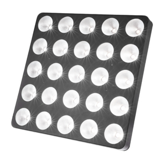
Features Features The LED blinder is particularly suitable for lighting applications in clubs and discotheques, on rock stages, and in theatres and musicals. Special features of the device: 25 warm white LEDs (3 W each), arranged in a 5×5 matrix Control via DMX (four different modes) and via buttons and display on the device 26 pre-programmed automatic shows LED matrix allows the display of letters and numbers... -
Page 14: Installation
Installation Installation Unpack and check carefully there is no transportation damage before using the unit. Keep the equipment packaging. To fully protect the product against vibration, dust and moisture during transportation or storage use the original packaging or your own packaging material suitable for transport or storage, respectively. - Page 15 Installation NOTICE! Risk of overheating and fire due to inadequate distance and bad ventilation! If the distance between the light source and the illuminated surface is too short or the device is badly ventilated, the device can overheat and cause fires. Make sure that illuminated surfaces are more than 2 m away.
- Page 16 Installation NOTICE! Data transfer errors due to improper wiring! If the DMX connections are wired incorrectly, this can cause errors during the data transfer. Do not connect the DMX input and output to audio devices, e.g. mixers or ampli‐ fiers. Use special DMX cables for the wiring instead of normal microphone cables.
-
Page 17: Starting Up
Starting up Starting up Create all connections while the device is off. Use the shortest possible high-quality cables for all connections. Take care when running the cables to prevent tripping hazards. Connections in DMX mode Connect the DMX input of the device to the DMX output of a DMX controller or another DMX device. - Page 18 Starting up Connections in master/slave When you configure a group of devices in master/slave mode, the first unit will control the mode other units for an automatic, sound-activated, synchronized show. This function is ideal when you want to start a show immediately. Connect the DMX output of the master device to the DMX input of the first slave device.
-
Page 19: Connections And Controls
Connections and controls Connections and controls ö ö DMX In DMX Out ö ö '& LED Matrix Blinder 5×5 MKII Blinder... - Page 20 Connections and controls 1 Thread holes (M10), suitable for connecting elements 2 Safety cable eyelet 3 Locking screws for the bracket 4 Bracket for suspension or set-up 5 [DMX Out] | DMX output, designed as XLR panel socket, 3-pin 6 [DMX In] | DMX input, designed as XLR panel plug, 3-pin 7 Fuse holder 8 [POWER IN] | Lockable input socket (Power Twist) for the power supply of the device 9 [POWER OUT] | Lockable output socket (Power Twist) for powering further devices...
-
Page 21: Operating
Operating Operating 7.1 Starting the device Connect the device to the power supply to start operation. After a few seconds, the display indicates that a reset is in progress. The device is then ready for use. The display shows the operating mode that was selected when the unit was last powered off. - Page 22 Operating Operating mode ‘Preprog‐ Press [Mode] repeatedly until the display shows ‘Pr.xx’ . Now you can select one of the preprog‐ rammed automatic show’ rammed automatic shows. Use [Up] and [Down] to select a value between ‘Pr.01’ and ‘Pr.26’ . To adjust the programme speed, press [Setup].
- Page 23 Operating DMX mode Press [Mode] repeatedly until the display shows ‘dxxx’ . Now you can set the number of the first DMX channel to be used by the device (DMX address). Use [Up] and [Down] to select a value between 1 and 512 (the display shows ‘d001’ … ‘d512’ ). Make sure that this number matches the configuration of your DMX controller.
- Page 24 Operating Operating mode ‘Slave’ In the master-slave configuration, you can interconnect four devices of the same type to one large matrix with 10 × 10 LEDs. The effects then use this device combination in common. Press [Mode] repeatedly until the display shows ‘SLAv’ . S.1-1 S.1-2 Press [Setup].
- Page 25 Operating Testing the LED matrix Press [Mode] repeatedly until the display shows ‘TEST’ . Now all LEDs of the matrix light up. Operating mode ‘Automatic’ Press [Mode] repeatedly until the display shows ‘AUTO’ . The playback of the random show starts automatically.
-
Page 26: Menu Overview
Operating 7.3 Menu overview 7.4 Functions in 1-channel DMX mode Channel Value Function 0…255 Dimmer (0 % to 100 %), for all LEDs together LED Matrix Blinder 5×5 MKII Blinder... -
Page 27: Functions In 4-Channel Dmx Mode
Operating 7.5 Functions in 4-channel DMX mode Channel Value Function 0…255 Dimmer (0 % to 100 %), for all LEDs together Operating mode LEDs off 1…11 Preprogrammed automatic show no. 1 12…23 Preprogrammed automatic show no. 2 240…251 Preprogrammed automatic show no. 21 252…255 Sound-controlled show 0…255... -
Page 28: Functions In 26-Channel Dmx Mode
Operating 7.6 Functions in 26-channel DMX mode The figure alongside shows the numbering of the LEDs. Channel Value Function 0…255 Dimmer (0 % to 100 %), for all LEDs together 0…255 Dimmer (0 % to 100 %), for LED no. 1 0…255 Dimmer (0 % to 100 %), for LED no. -
Page 29: Functions In 28-Channel Dmx Mode
Operating 7.7 Functions in 28-channel DMX mode The figure alongside shows the numbering of the LEDs. Channel Value Function 0…255 Dimmer (0 % to 100 %), for all LEDs together 0…255 Dimmer (0 % to 100 %), for LED no. 1 0…255 Dimmer (0 % to 100 %), for LED no. - Page 30 Operating Channel Value Function 230…239 Preprogrammed automatic show no. 21 240…255 Sound-controlled show Selection of the displayed letter (if channel 27 = 10…19) 0…9 Letter ‘A’ 10…19 Letter ‘B’ 20…29 Letter ‘C’ 30…39 Letter ‘D’ 40…49 Letter ‘E’ 50…59 Letter ‘F’ 60…69 Letter ‘G’...
- Page 31 Operating Channel Value Function 130…139 Letter ‘N’ 140…149 Letter ‘O’ 150…159 Letter ‘P’ 160…169 Letter ‘Q’ 170…179 Letter ‘R’ 180…189 Letter ‘S’ 190…199 Letter ‘T’ 200…209 Letter ‘U’ 210…219 Letter ‘V’ 220…229 Letter ‘W’ 230…239 Letter ‘X’ 240…249 Letter ‘Y’ 250…255 Letter ’Z’...
- Page 32 Operating Channel Value Function 56…83 Number ‘2’ 84…111 Number ‘3’ 112…139 Number ‘4’ 140…167 Number ‘5’ 168…195 Number ‘6’ 196…223 Number ‘7’ 224…251 Number ‘8’ 252…255 Number ‘9’ Speed adjustment (if channel 27 = 30…255) 0…255 Increasing speed LED Matrix Blinder 5×5 MKII Blinder...
-
Page 33: Temperature Monitoring
Operating 7.8 Temperature monitoring The built-in fan turns on automatically as soon as a certain temperature is reached. If a second temperature limit is exceeded despite the turned on fan, the unit automatically switches off. In this case, let the unit cool down before powering it up again. The temperature-controlled shutoff function is constantly monitored by the device. -
Page 34: Technical Specifications
Technical specifications Technical specifications Light source 25 × LED, each 3 W (warm white) 450 mm Light source properties Colour temperature 2800 K Colour rendering index 80 Ra Optical properties Beam angle approx. 55° Diameter of lenses 6.3 cm Control DMX, buttons and display on the unit Number of DMX channels 1, 4, 26 or 28... - Page 35 Technical specifications Fuse 5 mm × 20 mm, 2 A, 250 V, slow blow International Protection IP20 Rating Mounting options Hanging, standing M6 M10 threaded holes, suitable for connecting elements Dimensions (W × H × D) 450 mm × 450 mm × 115 mm Weight 10.2 kg Ambient conditions...
-
Page 36: Plug And Connection Assignments
Plug and connection assignments Plug and connection assignments Introduction This chapter will help you select the right cables and plugs to connect your valuable equip‐ ment so that a perfect light experience is guaranteed. Please take our tips, because especially in ‘Sound & Light’ caution is indicated: Even if a plug fits into a socket, the result of an incorrect connection may be a destroyed DMX controller, a short circuit or ‘just’... - Page 37 Troubleshooting Troubleshooting NOTICE! Data transfer errors due to improper wiring! If the DMX connections are wired incorrectly, this can cause errors during the data transfer. Do not connect the DMX input and output to audio devices, e.g. mixers or ampli‐ fiers.
- Page 38 Troubleshooting Symptom Remedy The device is not working, Check the mains connection and the fuse. no light No response to the 1. If the first display digit is not flashing in “DMX” mode, then DMX controller no valid DMX signal is being received. Check that the DMX controller is switched on.
- Page 39 Cleaning Cleaning Optical lenses Clean the optical lenses, that are accessible from the outside, regularly in order to optimize the light output. The frequency of cleaning depends on the operating environment: wet, smoky or particularly dirty surroundings can cause more accumulation of dirt on the optics of the device.
- Page 40 Protecting the environment Protecting the environment Disposal of the packing material Environmentally friendly materials have been chosen for the packaging. These materials can be sent for normal recycling. Ensure that plastic bags, packaging, etc. are disposed of in the proper manner. Do not dispose of these materials with your normal household waste, but make sure that they are collected for recycling.
- Page 41 Protecting the environment Disposal of your old device This product is subject to the European Waste Electrical and Electronic Equipment Directive (WEEE) as amended. Do not dispose of your old device with your normal household waste; instead, deliver it for controlled disposal by an approved waste disposal firm or through your local waste facility.
- Page 42 Notes LED Matrix Blinder 5×5 MKII Blinder...
- Page 44 Musikhaus Thomann · Hans-Thomann-Straße 1 · 96138 Burgebrach · Germany · www.thomann.de...
Need help?
Do you have a question about the LED Matrix Blinder 5x5 MKII and is the answer not in the manual?
Questions and answers