
Related Manuals for FlySky Noble NB4+


Summary of Contents for FlySky Noble NB4+
- Page 2 2. Hereby, [ShenZhen FLYSKY Technology Co., Ltd.] declares the RF equipment [Noble NB4+,NB4+] to be in accordance with RED2014/53/EU. 3. The full text of the EU DoC is available at: www.flyskytech.com/info_detail/10.
-
Page 3: Right View
Right View: Display [12] Built-in Antenna Transmitter LED [13] Speaker Transmitter Power Button [14] Neck Strap Hook [15] [16] [17] Steering Wheel [18] Base Battery Indicator [19] Detachable Base USB 5V 2A Port [10] Base Power Button [11] Type-C input port, Firmware Update, Charging Jack, Connect to Simulator Port, Trainer Interface, Head Tracker Interface... -
Page 4: Left View
Left View: [20] Steering Wheel Swivel Bracket [25] [21] [26] [22] Trigger [27] [23] [28] Battery Compartment , Built-in [24] Handle 3450mAh 18650 Battery... - Page 5 • Note: Do not completely unscrew the adjustment screws. [29] Throttle Trigger Structure Travel Adjustment Hole [30] Throttle Trigger Tension Adjustment Hole [31] Steering Wheel Tension Adjustment Hole [32] Throttle Trigger Size Adjustment Hole [37] [33] Clip [34] Handle Power Port [35] Clip Slot [36]...
- Page 6 Detachable base Removeable Transmitter Base. When active the base can power the transmitter, or other 5V external electronic devices via the USB port. When the transmitter needs to be charged or when charging the base, plug in the USB Type-C cable and charge it through the Type-C port located on the base.
- Page 7 Power On Before use make sure that the battery is fully charged. Press and hold the transmitter power button until the screen turns on. Power Off Disconnect the receiver from it's power supply. Press and hold the transmitters power button until the screen powers off.
- Page 8 LED Indicatory The Noble NB4+ has 2 status indicators, one below the screen on the top of the transmitter and one on the detachable base. Transmitter LED The LED can be set to five different colors: red, green, blue, yellow and white. You can also turn the LED off completely. Setup: Touch the function menu icon , then touch the [System];...
- Page 9 Base Battery Indicator The Base Battery Indicator has 4 LEDs and is mainly used to display bases battery level. When the base battery voltage is low, the base LED will only have one LED light on and start flashing. When charging the LED will flash and the amount of active LEDs will increase as the battery charges.
- Page 10 Failsafe This feature is designed to protect models and their users in the event of a loss of signal. The Failsafe function can be set in the three ways, you can set to no output status for i-BUS&PPM signals. You can set all channels separately to no output, hold or fixed value.
- Page 11 Servos Frequency This function is used to adjust the servo control frequency. This function can be used for analog servos (95Hz), digital servos (380Hz) and can also be set to custom. Digital servos and custom frequencies range between 50-400Hz. The servos frequency varies slightly with the connected receivers. For the Classic Version Receiver Setup: Click [Servos Frequency].
- Page 12 For the Enhanced Version Receiver [SR]: One of the specifications in the servo frequency (PWM frequency is 833 Hz). [SFR]: One of the specifications in the servo frequency (PWM frequency is 1000 Hz). Note: the conventional servo response speed (PWM frequency) is 50-400 Hz. The overall system delay will be decreased when SR and SFR are selected.
- Page 13 This firmware can be updated via the following two ways. • The firmware of this receiver can be updated through the FlyskyAssistant (The firmware of FlyskyAssistant is available on the Flysky official website). • Or update it by following the steps below: Download and open the latest official software;...
- Page 14 After completing the above steps, click [Update] in the computer update software window to start the update; Once the update is complete, the transmitter will exit the update function automatically and reboot. (It is now safe to remove the USB Type-C cable). •...
- Page 15 Setup: • Some receivers such as GMR and INr4 need to be updated with "Flysky Assistant". • If the transmitter has successfully coded and the connection is established, if the receiver firmware is the latest version, a pop-up prompt will appear [The current version is the new version, no upgrade is required! ].
- Page 16 There are two methods to let the receiver into forced update mode: 1. Power on the receiver while pressing the BIND button for more than 10 seconds, until the LED is in a state of three-time flashing and one off, then release the BIND button.
- Page 17 Connect to battery positive pole BVD harness Connect to battery negative pole Put the transmitter to enter bind mode; Press and hold the receiver BIND button while powering on the receiver, then release the BIND button after receiver is powered on, or power on the receiver first, then press and hold the BIND button 3 seconds, the LED of the receiver will flash rapidly, indicating that the receiver is in bind mode;...
- Page 18 Trigger Spring Replacement 1、Remove 4 screws(PWA 2、Remove the upper trigger 2.1*6mm); cover; 3、Adjust the screw(HB2*9mm) 4、Lift the upper end of the with a metric 1.5mm hexagonal spring, and finally the spring is screwdriver and adjust the spring removed; adjusting block to the very bottom; The upper end of the spring is Spring Adjusting Block detached first...
- Page 19 7、Install the upper trigger cover; 8、Lock 4 screws(PWA 2.1*6mm) to secure trigger cover; 9、 Complete the trigger spring replacement. Steering Wheel Spring Replacement 1、First insert a metric 2.5mm 2、 Turn a metric 2.5mm hexagonal hexagonal screwdriver into the screwdriver counterclockwise screw hole used to secure the until the screw(HM3*12mm) is steering wheel;...
- Page 20 3、Remove the steering wheel; 4、Pinch the brake pad with two fingers and take out upwardly; 5、Remove the screws by 6、Steering wheel base detached; turning them counterclockwise with a metric 1.5mm hexagonal screwdriver; 7、FPC wire detached, then remove the steering wheel base; FPC wire detached...
- Page 21 8、Remove 9、Remove the cap; screws(PWA2.1*6mm); 10、Remove the upper steering 11、Lift the spring hook with one wheel pad cover; hand and remove the steering wheel shaft with the other hand; Lift the spring hook remove the steering wheel shaft 12、Remove the spring hook 13、...
- Page 22 14、Lift the spring hook with one 15、Install the upper steering wheel hand and install the steering wheel cover; shaft with the other hand; Lift the spring hook Install the steering wheel shaft 16、Install the cap; 17、Lock the screws(PWA2.1*6mm);...
- Page 23 18、Connect the FPC wire; 19、 Lock the screws (HB2*9mm) ; 20、Install the brake pad; 21、 Use the mounting slot of the steeringwheel with brake pad adjustment hole to place over the protruding connector of the brake pad, then press the steering wheel to fix it.
- Page 24 22、Insert the screw(HM3*12) into 23、Complete the steering wheel the screw hole used to secure the spring replacement. steering wheel, then align a metric 2.5mm hexagonal screwdriver with the hexagonal hole in the head of the screw, hold the side of the steering wheel with one hand and turn the screwdriver clockwise with another hand until the screw is secured;...
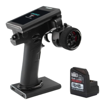
- Page 25 Specifications Product Model Noble NB4+ Compatible Receivers FGr4B and other AFHDS 3 receivers Compatible Models Car or Boat Number of Channels 2.4GHz ISM Maximum Power < 20dBm(EU) (e.i.r.p.) (EU) RF Protocol AFHDS 3 Low Voltage Alarm < 3.65V Data Connector USB Type-C Charging Jack USB Type-C...
- Page 26 用户和安装人员提供天线安装说明和发射机操作条件, 以满 足射频暴露合规要求。 特 此, 【ShenZhen FLYSKY Technology Co., Ltd.】 声 明 无 线 电 设 备 【Noble NB4+, NB4+】 符 合 RED2014/53/ 欧 盟 DoC 声 明 全 文 可 在 以 下 互 联 网 地 址: www.
- Page 27 右视图: 显示屏 [12] 内置天线 发射机 LED 灯 [13] 喇叭 发射机电源键 [14] 吊环 [15] [16] [17] 手轮 [18] 底座电量指示灯 [19] 充电底座 USB 5V 2A 输出 [10] 底座电源键 [11] Type-C 输入接口、固件更新、 充电接口、连接模拟器接口、 教练接口、头追接口...
- Page 28 左视图: [20] 手轮旋转支架 [25] [21] [26] [22] 扳机 [27] [23] [28] 电池仓,内置单节 [24] 手柄 3450mAh 18650 电池...
- Page 29 • 注意:调节时请勿将调节螺丝拧出。 [29] 扳机结构行程调节孔 [30] 扳机松紧度调节孔 [31] 手轮松紧度调节孔 [32] 扳机尺寸大小调节孔 [33] 卡扣 [34] 手柄电源连接口 [35] 卡扣槽位 [36] 底座电源连接口 [37] [37] 18650 电池盖...
- Page 30 底座 发射机底座可拆卸。 此底座在按压底座电源键后可为发射机供电,也可以通过 底座的 USB 输出端为外部电子设备供电。 当发射机需要充电时 ,通过底座 Type-C 输入端,插入 USB Type-C 线即可充电。...
- Page 31 开机 检查系统状态,确保:电池 电量充足; 长按发射机电源键,直至屏 幕亮起,表示开机。 关机 断开接收机电源; 长按发射机电源键,直至屏 幕熄灭,表示关机。 关闭前,请务必先断开接收机电源,然后关闭发射机。 如果强行关闭发射机,将有可能导致遥控设备失控或者 引擎继续工作而引发事故。...
- Page 32 LED 指示灯 Noble NB4+ 有两种 LED 指示灯,分别是发射机 LED 灯、 底座电量指示灯。 发射机 LED 灯 可自定义 LED 颜色或选择选项里已定义的颜色(红色、绿 色、蓝色、黄色或白色),也可以关闭 LED 灯显示。 功能设置: 点击主界面 ,进入功能菜单界面,选择进入 [ 系统 设置 ] 功能; 点击 [LED],进入设置界面; 根据需要选择颜色, 点击 , 显示为 表示选择成功, 同时发射机 LED 指示灯会显示对应颜色。 若选择自定义 LED 颜色,则点击 [ 自 定义...
- Page 33 底座电量指示灯 由四个 LED 灯组成,主要用于显示底座的电池电量。 当底座电量低时底座 LED 灯将会仅有一个 LED 灯亮同时闪 烁; 当底座正在充电时,LED 灯将会闪烁,同时按照实际 电量 LED 灯灯亮个数也会变化。 底座电源键操作: 按下底座电源键,底座电量指示灯亮起即给发射机充电或 USB 输出端口输出 5V 电压,可给外部设备充电。再次长 按底座电源键,底座电量指示灯灭同时停止充电。 请勿同时给发射机及外部设备充电 ,否则可能影响发 射机充电饱和时间,甚至外部设备负载过大时会触发 过载保护。...
- Page 34 失控保护 该功能用于在接收机丢失信号或失控后,保护模型和操作 人员的安全。 失控保护有三种设置方式, 可设置 i-BUS&PPM 无输出状态 ; 可对所有通道单独设置, 其中包括 [ 无输出 ]、 [ 保持 ] 和 [ 固 定值 ] 三种输出状态;可将所有已设固定值的通道设置为 当前输出值。 i-BUS&PPM 无输出 点击选项右侧 ,取消后,失控后按各通道设置:固定值 或者保持最后输出值。系统默认开启状态。 此功能开启后,不管各通道失控保护如何设置,这两类信 号失控保护始终为无输出。 设置单独通道 选择所需要的通道,进入此通道设置界面; 根据需要选择点击对应功能 , 移动对应通道的扳机、手 轮、按键、或旋钮至所需设置位置并且保持不动,点 击返回图标即设置完成。 设置所有固定值通道 点击 [ 设置所有固定值通道 ] 后,需同时将控件拨到需要的 位置并保持,在弹出的提示弹窗“设置所有失控保护为固定...
- Page 35 舵机响应速度 此功能用于调节通道输出控制舵机频率,该功能包括模拟 舵机(95Hz)、数字舵机(380Hz)、自定义,可根据 使用的舵机选择或设置正确的输出频率值,系统默认数字 舵机,自定义频率调节范围在 50-400Hz 之间。 连接不同的接收机,舵机响应速度的功能略有不同。 连接经典版接收机 功能设置: 点击进入 [ 舵机响应速度 ]; 根据需要选择点击对应功能,点 击 返回上一级界面; 若发射机高频设置选择 [AFHDS3 单向 ], 修改舵机响应速度再按退 出按钮 将弹出提示“对码或重 新对码后生效,是否对码?” 若选择 [ 自定义 ], 请点击屏幕 “+” 或“-”进行频率调节。...
- Page 36 连接增强版接收机 [SR]: 舵机响应速度中的一种规格 (PWM 频率为 833Hz)。 [SFR]: 舵机响应速度中的一种规格 (PWM 频率为 1000Hz)。 注:常规的舵机响应速度(即 PWM 的频率) 是 50-400Hz,当选用 SR、SFR 时整个系统的 延时会减小,请确保适配的舵机支持对应的频 率的,否则可能导致舵机无法正常工作,甚至 损坏舵机。 功能设置: 点击 [ 方向:数字舵机 ] 或其他选 项进入功能设置界面; 根据适配接收机的实际情况选择 点击对应舵机响应速度,点击 返回上一级界面;点击 [ 与高频 同步的勾选框,图标将会变为 ,勾选后此功能的舵机响应速度 将同步至高频 ; 若选择 [ 自定义 ], 点击 “+” 或 “-” 调节频率。...
- Page 37 模拟舵机(95Hz)、数字舵机(380Hz)为市场上 较通用舵机频率值, 故单独设定以便用户快捷操作, 为了使舵机正常运行,请先查阅舵机使用说明书确 认舵机正确频率,然后通过该功能对舵机频率数值 进行更改。 固件更新 此发射机的内置软件程序能够通过使用 USB Type-C 线与 windows 计算机连接后进行软件更新升级。一旦此功能被 激活后,发射机所有功能将停止工作。为了防止车辆失去 控制,请在进入此功能前断开接收机电源。 • 当固件正在更新时请勿断开 USB Type-C 线 警告 固件更新可通过如下两个途径完成。 • 可使用“遥控管家”进行更新(富斯遥控管家固件可 从官网 www.flyskytech.com 获取); • 或通过如下步骤更新: 下载并打开最新的官方软件; 将发射机通过 USB Type-C 线与电脑连接; 点击 [ 固件更新 ],界面弹出提示“更新固件 可能会导致模型数据恢复成出厂默认值 是否更 新?”,点击...
- Page 38 更新完成后,发射机将会自动退出更新状态,重 新开机。(断开 USB Type-C 线连接,并关闭电 脑更新软件) • 系统更新完成后可能会导致接收机无法连接 , 此 注意 时需要更新高频与接收机 更新高频 更新步骤: 更新 RF 功能可更新内置 RF 模块固件。 当发射机更新固件后,提示高频故障或对码不了接收机时, 需要更新高频。 点击 [ 更新高频 ] 更新,弹出提示界面后点击“是 " 后界面 弹出更新进度条,等待几秒后更新完成后发射机自动退出更 新界面。如发射机无法进入更新高频状态,可能是无高频模 块或高频模块故障。 更新接收机 当发射机更新程序后,为了实现功能的优化,对应的接收 机也需要更新程序。 不同的接收机进入固件更新状态的方式可能不同,请进入 官网 www.flyskytech.com 中查询相关接收机的说明书进行 操作。 更新步骤: 点击...
- Page 39 • 如果发射机已经对码成功,并且建立连接,如接收机为最 新版本, 则弹出提示 [ 当前版本已是新版本, 无需升级! ]。 若接收机为旧版本, 则弹出提示 [ 确定将接收机更新吗? ]。 弹出提示框后选择“确定”,点击 [ 升级 ] 即可将接收机 更新。 • 如果接收机与发射机未建立连接, 则进入选择接收机界面, 勾选需要连接的接收机之后弹出提示 [ 请连接 XX 或使 XX 进入强制更新模式 ], 点弹出提示框后选择 “确定” , 点击 [ 升 级 ] 进入更新状态! 可通过两种方式使接收机进入强制更新 状态:...
- Page 40 CH4(NPA) BVD/VCC LED 指示灯 对码按键 CH3(NPB) 天线 CH2(NPC) CH1(NPD) 接电池正极 BVD 功能配件 接电池负极 使发射机进入对码状态 ; 按住接收机对码按键同时上电后松开对码键(或者先 给接收机上电后,长按对码键 3 秒),接收机指示灯 快闪,表示进入对码状态; 当接收机指示灯变为常亮时,对码成功 ; • 当对码的发射机是单向模式进入对码状态时,接 收机收到对码信息后指示灯慢闪;然后手动将发 射机退出对码状态,接收机指示灯变为常亮表示 对码成功; 检查发射机、接收机、模型是否正常工作。如需重新 对码,请重复以上步骤。 此步骤适用于 Noble NB4+ 与 FGr4B 的接收机对码,如您使 用的是其他接收机,请进入官网查询对应接收机的使用说明 书进行操作。...
- Page 41 扳机弹簧更换说明 1、 取下 4 颗螺丝 (PWA 2.1*6mm) ; 2、 取下扳机上盖; 3、 用 1.5mm 六 角 扳 手 调 节 螺 丝 4、上提弹簧上端先从挂扣处脱离, (HB2*9mm), 把 弹 簧 调 节 块 调 最后取下弹簧; 到最底部; 弹簧调节块 弹簧上端先脱离 5、弹簧下端先挂上弹簧调节块,弹 6、 用 1.5mm 六 角 扳 手 调 节 螺 丝 簧上提挂上弹簧钩;...
- Page 42 7、装配上盖; 8、锁上 4 颗螺丝(PWA 2.1*6mm) 固定扳机上下盖; 9、 扳机弹簧更换完成。 手轮弹簧更换说明 1、先将 2.5mm 六角螺丝刀插入用 2、再逆时针转动 2.5mm 六角螺丝 于固定手轮的螺丝孔中; 刀直至螺丝(HM3*12mm)完全松 动后取出;...
- Page 43 3、取下手轮; 4、两指捏住原先装好的刹车片并用 力向上取出; 5、用 1.5mm 六角扳手逆时针旋转 6、手轮固定座脱离; 取下螺丝; 7、FPC 线脱离,取下手轮固定座; FPC 线脱离...
- Page 44 8、取下螺丝(PWA 2.1*6mm); 9、取下盖板; 10、取下轮盘上盖; 11、一手上提弹簧钩,一手取出手 轮轴; 弹簧钩上提 取出手轮轴 12、取下弹簧钩及弹簧组件,并且 13、 装配弹簧钩组件; 更换弹簧;...
- Page 45 14、 一手上提弹簧钩, 一手装配手轮轴; 15、装配轮盘上盖; 弹簧钩上提 装入手轮轴 16、装配盖板; 17、锁上螺丝(PWA 2.1*6mm);...
- Page 46 18、连接 FPC 线; 19、锁紧螺丝(HB2*9mm); 20、装配刹车片; 21、将带有刹车片调节孔的手轮的 安装槽套住刹车片上突出的连接头, 按压手轮使其固定;...
- Page 47 22、把螺丝(HM3*12)插入用于固 23、手轮弹簧更换完成。 定手轮的螺丝孔中,再将 2.5mm 六 角螺丝刀对齐螺丝钉头部的六角孔, 用手握住手轮侧面,另外一只手顺 时针转动螺丝刀直至螺丝固定; 扳机调节块说明 本发射机包装附件里包含三款扳机调节块。 • 标识 S 和 L 的扳机调节块不能调节扳机开口大小; • 另外的一个扳机调节块可调节扳机开口大小。 开口大小须通过扳机侧面的螺丝调节。 可根据实际情况选择合适的扳机调节块。...
- Page 48 规格参数 产品型号 Noble NB4+ 适配接收机 FGr4B 等 AFHDS 3 协议接收机 适配模型 车、船 通道个数 无线频率 2.4GHz ISM 发射功率 < 20dBm 无线协议 AFHDS 3 低电压报警 < 3.65V 数据接口 USB Type-C 充电接口 USB Type-C 天线类型 内置单天线 显示方式 3.5 英寸 320*480 全点阵彩色 IPS 触摸显示屏 通道分辨率...
- Page 49 FCC ID: 2A2UNNB4PLUS00 出版日期 :2024-07-08 Copyright ©2024 Flysky Technology Co., Ltd. Manufacturer:ShenZhen FLYSKY Technology Co., Ltd. Address: 16F, Huafeng Building, No. 6006 Shennan Road, Futian District, Shenzhen, Guangdong, China...
Need help?
Do you have a question about the Noble NB4+ and is the answer not in the manual?
Questions and answers