FlySky Noble NB4 Pro+ Quick Start Manual
Hide thumbs
Also See for Noble NB4 Pro+:
- User manual (71 pages) ,
- User manual (31 pages) ,
- User manual (32 pages)
Advertisement
Advertisement
Table of Contents

Related Manuals for FlySky Noble NB4 Pro+


Summary of Contents for FlySky Noble NB4 Pro+
- Page 2 2. Hereby, [ShenZhen FLYSKY Technology Co., Ltd.] declares the RF equipment [Noble NB4 Pro+ (NB4 Pro+), NB4 Pro+] to be in accordance with RED2014/53/EU.
- Page 3 for a Class B digital device pursuant to part 15 of the FCC rules. These limits are designed to provide reasonable protection against harmful interference in a residential installation. This equipment generates, uses and can radiate radio frequency energy and, if not installed and used in accordance with the instructions, may cause harmful interference to radio communications.
- Page 4 battery into fire or a hot oven, or mechanically crushing or cutting of a battery, that can result in an explosion; leaving a battery in an extremely high temperature surrounding environment that can result in an explosion or the leakage of flammable liquid or gas; battery subjected to extremely low air pressure that may result in an explosion or the leakage of flammable liquid or gas.
- Page 5 RF Exposure Compliance This equipment complies with FCC/ISED radiation exposure limits set forth for an uncontrolled environment. This transmitter must not be co-located or operating in conjunction with any other antenna or transmitter. These requirements set a SAR limit of 4 W/kg averaged per ten gram of tissue.
-
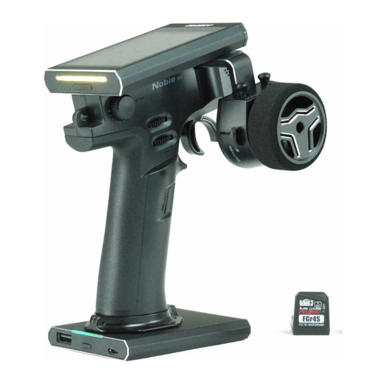
Page 6: Transmitter Overview
Transmitter Overview Cell Phone Holder Forced Shutdown Button Steering Wheel (Situated at the (Can be rotated 180° ) bottom of the grip) Base with charging function (Detachable Base) - Page 7 Holder Connection Hole Display Lanyard Eye Adjust Trigger Size Adjust Trigger Tension Grip Adjust Steering Wheel Tension Adjust Trigger Structure Travel Adjust Steering Wheel Rotate Travel 18650 Battery Cover(Detachable)
- Page 8 Steering Wheel Swivel Bracket Transmitter LED Transmitter Power Button Spring Clip Power Port Spring Clip Slot Power Port Base Battery Indicator Type-C input port, Firmware Update,Charging Jack, Connect to Simulator Port, Connect to Game Handle PortTrainer Interface, Head Tracker Interface Base Power Button USB 5V 2A Port...
-
Page 9: Charging Mode
Detachable Base The transmitter base is a removeable base. Press the power button located on the base to power it on and begin charging the transmitter via the transmitter connector or other 5V devices via the USB port. Press and hold the power button again to turn off the charging function. - Page 10 Note: Please use the USB Type-C cable shipped with this transmitter to charge it. Improper use may cause charging failure. Wireless charging • When the transmitter base indicator of the wireless charger is blue, it indicates the connection is successful and there is ongoing charging.
- Page 11 Power On To power on the transmitter. Setup: 1. Before use make sure that the battery is fully charged. 2. Press and hold the transmitter power button until the screen turns on. Power Off To power off the transmitter. Setup: 1.
-
Page 12: Led Indicator
LED Indicator The Noble NB4 Pro+ has 2 status indicators, one below the screen is on the top of the transmitter and one is located at the detachable base. Transmitter LED The LED can be set to five different colors: red, green, blue, yellow and white. - Page 13 i-BUS & PPM signal no output If the checkbox on the right of the option is not ticked ( ), it indicates that the function is disabled. After the out-of-control, you can set by channel: fixed value or keeping the last output value. After Set i-BUS-out &PPM to no output is selected, regardless of failsafe setting, these two types of failsafe signals are always no output.
-
Page 14: Servos Frequency
Servos Frequency This function is used to adjust the servo control frequency. This function can be used for analog servos (95Hz), digital servos (380Hz) and can also be set to custom. Digital servos and custom frequencies range between 50-400Hz. The servos frequency varies slightly with the connected receivers. For the Classic Version Receiver Setup: 1. - Page 15 Note: the conventional servo response speed (PWM frequency) is 50-400 Hz. The overall system delay will be decreased when SR and SFR are selected. Make sure that the adapted servo supports the corresponding frequency. Otherwise, it may cause the servo not to work properly or even damage the servo.
-
Page 16: Firmware Update
This firmware can be updated via the following two ways. • The firmware of this receiver can be updated through the Flysky Assistant (The firmware of Flysky Assistant is available on the Flysky official website). • Or update it by following the steps below: 1. - Page 17 Setup: • Some receivers such as GMr needs to be updated with "Flysky Assistant". • If the transmitter has successfully coded and the connection is...
- Page 18 • If the receiver and the transmitter are not connected, then enter the receiver selection interface (FGr8B/FGr4B needs to be placed upright when in use), check the receiver to be connected and pop up a prompt [Please connect XX or enable XX enter the mandatory update mode] Click [OK]! After starting the update, the transmitter will display as below.
- Page 19 BIND Button FGr4B Note: Different receivers may have different ways of entering the firmware update status. Please refer to the instructions of related receivers in the website. Binding The transmitter and receiver have already been pre bound at the factory, however if you wish to bind again or bind a new receiver follow the steps below: NPA/8 VCC/BVD...
- Page 20 CH4(NPA) BVD/VCC BIND Button CH3(NPB) Antenna CH2(NPC) CH1(NPD) FGr4B 1. Put the transmitter to enter bind mode; 2. Press and hold the receiver BIND button while powering on the receiver, then release the BIND button after receiver is powered on, (or power on the receiver first, then press and hold the BIND button 3 seconds) , the LED of the receiver will flash rapidly, indicating that the receiver is in bind mode;...
- Page 21 Notes: 1. Flysky AFHDS 3 classic version receiver models: FTr10/FGr4/ FGr4s/FGr4p/FTr4/FTr16S. Other Flysky AFHDS 3 receivers are enhanced version receivers. 2. If you want to use the dual receiver mode, click the check box on the right side of [Two Rx Mode]. The icon will change and then the transmitter will enter dual receiver mode.
- Page 22 Trigger Spring Replacement 1、Remove 4 screws(PWA 2、Remove the upper trigger 2.1*6mm); cover; 3、Adjust the screw(HB2*9mm) 4、Lift the upper end of the with a metric 1.5mm hexagonal spring, and finally the spring is screwdriver and adjust the spring removed; adjusting block to the very bottom; The upper end of the spring is Spring Adjusting Block detached first...
- Page 23 7、Install the upper trigger cover; 8、Lock 4 screws(PWA 2.1*6mm) to secure trigger cover; 9、 Complete the trigger spring replacement. Steering Wheel Spring Replacement 1、First insert a metric 2.5mm 2、 Turn a metric 2.5mm hexagonal hexagonal screwdriver into the screwdriver counterclockwise screw hole used to secure the until the screw(HM3*12mm) is steering wheel;...
- Page 24 3、Remove the steering wheel; 4、Pinch the brake pad with two fingers and take out upwardly; 5、Remove the screws by turning them counterclockwise 6、Steering wheel base detached; with a metric 1.5mm hexagonal screwdriver; 7、FPC wire detached, then remove the steering wheel base; FPC wire detached...
- Page 25 8、Remove 9、Remove the cap; screws(PWA2.1*6mm); 10、Remove the upper steering 11、Lift the spring hook with one wheel pad cover; hand and remove the steering wheel shaft with the other hand; Lift the spring hook remove the steering wheel shaft 12、Remove the spring hook 13、...
- Page 26 14、Lift the spring hook with one 15、Install the upper steering wheel hand and install the steering wheel cover; shaft with the other hand; Lift the spring hook Install the steering wheel shaft 16、Install the cap; 17、Lock the screws(PWA2.1*6mm);...
- Page 27 18、Connect the FPC wire; 19、 Lock the screws (HB2*9mm) ; 20、Install the brake pad; 21、 Use the mounting slot of the steeringwheel with brake pad adjustment hole to place over the protruding connector of the brake pad, then press the steering wheel to fix it.
- Page 28 22、Insert the screw(HM3*12) into 23、Complete the steering wheel the screw hole used to secure the spring replacement. steering wheel, then align a metric 2.5mm hexagonal screwdriver with the hexagonal hole in the head of the screw, hold the side of the steering wheel with one hand and turn the screwdriver clockwise with another hand until the screw is secured;...
- Page 29 Specifications Product Model Noble NB4 Pro+ Compatible FGr8B, FGr4B and other AFHDS 3 receivers Receivers Compatible Models Car, Boat, Robot or Ironclad Number of Channels 2(Extreme-speed), 4, 6, 8, 10, 12 or 18 channels 2402.6-2479.4MHz Maximum Power 17.84dBm (for EU) RF Protocol AFHDS 3 Low Voltage Alarm...
- Page 30 开始使用前请务必在 Flysky 官网下载并阅读 《免责声明 & 警告》 了解 安全注意事项, 并在 Flysky 官网下载阅读使用说明书。 Flysky 官网地址: www.flyskytech.com 1. 此发射机所用天线的安装必须与所有人员保持一定距离, 并且不得 与任何其他发射机一起使用或使用。 必须向最终用户和安装人员提供天 线安装说明和发射机操作条件, 以满足射频暴露合规要求。 2. 特此, 【 ShenZhen FLYSKY Technology Co., Ltd.】 声明无线电设备 【Noble NB4 Pro+(NB4 Pro+), NB4 Pro+】 符合 RED2014/53/EU. 3. 欧盟 DoC 声明全文可在以下互联网地址: www.flyskytech.com/ info_detail/10.html 获取。...
- Page 31 发射机概览 手机旋转支架 强制关机按键 手轮 (置于手胶底部) (可旋转 180°) 充电底座 ( 可拆卸 )
- Page 32 支架连接孔 显示器 吊环 调节扳机尺寸大小 调节扳机松紧度 手胶 调节手轮松紧度 调节整个扳机结构的行程 调节手轮转动行程 18650 电池盖 ( 可拆卸 )
- Page 33 手轮旋转支架 发射机 LED 灯 发射机电源键 弹簧卡扣 电源连接口 弹簧卡扣槽 电源连接口 底座电量指示灯 Type-C 输入接口、固件更 新、充电接口、连接模拟器 接口、连接游戏手柄接口、 教练接口、头追接口 底座电源键 USB 5V 2A 输出...
- Page 34 发射机底座 发射机底座可拆卸。 按下底座电源键,底座电量指示灯亮起,即给发射机充电或 USB 输 出端口输出 5V 电压,可给外部设备充电。再次长按底座电源键,底 座电量指示灯灭,同时停止充电。 当发射机需要充电时 ,通过底座 Type-C 输入端,连接 USB Type-C 线即可充电。 请勿同时给发射机及外部设备充电,否则可能影响发射机充电 饱和时间,甚至外部设备负载过大时,会触发过载保护。 充电 Noble NB4 Pro+ 发射机有两种充电方式 : USB Type-C 线插入充电口 充电或使用无线充电底座对其进行充电。 电量充满后底座 4 颗灯常亮。 发射机充满电量时间约 4 小时。 注:请使用本款发射机标配的 USB Type-C 线对其进行充电,使用不 当则可能导致充电失败。...
- Page 35 无线充电 • 无线充发射端底座指示灯呈蓝色表示连接成功正在充电。 • 无线充发射端底座指示灯呈红色表示未连接发射机底座或连接不规 范。 无线充发射端底座指示灯呈蓝色常亮表示电量已经充满。整机(含发 射机和发射机底座以及无线充发射端底座)充满电量时间约 9.5 小时。 如果无线充发射端底座使用不规范会导致充电无效,甚至有损 充电效率。 发射机底座未与无线充底盘对齐或放置倾斜都属于不规范操作。...
- Page 36 开机 开启 Noble NB4 Pro+ 发射机。 功能设置: 1. 检查系统状态,确保电池电量充 足; 2. 长按发射机电源键,直至屏幕亮 起,表示开机。 关机 关闭 Noble NB4 Pro+ 发射机。 功能设置: 1. 断开接收机电源; 2. 长按发射机电源键,直至屏幕熄 灭,表示关机。 关闭前,请务必先断开接收机电源,然后关闭发射机。如果强行 关闭发射机,将会导致遥控设备失控。失控保护设置不合理可能 引起事故。...
- Page 37 LED 指示灯 Noble NB4 Pro+ 有两种 LED 指示灯,分别是发射机 LED 灯、底座电 量指示灯。 发射机 LED 灯 可自定义 LED 颜色或选择选项里已定义的颜色(红色、绿色、蓝色、 黄色或白色),也可以关闭 LED 灯显示。 功能设置: 1. 点击进入主界面 ,进入功能菜单界面,选择进入 [ 系统设置 ]; 2. 点击 [LED],进入设置界面; 3. 根据需要选择颜色,点击 ,显示 表示选择成功,同时发射机 LED 指示灯会显示对应颜色。 4. 设若选择自定义 LED 颜色,则点击 [ 自定义 ],进入设置界面,点 选要设置的选项,点击“+”或“-”设置合适的数值,也可直接触...
- Page 38 失控保护 失控保护功能用于在接收机失去信号不受控制后,接收机按预设方 式进行输出,保护模型及人员安全。 在失控保护菜单下可设置针对 i-BUS&PPM 信号无输出状态;可对 所有通道单独设置:无输出、保持或固定值;可将所有已设固定值 的通道设为当前输出值。 i-BUS&PPM 无输出 点击选项右侧 ,取消后,当模型丢失信号后对应的 i-BUS/PPM 信 号无输出。系统默认开启状态。 此功能开启后,不管各通道失控保护如何设置,这两类信号失控保 护始终为无输出。 设置单独通道 分别设置通道输出信号状态:[ 无输出 ] 表示无信号输出;[ 保持 ] 表示 失控时保持输出最后信号;[ 固定值 ] 可以通过移动控件来设置失控保 护输出值。 功能设置: 1. 选择所需要的通道,进入此通道设置界面; 2. 根据需要选择点击对应功能 , 移动对应通道的扳机、手轮、按键、 或旋钮至所需设置位置并且保持不动,点击返回图标即设置完成。 设置所有固定值通道 用于设置所有已经设置为固定值的通道失控后的输出值。 功能设置:...
- Page 39 舵机响应速度 此功能用于调节通道输出控制舵机频率,该功能包括模拟舵机 (95Hz)、数字舵机(380Hz)、自定义,可根据使用的舵机选择 或设置正确的输出频率值,系统默认数字舵机,自定义频率调节范围 在 50-400Hz 之间。 连接不同的接收机,舵机响应速度的功能略有不同。 连接经典版接收机 功能设置: 1. 点击进入 [ 舵机响应速度 ]; 2. 根据需要选择点击对应功能项,点击 返回上一级界面; • 若发射机高频设置选择 [AFHDS 3 单向 ], 修改舵机响应速度 , 点击 将弹出提示“对码或重新对码后生 效,是否对码?” 3. 若选择 [ 自定义 ],点击“+”或“-” 调节频率。...
- Page 40 连接增强版接收机 [SR]:舵机响应速度中的一种规格(PWM 频率为 833HZ)。 [SFR]:舵机响应速度中的一种规格(PWM 频率为 1000HZ)。 [ 与高频同步 ]:PWM 输出与(RF)无线 信号接收的时序同步。 注:常规的舵机响应速度 (即 PWM 的频率) 是 50-400Hz,当选用 SR、SFR 时整个系 统的延时会减小,请确保适配的舵机支持 对应的频率,否则可能导致舵机无法正常 工作,甚至损坏舵机。 功能设置: 1. 点击 [ 方向:数字舵机 ] 或其他选项进 入功能设置界面; 2. 根据适配接收机的实际情况点击相应 的舵机响应速度,点击 返回上一级 界面; • 点击 [ 与高频同步 ] 右侧的勾选框, 图标将会变为...
- Page 41 固件更新 此发射机的内置软件程序能够通过使用 USB Type-C 线与 windows 计算机连接后进行软件更新升级。一旦此功能被激活后,发射机所 有功能将停止工作。为了防止车辆失去控制,请在进入此功能前断 开接收机电源。 • 请使用随机赠送的 USB Type-C 线 警告 • 当固件正在更新时请勿断开 USB Type-C 线 固件更新可通过如下两个途径完成。 • 可使用“遥控管家”进行更新(富斯遥控管家固件可从官网 www. flyskytech.com 获取); • 或通过如下步骤更新: 1. 下载并打开最新的固件更新程序; 2. 将发射机通过 USB Type-C 线与电脑连接; 3. 点击 [ 固件更新 ],界面弹出提示“更新固件可能会导致模型数 据恢复成出厂默认值...
- Page 42 更新高频 更新 RF 功能可更新内置 RF 模块。 当遥控器更新固件后,提示高频故障或对码不了接收机时,需要更新 高频。 点击 [ 更新高频 ] 更新,弹出提示界面后点击“是 " 后界面弹出更新进 度条,等待几秒后更新完成后发射机自动退出更新界面。 注:如发射机无法进入更新高频状态,可能是无高频模块或高频模 块故障。 更新接收机 当发射机更新程序后,如无法与接收机对码,对应的接收机也需要更 新程序。 功能设置: 点击 [ 更新接收机 ]: • GMr 等一部分接收机需使用“遥控管家”进行更新。 • 如果发射机已经对码成功,并且建立连接,如接收机为最新版本, 则弹出提示 [ 当前版本已是新版本,无需升级! ]。若接收机为旧 版本, 则弹出提示 [ 确定将接收机更新吗? ]。 弹出提示框后选择 “确 定”,点击...
- Page 43 进入更新后,显示如图画面,进度 100% 时,更新成功。 注:更新接收机前,建议先更新发射机。 可通过两种方式使接收机进入强制更新状态: • 按下对码键,上电 10 秒后指示灯三闪一灭,松开对码键; • 先给接收机上电, 长按对码键 10 秒后指示灯三闪一灭, 松开对码键。 对码按键 FGr8B 对码按键 FGr4B 注:不同接收机进入强制更新状态方式不同,请参考具体接收机的说 明书。...
- Page 44 对码 本发射机和接收机在出厂前已对码成功。如果您需要重新对码时, 请按照如下步骤进行对码: LED 指示灯 NPA/8 VCC/BVD NPC/6 NPD/5 天线 对码按键 NPB/7 FGr8B 接收机概览图 CH4(NPA) BVD/VCC LED 指示灯 对码按键 CH3(NPB) 天线 CH2(NPC) CH1(NPD) FGr4B 接收机概览图...
- Page 45 1. 使发射机进入对码状态 ; 2. 按住接收机对码按键同时上电后松开对码键(或者先给接收机上电 后,长按对码键 3 秒),接收机指示灯快闪,表示进入对码状态; 3. 当接收机指示灯变为常亮时,对码成功 ; • 当对码的发射机是单向模式进入对码状态时,接收机收到对码 信息后指示灯慢闪;然后手动将发射机退出对码状态,接收机 指示灯变为常亮表示对码成功; 4. 检查发射机、接收机、模型是否正常工作。如需重新对码,请重复 以上步骤。 • 此步骤适用于 Noble NB4 Pro+ 与 FGr4B 及 FGr8B 的接收机对码, 如您使用的是其他接收机,请进入官网查询对应接收机的使用说明 书进行操作。 注: 1. 富斯 AFHDS 3 经典版接收机型号:FTr10/FGr4/FGr4S/FGr4P/ FTr4/FTr16S; 其他富斯 AFHDS 3 接收机均为增强版接收机。 2.
- Page 46 扳机弹簧更换说明 1、 取下 4 颗螺丝 (PWA 2.1*6mm) ; 2、 取下扳机上盖; 3、 用 1.5mm 六 角 扳 手 调 节 螺 丝 4、上提弹簧上端先从挂扣处脱离, (HB2*9mm), 把 弹 簧 调 节 块 调 最后取下弹簧; 到最底部; 弹簧调节块 弹簧上端先脱离 5、弹簧下端先挂上弹簧调节块,弹 6、 用 1.5mm 六 角 扳 手 调 节 螺 丝 簧上提挂上弹簧钩;...
- Page 47 7、装配上盖; 8、锁上 4 颗螺丝(PWA 2.1*6mm) 固定扳机上下盖; 9、 扳机弹簧更换完成。 手轮弹簧更换说明 1、先将 2.5mm 六角螺丝刀插入用 2、再逆时针转动 2.5mm 六角螺丝 于固定手轮的螺丝孔中; 刀直至螺丝(HM3*12mm)完全松 动后取出;...
- Page 48 3、取下手轮; 4、两指捏住原先装好的刹车片并用 力向上取出; 5、用 1.5mm 六角扳手逆时针旋转 6、手轮固定座脱离; 取下螺丝; 7、FPC 线脱离,取下手轮固定座; FPC 线脱离...
- Page 49 8、取下螺丝(PWA 2.1*6mm); 9、取下盖板; 10、取下轮盘上盖; 11、一手上提弹簧钩,一手取出手 轮轴; 弹簧钩上提 取出手轮轴 12、取下弹簧钩及弹簧组件,并且 13、 装配弹簧钩组件; 更换弹簧;...
- Page 50 14、 一手上提弹簧钩, 一手装配手轮轴; 15、装配轮盘上盖; 弹簧钩上提 装入手轮轴 16、装配盖板; 17、锁上螺丝(PWA 2.1*6mm);...
- Page 51 18、连接 FPC 线; 19、锁紧螺丝(HB2*9mm); 20、装配刹车片; 21、将带有刹车片调节孔的手轮的 安装槽套住刹车片上突出的连接头, 按压手轮使其固定;...
- Page 52 22、把螺丝(HM3*12)插入用于固 23、手轮弹簧更换完成。 定手轮的螺丝孔中,再将 2.5mm 六 角螺丝刀对齐螺丝钉头部的六角孔, 用手握住手轮侧面,另外一只手顺 时针转动螺丝刀直至螺丝固定;...
- Page 53 规格参数 产品型号 Noble NB4 Pro+ 适配接收机 FGr8B,FGr4B 等 AFHDS 3 协议接收机 适配模型 车、船、机器人、铁甲 通道个数 2 ( 极速) 、 4 、 6、 8、 10、 12、 18 可选 无线频率 2402.6-2479.4MHz 发射功率 17.84dBm (for EU) 无线协议 AFHDS 3 低电压报警 < 3.65V 数据输出 USB Type-C 充电接口...
- Page 54 FCC ID: 2A2UNNB4PRO00 IC: 25584-NB4PRO00 出版日期 : 2024-07-09 Copyright ©2024 Flysky Technology Co., Ltd. Manufacturer: ShenZhen FLYSKY Technology Co., Ltd. Address: 16F, Huafeng Building, No. 6006 Shennan Road, Futian District, Shenzhen, Guangdong, China...
Need help?
Do you have a question about the Noble NB4 Pro+ and is the answer not in the manual?
Questions and answers