FlySky Noble NB4 User Manual
Hide thumbs
Also See for Noble NB4:
- User manual (71 pages) ,
- Quick start manual (54 pages) ,
- User manual (32 pages)
Table of Contents
Advertisement
Quick Links
Advertisement
Table of Contents

Related Manuals for FlySky Noble NB4


Summary of Contents for FlySky Noble NB4
- Page 1 USER MANUAL Copyright ©2018 Flysky Technology co., ltd...
- Page 2 In order to ensure your safety, and the safety of others, read this manual carefully before using this product. If you encounter any problem during use, refer to this manual first. If the problems persists, contact your local dealer or visit our service and support website: www.flysky-cn.com...
-
Page 3: Table Of Contents
1. Safety..........................1 1.1 Safety Symbols ..................................1 1.2 Safety Guide .....................................1 2. Introduction........................2 2.1 System Features ..................................2 2.2 Transmitter Overview ................................3 2.3 Receiver Overview ..................................6 2.3.1 Status Indicator ....................................6 3 Getting Started........................6 3.1 Transmitter Battery Installation ............................7 4. Operation Instructions.....................8 4.1 Power On ....................................8 4.2 Binding .......................................8 4.3 Transmitter LED Indicator..............................8 4.4 Power Off ....................................8... - Page 4 8.4 Vibration ....................................20 8.5 LED Light....................................21 8.6 Language ....................................21 8.7 Auto Power Off ..................................21 8.8 Radio Frequency Setup...............................21 8.9 Stick Calibration..................................21 8.10 Firmware Update................................22 8.11 Factory Reset..................................23 8.12 About Noble..................................23 9. Product Specifications....................23 10. Package Contents......................24 11.Certification........................25 11.1 DoC Declaration .................................25 CE Warning .....................................25 11.2 11.3 Enviromentally Friendly Disposal..........................25...
-
Page 5: Safety
Safety 1.1 Safety Symbols Pay close attention to the following symbols and their meanings. Failure to follow these warnings could cause damage, injury or death. Danger • Not following these instructions may lead to serious injuries or death. Warning • Not following these instructions may lead to major injuries. Attention • Not following these instructions may lead to minor injuries. 1.2 Safety Guide Prohibited Mandatory • Do not use the product at night or in bad weather like rain or thunderstorm. It can cause erratic operation or loss of control. • Do not use the product when visibility is limited. •... -
Page 6: Introduction
Introduction This product uses the 2.4GHz Third Generation AFHDS 3 protocol. The NB4 and FGr4 constatute a 4 channel system, compatible with model cars, boats and other models. System Features 2.1 AFHDS3 (third-generation automatic frequency hopping digital system) is a newly developed digital wireless system. It is compatible with single antenna bidirectional real-time data packet transmission and data stream transmission. -
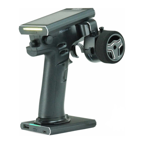
Page 7: Transmitter Overview
2.2 Transmitter Overview Speaker Lanyard Eye Battery... - Page 8 Speaker Lanyard Eye Grip Trigger spring adjsustment Trigger size adjustment Battery Port USB Port (Charging) Power Button USB Port (Power Out)
- Page 9 Adjustable Screen TH Trim RGB LED ST Trim Power Button Wheel Trigger Position Adjustment Screw Wheel Tension Adjustment Screw...
-
Page 10: Receiver Overview
2.3 Receiver Overview BIND SERVO SENS Status Indicator Antenna 2.3.1 Status Indicator The status indicator is used to indicate the power and working status of the receiver. • Off: The power is not connected. • Lit in red: The receiver is on and working. •... -
Page 11: Getting Started
Getting Started Before operation, install the battery and connect the system as instructed below. 3.1 Transmitter Battery Installation Danger • Only use included batteries Danger • Do not open, disassemble, or attempt to repair the battery. Danger • Do not crush/puncture the battery, or short the external contacts. Danger • Do not expose to excessive heat or liquids. Danger • Do not drop the battery or expose to strong shocks or vibrations. Danger • Always store the battery in a cool, dry place. Danger • Do not use the battery if damaged. The NB4 has 2 batteries, one located in the handle and one in the removeable base. To attach the base: 1. -
Page 12: Operation Instructions
Operation Instructions After setting up, follow the instructions below to operate the system. 4.1 Power On Follow the steps below to turn on the transmitter: Make sure that: • The battery is fully charged and installed correctly. • The receiver is installed correctly and powered down. Hold the power button until the screen turns on. -
Page 13: System Interface
System Interface The main interface mainly displays information related to the model, such as transmitter voltage information, function status and so on. Model Name To be added Sensors Function Status Bar Steering Channel Throttle Channel Channel 3 Channel 4 Steering Trim Trigger Trim Hold the lock icon for 2 seconds to lock or unlock the... -
Page 14: Function Settings
6. Function Settings This section details functions and their use. 6.1 Reverse The Reverse function is used to correct a servo or motor's direction in relation to the systems controls. For example, if a steering servo is mounted upside down in order to fit inside a model, when the system's steering wheel is turned, the servo will move in the opposite direction. -
Page 15: Steering Exponential
6.4 Steering Exponential This function changes the steering channel's response curve. There are 2 main parameters: • Rate: Changes the outer limits of the steering, the default and maximum is 100%. • Exp. (Exponential): Changes the steering curve, which changes the response of the steering wheel. -
Page 16: Throttle Neutral
6.7 Throttle Neutral Throttle Neutral creates a configurable dead zone for the throttle channel. Forward: How far the dead zone extends into the throttle zone. Dead Zone: The point at which the channel will kick in when the trigger passes the threshold. Backward: How far the dead zone extends into the braking zone. -
Page 17: A.b.s
6.10 A.B.S. A.B.S. stands for auto breaking system. This function is used to stop the wheels from locking which can lead to loss of control or a skid. A.B.S. manages this by regulating the amount of pressure the breaks use, which is done by pumping the breaks on and off rather than a constant force. -
Page 18: Throttle Speed
Duty Cycle Changes the length of each pulse and the gap between them. As the value changes, the length of the braking waves peaks and troughs will change independently of each other and will no longer be symmetrical. Steering Mix A.B.S. can be reduced automatically while turning. This function mixes braking and steering to turn reduce the A.B.S. -
Page 19: Throttle Idle Up
6.13 Throttle Idle Up Throttle Idle Up is used for models that use a fuel based engine that will stall if left at 0 throttle. Idle up makes sure that the engine always has some throttle in order to keep it from stalling. This function must be assigned to a switch/button in order to be activated (See [Buttons Assign]). -
Page 20: Boat Mode
6.15 Boat Mode This function is used only when you are using a model boat. When this function is active, the throttle channel is set to its lowest position and the brake functionality is disabled. To toggle this function, select the box beside [Normal mode]. When the function is active, the text beside the box will change to [Boat mode]. -
Page 21: Display Servos
6.18 Display Servos This function displays the model's channel output and can be used to test output and servo range. Press the icon to start servo test mode, which will move all the channels slowly though their entire range of motion. Press the icon to turn off servo test mode. -
Page 22: Models
6.21 Models This function is used to change, reset, rename or copy model setups. The NB4 can store up to 20 different models in the internal memory. Selecting a model: To select a model touch "Select Model", then touch a model from the list. -
Page 23: Rx Setup
7 RX Setup 7.1 Bind With A Receiver To bind with a reciever: 1. Put the receiver into bind mode (Check the receiver's user manual for your receiver on how to enter bind mode). 2. Touch "Bind With A Receiver" in the RX Setup menu. The NB4 will now bind with the receiver and exit automatically when binding is complete. -
Page 24: System
8 System 8.1 Backlight Timeout The backlight timeout function controls how long the system will wait before turning off screens backlight. Setup: 1. Select a time from the list. 8.2 Backlight This function controls the backlight brightness. Setup: 1. Use the + and - icons to change the backlight percentage. 2. -
Page 25: Led Light
8.5 LED LED Light changes the color of the LED strip located above the power button. Changing Color: 1. Touch LED Light to enter the menu. 2. Select a color from the list. 3. Touch the icon to return to the previous menu. 8.6 Language Language changes the language for the user interface. -
Page 26: Firmware Update
8.10 Firmware Update The internal software of the transmitter can be updated using the USB interface connected via a windows computer. Once this function is activated, all functions of the transmitter stop. To avoid any loss of control of the vehicle, turn its receiver off before entering this mode. -
Page 27: Product Specifications
9. Product Specifications This section contains NB4 transmitter and FGr4 receiver specifications. 9.1 Transmitter specification (NB4) Model Type Car, Boat Channels RF Range 2.402-2.480GHz RF Power <20dBm (EU) 2.4GHz Protocol AFHDS 3 Data Output Micro USB Charging Port Micro USB Antenna Type Built-in Single Antenna Input Power 1S/4.2V Lithium Polymer Battery HVGA 3.5 inch TFT color screen with a resolution of 320*480,... -
Page 28: Package Contents
10. Package Contents NB4 Transmitter FGr4 Quick Start Quide USB Wire Hand Grip L Bluetooth module x 1 (optional) Ibus Module x 1 (optional) -
Page 29: Certification
11. Certification 11.1 DoC Declaration Hereby, [Flysky Technology co., ltd] declares that the Radio Equipment [FG4] is in compliance with RED 2014/53/EU. The full text of the EU DoC is available at the following internet address: www.flysky-cn.com 11.2 CE Warning The antenna(s) used for this transmitter must be installed to provide a separation distance of at least 20 cm from all persons and must not be co-located or operating in conjunction with any other transmitter. -
Page 30: Appendix 1 Fcc Statement
Appendix 1 FCC Statement 11.4 This equipment has been tested and found to comply with the limits for a Class B digital device pursuant to part 15 of the FCC rules. These limits are designed to provide reasonable protection against harmful interference in a residential installation. - Page 31 Copyright ©2018 Flysky Technology co., ltd Release date: 2018-09-20 FCC ID: N4ZFG400...
Need help?
Do you have a question about the Noble NB4 and is the answer not in the manual?
Questions and answers