Advertisement
Table of Contents
- 1 Table of Contents
- 2 Safety Considerations
- 3 Wired Controller Features and Functions
- 4 Wired Controller Display
- 5 Wired Controller Functions
- 6 Initial Setup
- 7 Weekly Timer Operation
- 8 Week and Day Settings for Week 2
- 9 Wired Controller Error Codes
- 10 Queries and Settings
- 11 Technical Indication and Requirement
- Download this manual
Wired Remote Controller
7 Day Programmable Thermostat
Ductless Systems
KSACN0601AAA (High Wall/Console Models)
KSACN0701AAA Cassette/Ducted/Console / Air Handler Models)
Owner's Manual
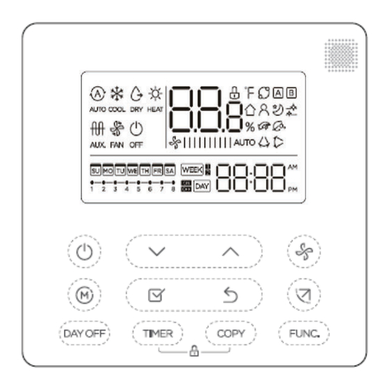
Fig. 1 — Wired Controller
NOTE: Images are for illustration purposes only. Actual models may differ slightly.
Specifications subject to change without notice.
OM-KSACN06(7)01-02
Advertisement
Table of Contents


Need help?
Do you have a question about the KSACN0601AAA and is the answer not in the manual?
Questions and answers
My unit is displaying a P4 error code and does not appear to be functioning