
Related Manuals for Regada MTR VARIANT 52 420


Summary of Contents for Regada MTR VARIANT 52 420
- Page 1 INSTALLATION, SERVICE AND MAINTENANCE INSTRUCTIONS Electric linear thrust actuators MTR VARIANT 52 420 ® 74 0716 02 74 0716 02...
- Page 2 TEST CERTIFICATE ELECTRIC LINEAR THRUST ACTUATOR MTR VARIANT 52 420 Type number ........Power supply ......V ..Hz Serial number ........Rated thrust ..........N Production year ........Switching-off thrust ........N Wiring diagram ........Rated operation speed .......mm/min ............Stroke ............mm Warranty period .....
-
Page 3: Table Of Contents
Please read these instructuctions carefully before mounting and operating the actuator. Contents 1. Description............................2 1.1 Purpose and Operation ......................2 1.2 Safety instructions........................2 1.3 Instructions for stuff training....................... 2 1.4 Data specified on electric actuator ..................... 3 1.5 Warranty conditions ........................3 1.6 Under-guarantee and after-guarantee service ................ -
Page 4: Description
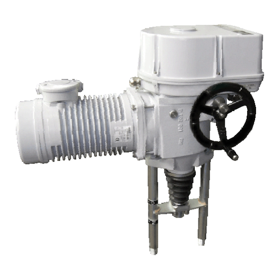
MTR 52 420 1. Description 1.1 Purpose and Operation Electric linear actuators (hereinafter EA) of MTR 52 420 (hereinafter MTR) types are high-powered electric-mechanical products designed for direct installations onto controlled devices (regulating bodies - valves, etc.). EA of MTR types are provided for remote control of closing bodies, and EA of MTR types for automotive control of regulating bodies in both directions of their movement. -
Page 5: Data Specified On Electric Actuator
MTR 52 420 Warning for safety use 1. Products are assigned for operation in environment consist of gas, steam and vapours, with temperature range: –25°C to +55°C, with pressure range from 0.8 to 1.1 bar. 2. If the actuator is placed on device which regulate medium with higher temperature than +55°C, protect the actuator by additional construction in order to maintain ambient temperature max. -
Page 6: Under-Guarantee And After-Guarantee Service
MTR 52 420 1.6 Under-guarantee and after-guarantee service Our customers are provided with professional service of our firm in installation, operation, service, maintenance, revision and help in troubleshooting for all our products. Trained professionals wait for you also in our contracted service centres. Under-guarantee service is performed by the service department of the production plant, or by a contracted service centre according to a written claim. -
Page 7: Power Supply And Duty Cycle
MTR 52 420 • with mild dustiness – with potential influence of fireproof, non-conducting and explosion-proof dust; mean dust layer; dust fall above 35, but not more than 350 mg/m per day (IP 5x) ....AE 5* • with strong dustiness – with a possibility of influences of inflammable, non-conducted and non- explosive dust;... - Page 8 MTR 52 420...
- Page 9 MTR 52 420 Module М1 – an electric motor Special capacitor asynchronous electric motor with a electrically controlled friction brake. It is suitable for continuous control with possible operation as a permanent squirrel-cage motor. Module M11 – countershaft transmission with rotary hold Countershaft transmission performs reduction of revolutions of electric - motor to specified transmission value.
- Page 10 MTR 52 420 Module М4 – a control box It is located in the upper of actuator. On the base plate (46) the following functional block are mounted: • a torque switch unit (20) • a transmission unit (10) • space heater (16) •...
- Page 11 MTR 52 420 Torque switch unit (Fig. 7) consists of the following parts: Switch element (9) (Fig.3) is formed by two micro-switches S1 and S2. It is put into operation after loosening of the nut (17). Cam unit is formed by two adjustable cams (19) and (20) (Fig.6) placed on the shaft of the torque control element (45) (Fig.2).
- Page 12 MTR 52 420 Module М8 – a linear mechanism (Fig.8) It changes rotary movement of the output shaft (3)(Fig.2) to linear movement of output spindle (83). The bronze joint nut with a trapezoidal thread is put into teeth of the output shaft (3). The frame (85) limits rotation of the output shaft (83) and function to indicate position.
-
Page 13: Technical Data Of Actuator
MTR 52 420 1.9 Technical data of actuator The basic technical data of actuator are given in the Table 1. Table No. 1 Electric motor Rated Switching-off Type/ operating Operat. 5)6) type thrust speed stroke ±15 [%] Voltage. Power output Speed Current number... -
Page 14: Mechanical Connection
MTR 52 420 Adjustment of limit positions: Position switch S3 or S4 is adjusted to specified stroke. Limit position switches are adjusted with accuracy ± 0,5 mm referring to lower position and stroke. Set up of strokes and positioning switches Initial position set up (i.e. -
Page 15: Assessment Of The Product And Packaging And Removal Of Contamination
MTR 52 420 self-motion; if open transportation means are used, to secure their protection against atmospheric precipitations and splashing water. Displacement and securing of products in transportation means must provide their stable position, exclude the possibility of their inter-collision and their collision with the vehicle walls. -
Page 16: Installation And Dismantling Of Actuator
MTR 52 420 2. Installation and dismantling of actuator 2.1 Installation Abide by safety measures! Before starting of mounting the EA onto the valve: • Check again whether the EA was not damaged during storing. • Check whether the adjusted operation angle and connecting dimensions of the actuator (see the nameplate) are in compliance with the valve parameters. - Page 17 MTR 52 420 a) Terminal board connection Connecting of the motor. Electric connection should be made through 2 cable glands M25 x 1,5. The recommended diameter of the connecting cable is 12,5 up to 19mm. Excitation winding, control winding and capacitor have to be connected in accordance with the recommended motor wiring diagram Z-296a.
-
Page 18: Dismantling
MTR 52 420 2.4 Dismantling Before dismantling it is required to disconnect the EA from mains! Do not connect and disconnect live connectors! • Disconnect the EA from mains phases. • Disconnect the leads from the EA terminal boards and loosen the cables from cable glands. In connector version disconnect the connector. -
Page 19: Transmitter Unit Adjustment
MTR 52 420 3.3 Transmitter unit adjustment 3.3.1 Adjustment of resistive transmitter unit Driving force is transfered to the transmitter through a friction clutch after tightening of the nut (50) and that is why no special gear unit adjustment is necessary. Having the nut (50) loosened the drive of the transmitter is disconnected and on the other hand after tightrning it is connected. -
Page 20: Maintenance - Extent And Periodicity
MTR 52 420 4.2 Maintenance - extent and periodicity All During inspections and maintenance it is needed to tighten all screws and nuts which maintenance. The internal between two preventive inspections is four years. Similarly, once a year should be checked and if necessary tighten mounting screws of the terminal wires and assuring of the slip-on joints with wires. -
Page 21: Enclosures
MTR 52 420 5. Enclosures 5.1 Wiring Diagrams... - Page 22 MTR 52 420...
- Page 23 MTR 52 420 Notes: 1. By engine control, it is necessary to unbreak the engine by bringing 230 V AC voltage on X3:7 and X3:8 jacks. 2. Actuator is basicly delivered with terminal board connection (engine terminal board X3 and terminal board in control box X).
- Page 24 MTR 52 420 Example of single phase engine connection with switches for existing operating speed...
-
Page 25: Dimensional Drawings
MTR 52 420 5.2 Dimensional Drawings... - Page 26 MTR 52 420...
-
Page 27: Guarantee Service Check Report
MTR 52 420 5.3 Guarantee service check report Service center: Date of repair: Guarantee repair no.: User of actuator: Claim applied by: Actuator type number: Actuator production number: Product claim fault: Detected product fault: Used spare parts: Remarks: Issued on a day: Signature:... -
Page 28: Post Guarantee Service Check Report
MTR 52 420 5.4 Post guarantee service check report Service center: Date of repair: User of actuator: Actuator operating place : Actuator type number: Actuator production number: Detected product fault: Used spare parts: Remarks: Issued on a day: Signature:... -
Page 29: Commercial Representation
080 01 Prešov Tel.: +421 (0)51 7480 460, Fax: +421 (0)51 7732 096, E-mail: regada@regada.sk Czech Republic: Exclusive representation Regada, s.r.o. (Ltd.) for sale of electric actuators Regada Česká, s.r.o. Nám. 5. května 17, 252 25 Jinočany, PRAHA – západ, Tel.: +420 257 961 302...
Need help?
Do you have a question about the MTR VARIANT 52 420 and is the answer not in the manual?
Questions and answers