
Related Manuals for Regada MP 52 200


Summary of Contents for Regada MP 52 200
- Page 1 INSTALLATION, SERVICE AND MAINTENANCE INSTRUCTIONS Electric part-turn actuators MP 52 200 74 0767 02...
- Page 2 TEST CERTIFICATE ELECTRIC PART-TURN ACTUATOR MP 52 200 Type number 52 200 ......Power supply ......V ..Hz Serial number ........Rated torque ..........Nm Production year ........Switching-off torque ........Nm Wiring diagram ........Operation time .........s/90° Operation angle ..........° Transmitter (potentiometer) ......
-
Page 3: Table Of Contents
Please read these instructuctions carefully before mounting and operating the actuator. Contents 1. Description............................2 1.1 Purpose and Operation......................2 1.2 Safety instructions ........................2 1.3 Guaranty Conditions and Guaranty Periods................3 1.4 Under-Guaranty and After-Guaranty Service ................3 1.5 Operation Conditions ......................... 3 1.6 Description of the Actuator...................... -
Page 4: Description
MP 52 200 The Mounting, Service and Maintenance Instructions (TI) are designed to inform service staff about the design and operation principles of the part-turn electric actuators, their basic technical specifications, and they serve as a guide during installation and usage. -
Page 5: Guaranty Conditions And Guaranty Periods
MP 52 200 1.3 Guaranty Conditions and Guaranty Periods 1.3.1 Guaranty Conditions Detailed guaranty conditions includes contract. The guaranty period dependent: for the territory of Slovak Republic, installation performed by a electro-technically educated worker according to § 21, the regulation of MPSvR No.718/2002 and trained by the producer or by a contracted service firm, for the territory of Czech Republic, installation performed by a qualified person according to §... - Page 6 MP 52 200 1.5.2 Operation Environment In accordance with ČSN/STN 33 2000-3, mod. IEC 60 364-3:1993 the EA MP 52 200 have to resist external effects and operate reliably: In the conditions of the following types of environment: · mild to hot dry with temperature in range -25°C to +55°C ............. AA 7* ·...
-
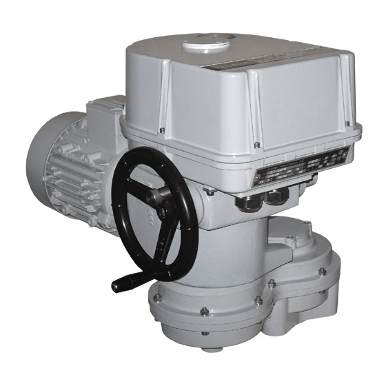
Page 7: Description Of The Actuator
MP 52 200 1.6 Description of the Actuator The actuators MP 52 200 (Fig. 1) consist of the following modules: Module М1 – an electric motor Module M11 – a countershaft box Module М3 – a gearbox with a manual control mechanism Module М4 –... - Page 8 MP 52 200 Obr.2 Module М4 – a control box The following devices are mounted onto the control board place into the control box: · a transmission unit of the control board · a position an indication unit · a torque unit ·...
- Page 9 MP 52 200 Position unit (11) After pressing it is integral with the gearwheel (13) and dismantling is not available. The switching-off tips (53),(54),(56),(57) are screwed into the nuts placed in the positional unit groove. After loosening of the switching-off tip in the nut the tip-nut pair can by moved in the groove.
-
Page 10: Specifications
MP 52 200 Torque switch unit consists of the following parts: Switch element (9) (Fig 3) is formed by two micro- switches S1(20) and S2(21). It is put into operation after loosening of the nut (18)(Fig.3). Cam unit (26)(Fig.3) is formed by two adjustable cams (19) and (22)(Fig.7) placed on the shaft of the torque control... - Page 11 MP 52 200 Other specifications: Protection enclosure of EA: ................IP 55 (STN EN 60 529) ................IP 65 (required to be confimed by the producer) Self-locking: ........guaranteed within 0% till 100% load torque except load torques Power supply:......................230 V AC ±10% Power supply frequency ...................
-
Page 12: Packaging, Transport, Storing And Unpacking
MP 52 200 ·.. EA limit positions (only with computer and ZP2 programme) ·.. way of regulation B) Operation states of controller Error message from error memory: (using LED diodes and RS 232 and personal computer) ·.. control signal missing or faulty ·.. -
Page 13: Liquidation Of The Product And The Package
MP 52 200 After receiving of the EA check whether during their transport or storing no damage occurred. Compare the data on their nameplates with the accompanying documentation/the purchase agreement (the order). In case of any discrepancy, failure or damage inform about the fact the producer immediately. -
Page 14: Dismantling
MP 52 200 · Check whether the connecting flange clings to the valve/gearing. · Fix the flange with four screws tightened to allow moving of EA. Then the fixing screws tighten uniformly crosswisely. 2.1.2 Electric connection and checking of function Follow up with connecting the EA with mains or master system. -
Page 15: Adjusting Of Actuator
MP 52 200 3. Adjusting of actuator Abide by safety measures! · electric switching the electric motor from the manual control status to the electric way of control, · electric blocking of the electric actuator while other mechanisms or devices operate, ·... -
Page 16: Service, Maintenance And Troubleshooting
MP 52 200 · Turn the adjusting trimmer ZERO (Fig. 7) to adjust the output current signal rate measured on the terminals 81-82 to 0 mA or 4mA. · Set the actuator to the position „open“. · Turn the adjusting trimmer GAIN (Fig. 7) to adjust the output current signal rate measured on the terminals 81-82 to 20mA or 5 mA.. -
Page 17: Troubleshooting
MP 52 200 Lubrication: grease HF 401/0 (GLEITM-m) Gearbox oil PP 80 Greasing of the valve spindle is independent on maintenance of the EA! Every six months it is recommended to perform one check move in frame of adjusted operation stroke to verify reliability of functioning with setting back to the original position. -
Page 18: Wiring Diagrams
MP 52 200 4.4 Wiring diagrams... - Page 19 MP 52 200 Legend: Z5a ..connection of single resistive transmitter Z6a ..connection of double resistive transmitter Z10a ..connection of resistive with current converter or capacitive transmitter – 2-wire without supply Z21a ..connection of additional position switches for the EA version with controller Z41a ..connection of space heater and space heater’s terminal switch for EA with controller...
-
Page 20: Dimensional Drawings
MP 52 200 4.5 Dimensional drawings... - Page 21 MP 52 200...
- Page 22 MP 52 200...
Need help?
Do you have a question about the MP 52 200 and is the answer not in the manual?
Questions and answers