
Related Manuals for Regada MO 3


Summary of Contents for Regada MO 3
- Page 1 INSTALLATION, SERVICE AND MAINTENANCE INSTRUCTIONS Electric multi-turn actuators MO 3, MO 3.3, MO 3.4, MO 3.5 ® 74 0992 02...
- Page 2 TEST CERTIFICATE ELECTRIC PART-TURN ACTUATOR MO 3, MO 3.4, MO 3.5 Type number ........Power supply ......V ..Hz Serial number ........Switching-off torque ........Nm Production year ........Adjusted switching - off torque ....Nm Wiring diagram ........Operating speed ........min ............
-
Page 3: Table Of Contents
Please read these instructions carefully before mounting and operating the actuator! Preventive and safety-measures applied on the actuator can not offer required safety level till the actuator and its safety systems are not applied by required and described way and if installation and maintenance is not applied according to applicable instructions and rules! Contents Generally....................................2... -
Page 4: Generally
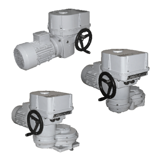
1. Generally 1.1 Purpose and application of the product Electric multi-turn actuators (hereafter referred to as EA), types MO 3, MO 3.3, MO 3.4 resp. MO 3.5 (hereinafter referred as MO) only are high performance electro-mechanical products, designed for direct assembly on controlled devices (regulating bodies - valves, etc.). -
Page 5: Data Specified On Electric Actuator
MO 3, MO 3.3, MO 3.4, MO 3.5 Instructions for stuff training Service can be performed only by workers professionally qualified and trained by the producer or contracted service centre. Warning for safety use Product protection EA MO does not have own short-circuit protection, therefore there must be included suitable protective device into the supply power (circuit breaker, or fuse), which serves at the same time as main switch. -
Page 6: Under-Guarantee And After-Guarantee Service
MO 3, MO 3.3, MO 3.4, MO 3.5 1.5 Under-guarantee and after-guarantee service Our customers are provided with professional service of our firm in installation, operation, service, maintenance, revision and help in troubleshooting for all our products. Under-guarantee service is performed by the service department of the production plant, or by a contracted service centre according to a written claim. -
Page 7: Operation Conditions
MO 3, MO 3.3, MO 3.4, MO 3.5 1.6 Operation conditions 1.6.1 Product location and operation position • Electric actuators may be installed and operated in enclosed locations of industrial facilities with no temperature and moisture regulation, protected from direct climatic effects (such as direct sunlight). -
Page 8: Power Supply And Operating Mode
MO 3, MO 3.3, MO 3.4, MO 3.5 • with relative humidity 5 to 100 %, including the condensation of up to 0,025 kg water content per 1 kg of dry air at 27 °C, at above stated temperature ..................AB 2+AB 5* •... -
Page 9: Conservation, Packing, Transport, Storing And Unpacking
MO 3, MO 3.3, MO 3.4, MO 3.5 1.7 Conservation, packing, transport, storing and unpacking Surfaces without surface treatment are treated by conservation preparation MOGUL LV 2-3 before packaging . Conservation is not necessary if the following storage conditions are complied with: •... -
Page 10: Description, Function And Technical Parameters
MO 3, MO 3.3, MO 3.4, MO 3.5 2. Description, function and technical parameters 2.1 Description and function Electric multi-turn actuators MO consist of these modules (Fig.1): Module M 1 – electric-motor Module M11 – countershaft transmission with rotary hold Module M 3 –... - Page 11 MO 3, MO 3.3, MO 3.4, MO 3.5 Fig.2 Module M 4 – control box (Fig. 1) Control box is in upper part of electric actuator and forms individual function unit. The top part is formed by the cover with opening and monitoring window of position indicator.
- Page 12 MO 3, MO 3.3, MO 3.4, MO 3.5 Fig.3 Position unit EA is equipped with a position step unit that provides for limiting the EA end positions with electric control by means of S3, S4 position switches. The drive for the position unit is derived from EA output shaft by means of idle gears.
- Page 13 MO 3, MO 3.3, MO 3.4, MO 3.5 Torque unit (Fig. 4 and 5) is composed of three functional sub-units: • torque disk (Fig. 4) The limit of • torque unit (Fig. 5) • locking mechanism (82) (Fig. 5) min. torque Torque disk (Fig.
-
Page 14: Technical Data
MO 3, MO 3.3, MO 3.4, MO 3.5 Controller EA of the MO with controller type are equipped with an electronic controller intended for controlling EA by means of input standardized signals. Reversing contactors According to specification, EA can involve also reversing contactors for switching on and reversing a three-phases EA electric motor. - Page 15 MO 3, MO 3.3, MO 3.4, MO 3.5 Table Nr. 1 Electric motor Switching - off Number of Operating Type/ 5)10) Nominal revolutions speed type torque ±10[%] Supply voltage ±10 [%] number power speed current [V] ±10% [min revolutions [Nm]...
- Page 16 MO 3, MO 3.3, MO 3.4, MO 3.5 Output part backlash: ..............< 5 °at the load by 5% value switching of torgue Heating element (E1) Heating resistor – supply voltage: ....................max. 250 V AC; Heating output: .......................... about W/55°C Thermo-switch of heating element (F2) Supply voltage: ..........................230 V AC, 5 A...
- Page 17 1) of the transmitter’s nominal value related to output values with max. revolutions setting for the given stroke degree according to table 3 Electronic position controller (N) „REGADA" ( Valid for the EA MO version with controller only) Controller software equipment:...
-
Page 18: Mechanical Connection
MO 3, MO 3.3, MO 3.4, MO 3.5 ............................. current 4 up to 20 mA Power outputs: ........................2x relay 5A/250V AC Digital outputs: .....4x LED (supply, error, adjustment, "opening", "closing" - with two-colour LED) Error status: ....................... control switch 24 V, 2W - POR Reaction at error situation: transmitter error - error message LED Control signal missing: ...................... -
Page 19: Installation And Dismantling Of Actuator
MO 3, MO 3.3, MO 3.4, MO 3.5 3. Installation and dismantling of actuator Abide by safety measures! Notes: Repeatedly verify whether placing of EA correspondents to part "Operating conditions". If actual conditions differ from recommended, it is necessary to consult it with manufacturer. -
Page 20: Electric Connection To The Network, Respectively Control System
MO 3, MO 3.3, MO 3.4, MO 3.5 3.1.2 Electric connection to the network, respectively control system Consequently perform electric connection to the network, respectively to joining system. 1. Adhere to instructions stated in chapter 1.2 Safety instructions – Requirements for professional.. -
Page 21: Disassembly
MO 3, MO 3.3, MO 3.4, MO 3.5 Check of position switches (Fig.6,8). When the actuator moves towards "close" switch over contacts of switches S4 resp. S6 by pressing of disconnecting bell of relevant switch. If the connection is properly performed, the actuator must stop when contacts of switch S4 are switched over and light up when contacts of switch S6 are switched over. -
Page 22: Adjusting
MO 3, MO 3.3, MO 3.4, MO 3.5 4. Adjusting Attention! See chapter 1.2 If it is necessary to connect the supply voltage to Electric actuator, make sure by following the mentioned procedure that there is no injury caused by the electric current. Otherwise, disconnect the... -
Page 23: Position Switches Adjustment (S3(S13),S4(S14) (Fig. 6)
MO 3, MO 3.3, MO 3.4, MO 3.5 4.2 Position switches adjustment (S3(S13),S4(S14) (Fig. 6) EA is delivered set to a stroke corresponding to according to table 3 or to a stroke required by customer. The stroke referred on the type label of EA corresponds to the maximum stroke with the gear unit set to 11 according to table 3. - Page 24 MO 3, MO 3.3, MO 3.4, MO 3.5 TABLE 3 MAX. EA WORKING REVOLUTIONS (provided customer doesn´t specify otherwise, EA will be set to 6 by producer) STROKE STAGE MO 3 MO 3.3 MO 3.4 MO 3.5 1,75 1,75 10,5...
-
Page 25: Signaling Switches Adjustment (S5,S6) (Fig. 8)
MO 3, MO 3.3, MO 3.4, MO 3.5 4.3 Signaling switches adjustment (S5,S6) (Fig. 8) The signaling switches of EA are at producer preset to switch on about 10% before end positions provided the customer not specified otherwise. Before proceeding with signaling switches adjustment, S3, S4 end position switches must be adjusted according to the previous chapter if necessary. -
Page 26: Adjustment Of Resistant Transmitter (Fig.9)
MO 3, MO 3.3, MO 3.4, MO 3.5 4.5 Adjustment of resistant transmitter (Fig.9) Function of resistance transmitter: - remote position indicator - feedback for controller (valid for Electric actuator with controller) - remote position indicator with converter. Before the resistant transmitter adjustment the position switches have to be adjusted. Adjustment consists in setting of the resistance in the defined limit position of the EA. -
Page 27: Adjustment Of The Electronic Position Transmitter (Epv) - The Resistive Transmitter (Potentiometer) With The Converter Ptk 1
MO 3, MO 3.3, MO 3.4, MO 3.5 4.6 Adjustment of the Electronic Position Transmitter (EPV) - the Resistive Transmitter (Potentiometer) with the Converter PTK 1 4.6.1 EPV – the 2-wire version (Fig. 10) The position transmitter with the converter PTK1 is in the plant adjusted to have the output current signal on the terminals 81-82 as follows: •... -
Page 28: Adjustment Of Capacitive Transmitter Cpt1/A (Fig.12)
MO 3, MO 3.3, MO 3.4, MO 3.5 Note: The output signal of (0-20mA, 4-20mA or 0-5mA - according to the specification) can be adjusted at the range from 85 up to 100% of the rated stroke according to table Nr.3. At values less than 85% the value of the output signal is reduced proportionally. - Page 29 MO 3, MO 3.3, MO 3.4, MO 3.5 C.) Adjustment of the Capacitive Transmitter Served as a Feedback of the Position Controller (EA MO with controller) While checking or adjusting the output signal of 4÷20 mA follow these steps: •...
-
Page 30: Adjustment Of Position Controller (Fig. 13)
Laying of adjusters and signaling elements on the board of the REGADA controller is shown on Fig. 13: SW1 button... -
Page 31: Watching Operation And Error States
MO 3, MO 3.3, MO 3.4, MO 3.5 Standard setting of controller (programmed RESET of controller) – In the case of problems with setting the parameters, proceed as follows: - disconnect the supply voltage - at the same time, press buttons SW1 and SW2... -
Page 32: Local Electric Control (Fig.14)
MO 3, MO 3.3, MO 3.4, MO 3.5 4.9 Local electric control (Fig.14) Additional accessories In case of necessity (set up, functional check, etc.) but at provided supply is possible to adjust the EA by local electric control. After switch over of mode selector to the mode „LOCAL“... - Page 33 MO 3, MO 3.3, MO 3.4, MO 3.5 Lubrication: • the gearbox: in versions with temperatures –25°C till +55°C - Madit PP-80 (Slovnaft) in versions with temperatures –40°C till +40°C - Avia SYNTOGEAR PE 68 • gears of transmission unit and drive mechanism on the control board: - in versions with temperatures -25°C till +55°C - grease µ...
-
Page 34: Troubleshooting
MO 3, MO 3.3, MO 3.4, MO 3.5 5.3 Troubleshooting At failure of power supply the EA stops in the position where it was before the failure. If needed the EA can be set only with the manual control (the hand wheel). After restoration of power the EA is prepared for operation. -
Page 35: Enclosures
MO 3, MO 3.3, MO 3.4, MO 3.5 7. Enclosures Wiring diagrams Wiring diagrams MO... - Page 36 MO 3, MO 3.3, MO 3.4, MO 3.5...
- Page 37 MO 3, MO 3.3, MO 3.4, MO 3.5 Wiring diagrams MO with controller...
- Page 38 MO 3, MO 3.3, MO 3.4, MO 3.5 Legend: Z279a ....connection of 3-phase electric motor without contactors Z279c ....connection of 3-phase electric motor with thermal protection Z297a ....connection of 3-phase electric motor with contactors Z297b ....connection of 3-phase electric motor with reverse contactors and thermal protection Z403a ....
-
Page 39: Switch Operation Chart
MO 3, MO 3.3, MO 3.4, MO 3.5 7.2 Switch operation chart Open close Switch terminals operating stroke 11 (M2) - 12 12 - 14 15 (М3) – 16 16 – 18 19 – 20 20 - 22 23 – 24 24 - 26 27 –... -
Page 40: Dimension Drawings And Mechanic Connections
MO 3, MO 3.3, MO 3.4, MO 3.5 Dimension drawings and mechanic connections Note: For these types of EA in all versions are valid dimensions marked *. Dimension drawings for EA MO 3 Mechanic connections for EA MO 3 without connect adapter 5 x tooth... - Page 41 MO 3, MO 3.3, MO 3.4, MO 3.5 4 x tooth F10 – shape D F10 – shape C; DIN 3338 F10 – shape E; ISO 5210...
- Page 42 MO 3, MO 3.3, MO 3.4, MO 3.5 Mechanic connections for EA MO 3...
- Page 43 MO 3, MO 3.3, MO 3.4, MO 3.5...
- Page 44 MO 3, MO 3.3, MO 3.4, MO 3.5 Mechanic connections for EA MO 3 with connect adapter F10 – shape A F14 – shape C F10 – shape B1 ; ISO 5210...
- Page 45 MO 3, MO 3.3, MO 3.4, MO 3.5 Dimension drawings for EA MO 3.5...
- Page 46 MO 3, MO 3.3, MO 3.4, MO 3.5 Dimension drawings for EA MO 3.4...
- Page 47 MO 3, MO 3.3, MO 3.4, MO 3.5 Dimension drawings for EA MO 3.3...
- Page 48 MO 3, MO 3.3, MO 3.4, MO 3.5 Mechanic connections for EA MO 3.3 without connect adapter shape 5 tooth 35°/37°; GOST R 55510 shape C; DIN 3338...
- Page 49 MO 3, MO 3.3, MO 3.4, MO 3.5 Mechanic connections for EA MO 3.4 without connect adapter shape C; DIN 3338 5 tooth 35°/37° ; GOST R 55510 shape D shape B2 ; ISO 5210...
- Page 50 MO 3, MO 3.3, MO 3.4, MO 3.5 Mechanic connections for EA MO 3.4 with connect adapter...
- Page 51 MO 3, MO 3.3, MO 3.4, MO 3.5...
- Page 52 MO 3, MO 3.3, MO 3.4, MO 3.5 Mechanic connections EA MO 3.5 without connect adapter shape C; DIN 3338 shape 5 tooth 35°/37°; GOST R 55510 shape D shape B1; B2, B3; ISO 5210...
- Page 53 MO 3, MO 3.3, MO 3.4, MO 3.5 Mechanic connections for EA MO 3.5 with connect adapter F14 – shape A; ISO 5210...
-
Page 54: Guarantee Service Check Report
MO 3, MO 3.3, MO 3.4, MO 3.5 7.4 Guarantee service check report Service center: Date of repair: Guarantee repair no.: User of actuator: Claim applied by: Actuator type number: Actuator production number: Product claim fault: Detected product fault: Used spare parts:... -
Page 55: Post Guarantee Service Check Report
MO 3, MO 3.3, MO 3.4, MO 3.5 7.5 Post guarantee service check report Service center: Date of repair: User of actuator: Actuator operating place : Actuator type number: Actuator production number: Detected product fault: Used spare parts: Remarks: Issued on a day:... -
Page 56: Commercial Representation
080 01 Prešov Tel.: +421 (0)51 7480 460, Fax: +421 (0)51 7732 096, E-mail: regada@regada.sk Czech Republic: Exclusive representation Regada, s.r.o. (Ltd.) for sale of electric actuators Regada Česká, s.r.o. Nám. 5. května 17, 252 25 Jinočany, PRAHA – západ, Tel.: +420 257 961 302...
Need help?
Do you have a question about the MO 3 and is the answer not in the manual?
Questions and answers