
Related Manuals for Falcon E2011


Summary of Contents for Falcon E2011
- Page 1 User, Installation and Servicing Instructions REGENERATION OVEN E2011 Read these instructions before use DATE PURCHASED: MODEL NUMBER: SERIAL NUMBER: DEALER: SERVICE PROVIDER: T101094 Rev No: 1...
- Page 2 Dear Customer Thank you for choosing Falcon Foodservice Equipment. This manual can be downloaded from www.falconfoodservice.com or scan here: IMPORTANT: Please keep this manual for future reference. Falcon Foodservice Equipment HEAD OFFICE Wallace View, Hillfoots Road, Stirling, FK9 5PY, Scotland...
-
Page 3: Table Of Contents
CONTENTS SYMBOLS ........................... 5 SAFETY GUIDANCE ........................6 GENERAL SAFETY ......................... 6 INSTALLATION SAFETY ......................7 ELECTRICAL SAFETY ......................7 FIRE SAFETY .......................... 7 MAINTENANCE SAFETY......................8 APPLIANCE INFORMATION ...................... 2 OPERATION ..........................3 COMPONENT PARTS & CONTROLS ..................3 USING THE APPLIANCE ...................... - Page 4 9.10 RELAY, CONTACTOR & FUSE REMOVAL AND REFITTING ..........18 9.11 OPERATING THERMOSTAT REMOVAL ................19 9.12 DOOR PROXIMITY SWITCH REMOVAL ................20 9.13 OVEN SAFETY THERMOSTAT RESET ................20 9.14 SAFETY THERMOSTAT REMOVAL .................. 21 9.15 HEATING ELEMENTS REMOVAL ..................22 9.16 FAN REMOVAL ........................
-
Page 5: Symbols
1.0 SYMBOLS SCREWDRIVER SPANNER COOKING OIL GREASE WARNING SPARK IGNITION FLAME VIEWPORT ALLEN KEY IGNITER C SPANNER REMOVE DEVICE WARNING READ MANUAL FIRE RISK PLUG REMOVER ELECTRICAL... -
Page 6: Safety Guidance
2.0 SAFETY GUIDANCE 2.1 GENERAL SAFETY 2.1.1 These instructions are only valid if the country code appears on the appliance. If the code does not appear on the appliance, refer to the technical instructions for adapting the appliance to the conditions for use in that country. 2.1.2 These appliances have been UKCA/CE-marked based on compliance with the Electrical Equipment (safety) Regulations/LVD Directives and Electromagnetic... -
Page 7: Installation Safety
2.2 INSTALLATION SAFETY 2.2.1 Installation must meet national or local regulations. Attention must be paid to: safety (installation & use) regulations, health and safety at work act, local and national building regulations, fire precautions act. 2.2.2 The installer must instruct the responsible person(s) of the correct operation and maintenance of the appliance. -
Page 8: Maintenance Safety
2.5.8 If the thermostats or capillaries are damaged then do not turn the appliance on and contact Falcon or you approved service provider to undertake the necessary repairs. 2.5.9 To obtain maximum performance from this unit regular servicing of the appliance should be undertaken to ensure correct operation, it is functioning as intended, and safe to use. - Page 9 IMPORTANT INFORMATION ELECTRICAL SAFETY ADVICE REGARDING SUPPLEMENTARY ELECTRICAL PROTECTION Commercial kitchens and foodservice areas are environments where electrical appliances may be located close to liquids, or operate in and around damp conditions or where restricted movement for installation and service is evident. The installation and periodic inspection of the appliance should only be undertaken by a qualified, skilled and competent electrician;...
-
Page 10: Appliance Information
3.0 APPLIANCE INFORMATION These appliances have been UKCA/CE-marked based on compliance with the Electrical Equipment (safety) Regulations/LVD Directives and Electromagnetic Compatibility (EMC) Regulations/Directives for the Countries as stated on the data plate. A - Serial No B - Model No C –... -
Page 11: Operation
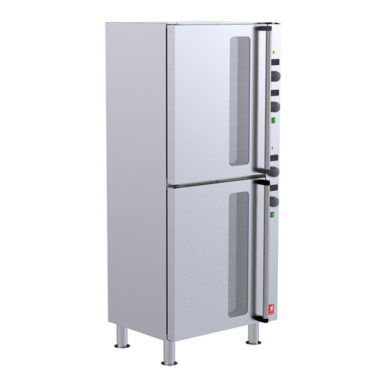
4.0 OPERATION 4.1 COMPONENT PARTS & CONTROLS Upper oven door Oven shelf support Control panel Oven shelf Upper oven heat neon (Amber) Lower oven door Upper oven temperature control Lower oven heat neon (Amber) Upper Oven timer control Lower oven temperature control Upper oven on/off switch (Green) Lower Oven timer control Components access panel... -
Page 12: Using The Appliance
4.2 USING THE APPLIANCE The regeneration oven has been factory set for the cooking of pre-chilled and frozen bulk food meals. 4.2.1 Plug in the appliance. 4.2.2 Each oven can be powered on using the green illuminated switch. 4.2.3 The temperature can be adjusted between 70°C and 200°C, turning the temperature control knob right will increase the temperature, left will decrease. -
Page 13: Cleaning And Maintenance
5.0 CLEANING AND MAINTENANCE When removing heavy items to aid cleaning or maintenance particular care should be taken. A manual handling risk assessment is the best way to determine the level of risk to anyone using or maintaining this equipment. To help with such an evaluation we have included the weights of individual components that may present significant risk. -
Page 14: Cleaning
57 must be used for connection to a 400V 3N~ supply. Only use Falcon approved spare parts. When ordering spare parts, please quote model number; serial number stated. This information will be found on data plate attached to the appliance rear. -
Page 15: Specification
6.0 SPECIFICATION 6.1 APPLIANCE WEIGHT TABLE APPLIANCE UNIT WEIGHT (kg) PACKED WEIGHT (kg) E2011 6.2 TECHNICAL DATA TABLE(S) MODEL: E2011 CURRENT POWER MAX (A) @ ACTUAL (A) @ PHASE MIN (A) @ 230V (kW) @ 230V 230V 230V 12.96 15.12 14.4... -
Page 16: Dimensions / Connection Locations
7.0 DIMENSIONS / CONNECTION LOCATIONS... -
Page 17: Installation
8.0 INSTALLATION WARNING: USE THE LIFTING AIDS/MANUAL HANDLING EQUIPMENT TO REMOVE THE APPLIANCE FROM PALLET AND FOR MANOEUVRING THE APPLIANCE EITHER IT’S ON OR OFF THE PALLET DUE TO IT’S WEIGHT AND HEIGHT. CARE MUST BE TAKEN WHILST HANDLING SHEET METAL. UNLESS OTHERWISE STATED, PARTS WHICH HAVE BEEN PROTECTED BY THE MANUFACTURER ARE NOT TO BE ADJUSTED BY THE INSTALLER. -
Page 18: Sitting / Clearances
The provision of RCDs and supplementary bonding must be specified by the host organization’s appointed installation designer or electrical contractor and installed by a suitably qualified and competent electrician so as to comply with Regulations 419.2 and 544.2 8.1 SITTING / CLEARANCES This appliance must be installed on firm level floor in a well-lit position. -
Page 19: Assembly
ASSEMBLY 8.2.1 Position the appliance and level using feet adjusters as shown below. 8.2.2 Appliance must be secured to the floor or rear wall/object by using at least one of the following options: • Fix the appliance to the floor by using fixing points provided with unit feet. •... -
Page 20: Commissioning
Live 1 (Phase 1) Brown Live 2 (Phase 2) Black Live 3 (Phase 3) Grey Neutral Blue Earth Yellow/Green THIS APPLIANCE MUST BE EARTHED This appliance is also provided with a terminal for connection of an external equipotential conductor. This terminal is an effective electrical contact with all fixed exposed metal parts of the appliance and shall allow the connection of conductor having a nominal cross-section area of up to 10mm². -
Page 21: Instruction To User
8.5 INSTRUCTION TO USER Warning: To avoid scalding, do not use the containers filled with liquid or food which, through cooking become fluid, at levels higher than those which can be observed. 8.5.1 After installation and commissioning is completed, please hand the user instructions to the user and ensure that the person(s) responsible understand the instructions regarding correct operation and cleaning of the appliance. -
Page 22: Servicing
9.0 SERVICING BEFORE ATTEMPTING ANY MAINTENANCE, ISOLATE THE APPLIANCE AT THE MAINS SWITCH AND TAKE STEPS TO ENSURE THAT IT IS NOT INADVERTENTLY SWITCHED ON. MAINTENANCE CHECK Regular servicing of the appliance should be undertaken to ensure correct operation, it is functioning as intended, and safe to use. -
Page 23: To Replace Door Stud
TO REPLACE DOOR STUD 9.4.1 Unlock nut and remove stud. 9.4.2 Replace stud to ensure a tight seal prior to tightening nut. CONTROL PANEL REMOVAL BEFORE ATTEMPTING ANY MAINTENANCE, ISOLATE THE APPLIANCE AT THE MAINS SWITCH AND TAKE STEPS TO ENSURE THAT IT IS NOT INADVERTENTLY SWITCHED ON. -
Page 24: Side Service Access Panel Removal
SIDE SERVICE ACCESS PANEL REMOVAL BEFORE ATTEMPTING ANY MAINTENANCE, ISOLATE THE APPLIANCE AT THE MAINS SWITCH AND TAKE STEPS TO ENSURE THAT IT IS NOT INADVERTENTLY SWITCHED ON. 9.6.1 Loosen two screws at top of access panel. Remove three screws from sides and bottom of access panel. -
Page 25: To Replace Temperature/Timer Encoder
TO REPLACE TEMPERATURE/TIMER ENCODER 9.8.1 Detach encoder connector from temperature/timer module and remove the encoder as shown below. 9.8.2 Replace in reverse order. Reconnect the connector to temperature/control module securely. -
Page 26: To Replace Neon/Led
TO REPLACE NEON/LED BEFORE ATTEMPTING ANY MAINTENANCE, ISOLATE THE APPLIANCE AT THE MAINS SWITCH AND TAKE STEPS TO ENSURE THAT IT IS NOT INADVERTENTLY SWITCHED ON. 9.9.1 Pull out and rotate control panel as per step 9.5. 9.9.2 Remove wires from neon, undo nut on inside of control panel and withdraw neon. 9.9.3 Replace in reverse order. -
Page 27: Operating Thermostat Removal
Fuse: 9.10.5 Remove side access panel as per step 9.6. or Remove Control Panel as per 9.5 to access the fuses. 9.10.6 When replacing, it is essential to use a fuse of correct type and rating. 9.11 OPERATING THERMOSTAT REMOVAL BEFORE ATTEMPTING ANY MAINTENANCE, ISOLATE THE APPLIANCE AT THE MAINS SWITCH AND TAKE STEPS TO ENSURE THAT IT IS NOT INADVERTENTLY SWITCHED ON. -
Page 28: Door Proximity Switch Removal
9.12 DOOR PROXIMITY SWITCH REMOVAL 9.12.1 Pull out and rotate control panel as per step 9.5. 9.12.2 Detach proximity switch cable from wago connectors. 9.12.3 Fix spanner on proximity switch and on nut behind chamber front panel and turn to remove switch. -
Page 29: Safety Thermostat Removal
9.13.1 An overheat safety trip is fitted to the oven. Access is at the rear of the appliance as shown. To reset, press button. (See warning note below). Warning: If safety trip has been activated, reason for overheating must be identified before returning the appliance to service. -
Page 30: Heating Elements Removal
9.14.6 When re-fitting, ensure all electrical connections are as per wiring diagram. 9.15 HEATING ELEMENTS REMOVAL BEFORE ATTEMPTING ANY MAINTENANCE, ISOLATE THE APPLIANCE AT THE MAINS SWITCH AND TAKE STEPS TO ENSURE THAT IT IS NOT INADVERTENTLY SWITCHED ON. 9.15.1 Open door and remove all shelves from oven chamber. 9.15.2 9.15.2 Thumb... -
Page 31: Fan Removal
9.16 FAN REMOVAL 9.16.1 Open door, remove shelves, shelf support and fan cover panel from oven chamber as per step 9.15. 9.16.2 Remove element surrounding fan that is to be replaced. 9.16.3 9.16.4 9.16.6 9.16.3 Remove fixing nut from Impellor (note: Impellor nut is a left-hand thread). 9.16.4 Remove three screws holding fan mounting plate in position, then carefully pull fan with cables still attached through fan opening in rear of oven chamber (ensure not to tear or cut the cables when feeding through). -
Page 32: Manual Programing Of Temperature Control
9.17 MANUAL PROGRAMING OF TEMPERATURE CONTROL In the event of the temperature module losing its parameters these settings can be manually set on the module using the following procedure: 9.17.2 / 9.17.15 9.17.1 Make sure the device is off by pressing the knob for 2 seconds, then release Push and hold in temperature knob for 4 seconds;... -
Page 33: Manual Programing Of Timer Control
9.18 MANUAL PROGRAMING OF TIMER CONTROL 9.18.2 /9.18.14 9.18.1 Make sure the device is off by pressing the knob for 2 seconds, then release. Push and hold in timer control knob for 4 seconds; the display will show “PA”. 9.18.2 9.18.3 Push the knob once to select. -
Page 34: Circuit Diagrams
9.19 CIRCUIT DIAGRAMS 9.19.1 TOP & BOTTOM OVEN... -
Page 35: Wiring Diagrams
9.20 WIRING DIAGRAMS 9.20.1 TOP & BOTTOM OVEN Top & Btm oven Ter. strips linked, see oven linked Wiring... - Page 36 9.20.2 OVEN LINK WIRING...
-
Page 37: Fault Finding
10.0 FAULT FINDING FAULT POSSIBLE CAUSES REMEDY USER *ENG Check mains power is ✓ Unit will not turn ON No power to unit connected and turned on. ✓ Unit will not turn ON Fuses blown Call engineer ✓ Safety stat tripped Call engineer Oven will not operate ✓... -
Page 38: Spare Parts
11.0 SPARE PARTS Item No. SPARES PART DESCRIPTION NUMBER Amber Neon 730962040 Temperature Controller Module 730980001 Encoder 730980003 Control knob 730980005 Timer Control Module 730980002 On / Off Switch (Green) 730910020 Fuse 1A Anti-Surge 732150024 Door proximity switch 730980019 Relay 731570004 Contactor 734510010... -
Page 39: Service Information
1. Model number – found on data plate 2. Serial number – found on data plate 3. Brief description of the issue To contact Falcon for a warranty issue dial (UK only) 01786 455 200 and select Warranty Issues from the menu.
Need help?
Do you have a question about the E2011 and is the answer not in the manual?
Questions and answers