Table of Contents
Advertisement
Quick Links
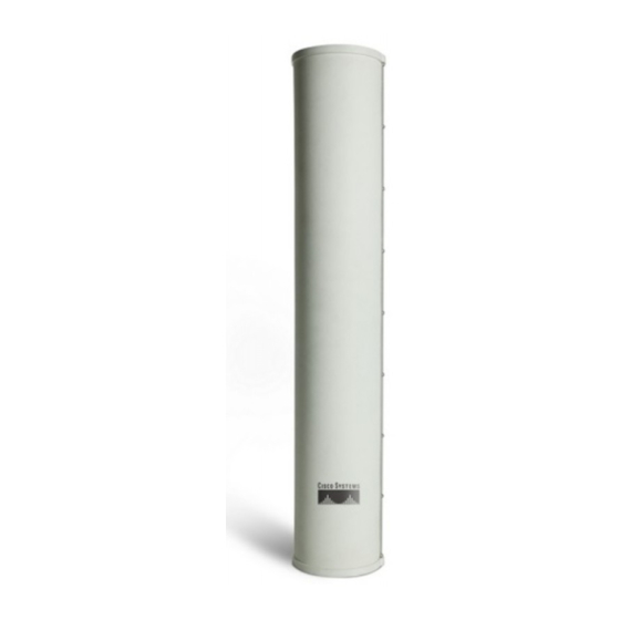
Cisco Aironet 14-dBi Vertically Polarized Sector
Antenna (AIR-ANT2414S-R)
This document outlines the specifications, describes the AIR-ANT2414S-R 14-dBi vertically polarized
sector antenna, and provides instructions for mounting and aligning it. The antenna operates in the
2.4-GHz frequency range and is designed for use in bridging environments. The antenna is designed to
be used outdoors and can be mounted on 1.5 in. (3.8 cm) to 2.5 in. (6.3 cm) diameter masts.
The following information is provided in this document.
•
Technical Specifications, page 2
System Requirements, page 3
•
•
Safety Precautions, page 3
Installation Notes, page 4
•
•
Obtaining Documentation and Submitting a Service Request, page 11
Corporate Headquarters:
Cisco Systems, Inc., 170 West Tasman Drive, San Jose, CA 95134-1706 USA
Copyright © 2004 Cisco Systems, Inc. All rights reserved.
Advertisement
Table of Contents

Related Manuals for Cisco Aironet AIR-ANT2414S-R


Summary of Contents for Cisco Aironet AIR-ANT2414S-R
- Page 1 2.4-GHz frequency range and is designed for use in bridging environments. The antenna is designed to be used outdoors and can be mounted on 1.5 in. (3.8 cm) to 2.5 in. (6.3 cm) diameter masts. The following information is provided in this document.
-
Page 2: Technical Specifications
7.5 lb. (3.4 kg) Operating temperature range –22°F to 158°F) (–30°C to 70°C Storage temperature range –40°F to 185°F (–40°C to 85°C) Wind rating 100 mph (161 kph) H-Plane Radiation Pattern E-Plane Radiation Pattern Cisco Aironet 14-dBi Vertically Polarized Sector Antenna (AIR-ANT2414S-R) 78-16403-01... -
Page 3: System Requirements
System Requirements This antenna is designed for use with Cisco Aironet access points and bridges but can be used with any 2.4-GHz Cisco Aironet radio device that utilizes an RP-TNC connector. To meet regulatory restrictions, if you are using this antenna with a Cisco Aironet 1300 Series Wireless Note Bridge, the antenna must be professionally installed. -
Page 4: Installation Notes
Each person should be assigned to a specific task, and should know what to do and when to do it. One person should be in charge of the operation to issue instructions and watch for signs of trouble. -
Page 5: Installation Process
Generally, the higher an antenna is above the ground, the better it performs. Good practice is to install your antenna about 5 to 10 ft (1.5 to 3 m) above the roof line and away from all power lines and obstructions. - Page 6 Follow these steps to attach the mounting brackets to the antenna. Step 1 Position the antenna so that the arrow on the orientation label is pointed up. The arrow points to the top of the antenna so that it can be installed correctly.
-
Page 7: Mounting The Antenna
Note that the adjustable bracket is in the top position. Depending on how your mast is configured, you may need to remove one of the mast mount clamps in order to mount the antenna. -
Page 8: Aligning The Antenna
If you removed the outside mast mount clamp on the top bracket, reinstall it now. Make sure you have Step 2 retained the ¼-20 flat washers and split lock washers on the hex head bolts and start a ¼-20 hex nut on each bolt. - Page 9 The goal when positioning a directional antenna is to align the local antenna for maximum received signal strength using the LED indications. The LEDs are convenient and easy to use. Normally, you observe a single large peak as you pan the antenna across the signal path. Think of the receive signal as a target (see...
-
Page 10: Grounding The Antenna
When you are using LEDs to maximize the signal, adjust the antenna until as many LEDs as possible are on and the rest are blinking as fast as possible. With all three LEDS on, the signal is good enough to support the maximum data rate. -
Page 11: Suggested Cable
Drill a hole in the building’s wall as close as possible to the equipment to which you will connect the Step 4 lead-in cable. There may be wires in the wall. Make sure your drilling location is clear of any obstructions or other Caution hazards. - Page 12 Cisco and the Cisco Logo are trademarks of Cisco Systems, Inc. and/or its affiliates in the U.S. and other countries. A listing of Cisco's trademarks can be found at www.cisco.com/go/trademarks. Third party trademarks mentioned are the property of their respective owners. The use of the word partner does not imply a partnership relationship between Cisco and any other company.
Need help?
Do you have a question about the Aironet AIR-ANT2414S-R and is the answer not in the manual?
Questions and answers