Table of Contents
Advertisement
Quick Links
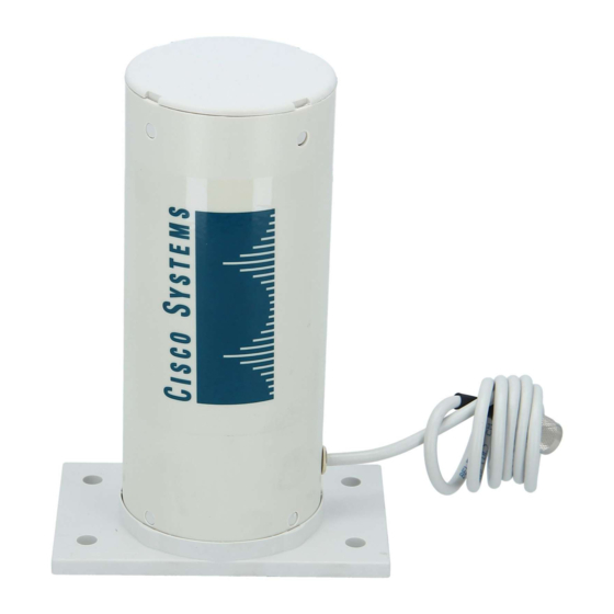
Cisco Aironet 10-dBi Yagi Antenna
(AIR-ANT2410Y-R)
This document describes the AIR-ANT2410Y-R 10-dBi Yagi antenna and provides instructions for
mounting it. The antenna operates in the 2.4- to 2.48-GHz frequency range and is designed for use as an
access point or bridge antenna. The antenna is an enclosed 6-element, vertically polarized directional
Yagi and is designed to be mounted indoors or outdoors on a mast or flat vertical surface.
The following information is provided in this document.
•
Technical Specifications, page 2
Safety Precautions, page 3
•
•
Installation Notes, page 4
Translated Safety Warnings, page 9
•
•
Obtaining Documentation and Submitting a Service Request, page 10
Corporate Headquarters:
Cisco Systems, Inc., 170 West Tasman Drive, San Jose, CA 95134-1706 USA
© 2006 Cisco Systems, Inc. All rights reserved.
Advertisement
Table of Contents

Related Manuals for Cisco Aironet AIR-ANT2410Y-R


Summary of Contents for Cisco Aironet AIR-ANT2410Y-R
- Page 1 This document describes the AIR-ANT2410Y-R 10-dBi Yagi antenna and provides instructions for mounting it. The antenna operates in the 2.4- to 2.48-GHz frequency range and is designed for use as an access point or bridge antenna. The antenna is an enclosed 6-element, vertically polarized directional Yagi and is designed to be mounted indoors or outdoors on a mast or flat vertical surface.
-
Page 2: Technical Specifications
Technical Specifications Antenna type Yagi Operating frequency range 2400 – 2485 MHz Nominal input impedence 50Ω VSWR < 1.5:1 (VSWR) Gain 10 dBi Polarization Vertical or horizontal, linear Horizontal plane 3 dB 55° beamwidth Vertical plane 3 dB 55° beamwidth... -
Page 3: System Requirements
Each person should be assigned to a specific task, and should know what to do and when to do it. One person should be in charge of the operation to issue instructions and watch for signs of trouble. -
Page 4: Installation Notes
Step 3 If you lose control of the mast while raising it, make sure that it does not fall in the wrong direction. Use a durable non-conductive rope secured at each 2-foot level as the mast is raised. Have an assistant tend the rope, ready to pull the mast clear of any hazards (such as power lines) if it begins to fall. -
Page 5: Choosing A Mounting Location
Generally, the higher an antenna is above the ground, the better it performs. Good practice is to install your antenna about 5 to 10 ft (1.5 to 3 m) above the roof line and away from all power lines and obstructions. -
Page 6: Mounting The Antenna
The antenna can also be mounted on a wall or other flat vertical surface. Mounting hardware is not Note provided. The following section contains a typical procedure for installing the antenna on a mast. Your installation may vary. Before you begin, you may want to refer to Figure 1. -
Page 7: Mounting On A Mast
Step 3 Make sure the antenna is positioned so that the arrow labelled V-POL is pointing up. The uncovered drain holes will on at the bottom of the antenna radome and the covered drain holes will be on the side. -
Page 8: Mounting On A Wall
Follow these steps to change to the horizontal mode: Step 1 Use a 5/32-in (4 mm) hex allen wrench to remove the 4 cap screws from the base of the antenna. Step 2 Rotate the antenna so that the arrow labelled H-POL is pointing up. The two covered drain holes will be on the bottom of the antenna radome and the two uncovered drain holes will be on the side. -
Page 9: Suggested Cable
Start the fasteners into the holes. Step 6 Use a suitable wrench to secure the assembly to the surface and tighten the fasteners. Do not overtighten. Step 7 Apply the danger label to a plainly visible area adjacent to the antenna. -
Page 10: Statement 332-Antenna Installation Warning
Subscribe to the What’s New in Cisco Product Documentation as a Really Simple Syndication (RSS) feed and set content to be delivered directly to your desktop using a reader application. The RSS feeds are a free service and Cisco currently supports RSS Version 2.0. - Page 11 Cisco and the Cisco Logo are trademarks of Cisco Systems, Inc. and/or its affiliates in the U.S. and other countries. A listing of Cisco's trademarks can be found at www.cisco.com/go/trademarks. Third party trademarks mentioned are the property of their respective owners. The use of the word partner does not imply a partnership relationship between Cisco and any other company.
- Page 12 Cisco Aironet 10-dBi Yagi Antenna (AIR-ANT2410Y-R) 78-16122-01...
Need help?
Do you have a question about the Aironet AIR-ANT2410Y-R and is the answer not in the manual?
Questions and answers