
Related Manuals for Emerson Fisher FIELDVUE DVC7K-H


Summary of Contents for Emerson Fisher FIELDVUE DVC7K-H
- Page 1 Quick Start Guide D104766X012 May 2024 Fisher™ FIELDVUE™ DVC7K-H Digital Valve Controller...
-
Page 2: Table Of Contents
Smart Wireless THUM Adapter ................. 32 Section 6: Local User Interface (LUI) Flow Chart Overview ........................ 33 Configure ....................... 34 Service Tools ......................35 Section 7: Configure the Digital Valve Controller Configuration Using the LUI ................35 Configuration Using an Emerson Handheld Communicator ..... 40... -
Page 3: Section 1: Related Documents
38. The instrument must be powered with at least 10 volts and 4 mA to operate the LUI. You can also setup and calibrate the instrument using an Emerson handheld communicator or with a personal computer with AMS Device Configurator. For information on using the software with a FIELDVUE instrument, refer to the appropriate user guide or help. - Page 4 DVC7K-H Digital Valve Controller Quick Start Guide May 2024 D104766X012 WARNING Avoid personal injury or property damage from sudden release of process pressure or bursting of parts. Before proceeding with any Installation procedures: • Always wear protective clothing, gloves and eyewear to prevent personal injury or property damage.
-
Page 5: Section 3: Installation
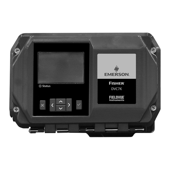
Quick Start Guide DVC7K-H Digital Valve Controller D104766X012 May 2024 Section 3: Installation 3.1 Housing Variations The DVC7K digital valve controller has a variety of different housing options. The instrument comes with a Local User Interface (LUI), as shown in Figure 1. Figure 1. -
Page 6: Valve/Actuator Mounting
DVC7K-H Digital Valve Controller Quick Start Guide May 2024 D104766X012 Table 1. Electrical and Pneumatic Configurations Electrical Conduit Entry Size Pneumatic Port Size Imperial 1/2 NPT 1/4 NPT Metric G1/4 Metric/Imperial 1/4 NPT Figure 2. Electrical and Pneumatic Configuration LEFT ELECTRICAL PNEUMATIC CONDUIT ENTRY CONDUIT... - Page 7 Quick Start Guide DVC7K-H Digital Valve Controller D104766X012 May 2024 NOTICE The magnet assembly material has been specifically chosen to provide a long‐term stable magnetic field. However, as with any magnet, care must be taken when handling the magnet assembly. Another high powered magnet placed in close proximity (less than 25 mm) can cause permanent damage.
-
Page 8: Sliding-Stem Linear Actuators
DVC7K-H Digital Valve Controller Quick Start Guide May 2024 D104766X012 3.3 Sliding‐Stem Linear Actuators Bracket Mounted Fisher 667 and 657 1. Isolate the control valve from the process line pressure and release pressure from both sides of the valve body. Shut off all pressure lines to the actuator, releasing all pressure from the actuator. - Page 9 Quick Start Guide DVC7K-H Digital Valve Controller D104766X012 May 2024 4. Using the alignment template (supplied with the mounting kit), position the magnet assembly inside the retaining slot. 5. Align the magnet assembly as follows: • For air‐to‐open actuators (e.g. Fisher 667) vertically align the magnet assembly so that the center line of the alignment template is lined up as close as possible with the upper extreme of the valid travel range on the magnet assembly.
- Page 10 DVC7K-H Digital Valve Controller Quick Start Guide May 2024 D104766X012 Figure 5. Air‐to‐Close Magnet Assembly Alignment ALIGNMENT TEMPLATE RETAINING SLOT INDEX MARK W9719 6. Tighten the fasteners and remove the alignment template. NOTE Use a flat end hex key to tighten the magnet assembly fasteners to a torque of 2.37 N•m / 21 lbf•in for 4 mm screws and 5.08 N•m / 45 lbf•in for 5 mm screws.
- Page 11 Quick Start Guide DVC7K-H Digital Valve Controller D104766X012 May 2024 Actuators over 210 mm / 8.25 in. Travel 1. Isolate the control valve from the process line pressure and release pressure from both sides of the valve body. Shut off all pressure lines to the pneumatic actuator, releasing all pressure from the actuator.
- Page 12 DVC7K-H Digital Valve Controller Quick Start Guide May 2024 D104766X012 Figure 7. Roller Arm Variation used for Sliding‐Stem (Linear) Actuators over 210 mm / 8.25 in. Travel CAM/ROLLER POSITION MARK ROLLER ARM ROLLER ACTUATOR IS FULLY EXTENDED E1229 E1543 Integral Mounted Fisher Actuators 1.
- Page 13 Quick Start Guide DVC7K-H Digital Valve Controller D104766X012 May 2024 WARNING Do not install a magnet assembly that is shorter than the physical travel of the actuator. Loss of control will result from the magnet assembly moving outside the range of the index mark in the feedback slot of the DVC7K housing and may result in personal injury or property damage.
- Page 14 DVC7K-H Digital Valve Controller Quick Start Guide May 2024 D104766X012 1. Tighten the fasteners and remove the alignment template. NOTE Use a flat end hex key to tighten the magnet assembly fasteners to a torque of 2.37 N•m / 21 lbf•in for 4 mm screws and 5.08 N•m / 45 lbf•in for 5 mm screws. For added security, especially in vibrating services, blue (medium) threadlocker may be used on the fasteners.
- Page 15 Quick Start Guide DVC7K-H Digital Valve Controller D104766X012 May 2024 5. Check for clearance between the magnet assembly and the DVC7K feedback slot. 6. If not already installed, install a vent in the port on the upper diaphragm casing. 7. Proceed to Section 4, Connect the Pneumatic Tubing on page 19. NOTE Refer to the 667 Diaphragm Actuator Sizes 30/30i to 76/76i and 87 instruction manual (D100310X012) for 667 product information.
- Page 16 DVC7K-H Digital Valve Controller Quick Start Guide May 2024 D104766X012 1. Tighten the fasteners and remove the alignment template. NOTE Use a flat end hex key to tighten the magnet assembly fasteners to a torque of 2.37 N•m / 21 lbf•in for 4 mm screws and 5.08 N•m / 45 lbf•in for 5 mm screws. For added security, especially in vibrating services, blue (medium) threadlocker may be used on the fasteners.
-
Page 17: Quarter-Turn Rotary Actuators
Quick Start Guide DVC7K-H Digital Valve Controller D104766X012 May 2024 3.4 Quarter-Turn Rotary Actuators Integral Mounted Fisher Actuators 1. Isolate the control valve from the process line pressure and release pressure from both sides of the valve body. Shut off all pressure lines to the pneumatic actuator, releasing all pressure from the actuator. - Page 18 DVC7K-H Digital Valve Controller Quick Start Guide May 2024 D104766X012 Figure 12. Rotary Actuator Mounting Variations ROLLER ROLLER ROLLER 2052 SIZE 2 AND 3 1051/1052 SIZE 40-70 1051 SIZE 33 2052 SIZE 1 SIZE 1061 SIZE 30-100 1052 SIZE 20-33 E1229 NOTE THE DIFFERENCE IN THE SHAPE AND LENGTH OF THE ROLLER ARM 3.
- Page 19 Quick Start Guide DVC7K-H Digital Valve Controller D104766X012 May 2024 Figure 13. Mounting on Quarter‐Turn Actuators M6 MOUNTING BOLTS (4) 2. Attach the magnet assembly to the actuator shaft. At mid‐travel, the flats on the magnet assembly should be approximately parallel to the channel on the back of the DVC7K housing, as shown in Figure 14.
- Page 20 DVC7K-H Digital Valve Controller Quick Start Guide May 2024 D104766X012 Figure 14. Magnet Assembly Orientation ORIENTATION AT ONE TRAVEL EXTREME MOUNTING BRACKET ORIENTATION AT MID‐TRAVEL (FLATS PARALLEL TO DVC7K HOUSING CHANNEL) MOUNTING BRACKET ORIENTATION AT THE OTHER TRAVEL EXTREME W8836‐1A W8836‐1B NOTES: 1.
-
Page 21: Section 4: Connect The Pneumatic Tubing
Quick Start Guide DVC7K-H Digital Valve Controller D104766X012 May 2024 Section 4: Connect the Pneumatic Tubing Figure 15. Integral Mounting of a Fisher 67CFR Regulator on a FIELDVUE DVC7K Digital Valve Controller OUTPUT A OUTPUT B 67CFR O‐RING SUPPLY CONNECTION SCREWS NOTE: 1. - Page 22 DVC7K-H Digital Valve Controller Quick Start Guide May 2024 D104766X012 Figure 16. DVC7K Digital Valve Controller Pneumatic Port Schematic SUPPLY OUTPUT B OUTPUT A PNEUMATIC ALTERNATE GAUGE BLOCK SUPPLY Figure 17. Pneumatic Gauge Block Mounting Screws SOCKET HEAD CAP SCREWS WITH O-RINGS (4) O-RINGS GAUGES (3)
- Page 23 Quick Start Guide DVC7K-H Digital Valve Controller D104766X012 May 2024 Figure 18. Pneumatic Gauge Block Pneumatic Port Schematic SUPPLY OUTPUT B OUTPUT A Figure 19. Top View: Pneumatic Port, Alternative Output A ALTERNATIVE OUTPUT A...
- Page 24 DVC7K-H Digital Valve Controller Quick Start Guide May 2024 D104766X012 Figure 20. Back View: Alternative Output A and Output B Ports ALTERNATIVE OUTPUT B ALTERNATIVE OUTPUT A Figure 21. Bottom View: Pneumatic Port, Alternative Output B ALTERNATIVE OUTPUT B...
- Page 25 Quick Start Guide DVC7K-H Digital Valve Controller D104766X012 May 2024 2. Connect the DVC7K pneumatic output to the actuator input using at least 10 mm / 3/8-in. diameter tubing. • When using a single-acting direct digital valve controller (relay A or C) on a single-acting actuator, connect OUTPUT A to the actuator pneumatic input.
- Page 26 (v/v) basis. Condensation in the air supply should be minimized. Check with an Emerson field office and industry instrument air quality standards for use with corrosive air or if you are unsure about the amount of air filtration or filter maintenance.
- Page 27 Quick Start Guide DVC7K-H Digital Valve Controller D104766X012 May 2024 Figure 22. Filter Mounting Locations HORIZONTAL MOUNTING VERTICAL MOUNTING DVC7K FILTER MOUNTING LOCATION GAUGE BLOCK FILTER MOUNTING LOCATIONS • When using an integral mounted 67CFR filter regulator, lubricate an O-ring and insert it in the recess around the SUPPLY connection on the digital valve controller.
- Page 28 DVC7K-H Digital Valve Controller Quick Start Guide May 2024 D104766X012 WARNING Personal injury or property damage can occur from cover failure due to overpressure. Ensure that the housing vent opening is open and free of debris to prevent pressure buildup under the cover. This unit vents the supply medium into the surrounding atmosphere.
- Page 29 Quick Start Guide DVC7K-H Digital Valve Controller D104766X012 May 2024 Figure 23. Vent Connections STANDARD VENT PIPE-AWAY BLOCK WARNING To avoid personal injury or property damage resulting from bursting or parts, do not exceed maximum supply pressure. Personal injury or property damage may result from fire or explosion if natural gas is used as the supply medium and appropriate preventive measures are not taken.
-
Page 30: Section 5: Connect The Electrical Wires
DVC7K-H Digital Valve Controller Quick Start Guide May 2024 D104766X012 Section 5: Connect the Electrical Wires WARNING Select wiring and/or cable glands that are rated for the environment of use (such as hazardous area, ingress protection and temperature). Failure to use properly rated wiring and/or cable glands can result in personal injury or property damage from fire or explosion. - Page 31 Quick Start Guide DVC7K-H Digital Valve Controller D104766X012 May 2024 WARNING Personal injury or property damage, caused by fire or explosion, can result from the discharge of static electricity. Connect a 14 AWG / 2.08 mm ground strap between the digital valve controller and earth ground when flammable or hazardous gases are present.
-
Page 32: I/O Options: Position Transmitter And Two Discrete Switches
HF340 HART filter instruction manual (D102796X012). To determine if your system requires a HART filter refer to the DVC7K instruction manual (D104767X012) or contact your Emerson sales office. 6. If your digital valve controller is explosion proof (ExD) screw the terminal cap back onto the terminal box until no gap remains and then tighten the lock screw (clockwise). - Page 33 Quick Start Guide DVC7K-H Digital Valve Controller D104766X012 May 2024 The position transmitter circuit derives its operating power from the control system input channel in the same manner as a 2-wire transmitter. Each discrete switch is a solid state circuit (1-amp maximum) which opens and closes based on a user configurable trip point.
-
Page 34: Smart Wireless Thum Adapter
DVC7K-H Digital Valve Controller Quick Start Guide May 2024 D104766X012 5.2 Smart Wireless THUM Adapter Refer to the Smart Wireless THUM Adapter quick installation guide (00825-0100-4075) for additional information. 1. Remove the DVC7K terminal box plug from the conduit entrance. 2. -
Page 35: Section 6: Local User Interface (Lui) Flow Chart
Quick Start Guide DVC7K-H Digital Valve Controller D104766X012 May 2024 Section 6: Local User Interface (LUI) Flow Chart 6.1 Overview STATUS, INPUT CURRENT (ONLY POINT TO POINT MODE), SETPOINT, TRAVEL, TRAVEL DEVIATION, SUPPLY PRESSURE, OVERVIEW PRIMARY VARIABLES OUTPUT A (ONLY SINGLE DIRECT OR DOUBLE ACTING), OUTPUT B (ONLY REVERSE OR DOUBLE ACTING) 1.2.3 1.2.2... -
Page 36: Configure
DVC7K-H Digital Valve Controller Quick Start Guide May 2024 D104766X012 6.2 Configure CONFIGURE GUIDED SETUP INSTRUMENT MODE SECURITY HART TAG WRITE PROTECTION [ON AUTOMATIC, MANUAL 8 CHARACTER TEXT FIELD WITH LUI VALIDATION, ON WITHOUT LUI VALIDATION, PROTECTION OFF] 2.5.2 2.5.3 2.5.1 UNITS TEMPERATURE... -
Page 37: Service Tools
Quick Start Guide DVC7K-H Digital Valve Controller D104766X012 May 2024 6.3 Service Tools SERVICE TOOLS ACTIVE ALERTS 3.2.1 3.2.2 3.2.3 VARIABLES STATUS TRAVEL PRESSURE SUPPLY PRESSURE, OUTPUT A STATUS, WRITE PROTECT, INPUT CURRENT (ONLY POINT (ONLY SINGLE DIRECT OR DOUBLE RUNTIME, POWER UPS, TO POINT MODE), SETPOINT, ACTING), OUTPUT B (ONLY REVERSE... - Page 38 DVC7K-H Digital Valve Controller Quick Start Guide May 2024 D104766X012 Status Information The first (home) screen on the LUI that is displayed after applying power to the instrument contains basic status information. On an instrument that is calibrated and operating properly, the home screen, shown in Figure 28, displays the following information: 1.
- Page 39 Quick Start Guide DVC7K-H Digital Valve Controller D104766X012 May 2024 Guided Setup Local User Interface 2. Configure > 2.1 Guided Setup WARNING • Select wiring and/or cable glands that are rated for the environment of use (such as hazardous area, ingress protection and temperature). Failure to use properly rated wiring and/or cable glands can result in personal injury or property damage from fire or explosion.
- Page 40 DVC7K-H Digital Valve Controller Quick Start Guide May 2024 D104766X012 When the DVC7K digital valve controller is ordered as part of a control valve assembly, the factory mounts the digital valve controller and sets up the instrument as specified on the order.
- Page 41 Quick Start Guide DVC7K-H Digital Valve Controller D104766X012 May 2024 NOTE A label affixed to the relay itself will specify the relay type. Relay B (for single-acting reverse applications) and Relay C (for single-acting direct applications) are calibrated at the factory and requires no further adjustment. Rotate the adjustment disc, shown in Figure 29, until the output pressure displayed is between 50 and 70% of supply pressure.
-
Page 42: Configuration Using An Emerson Handheld Communicator
If the Instrument Mode was changed to Manual to perform Guided Setup, you will be prompted to return the Instrument Mode to Automatic. If Write Protection was disabled, you will be prompted to re-enable the Write Protection. 7.2 Configuration Using an Emerson Handheld Communicator Handheld Communicator Device Setting >... - Page 43 Quick Start Guide DVC7K-H Digital Valve Controller D104766X012 May 2024 2. Apply pneumatic supply pressure to the digital valve controller and adjust the supply pressure regulator according to the actuator requirements and limitations. 3. Apply electrical power to the digital valve controller. 4.
- Page 44 Responsibility for proper selection, use, and maintenance of any product remains solely with the purchaser and end user. Fisher and FIELDVUE are marks owned by one of the companies in the Emerson business unit of Emerson Electric Co. Emerson and the Emerson logo are trademarks and service marks of Emerson Electric Co.
Need help?
Do you have a question about the Fisher FIELDVUE DVC7K-H and is the answer not in the manual?
Questions and answers