Table of Contents
Advertisement
Quick Links
P.O. BOX 557 204 INDUSTRIAL PARK DRIVE
LAKEFIELD, MINNESOTA USA 56150-0577
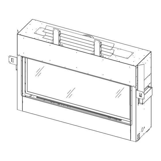
Nordik 60 TL
Model #NDK-60-TL
Direct Vent Gas Fireplace
Evolution of Fire
with the EVO Elevated Burner
English and French installation manuals are available
through your local dealer or website. Visit our website
www.kozyheat.com.
Les manuels d'installation en français et en anglais sont
disponibles chez votre détaillant local. Visitez
www.kozyheat.com.
⚠ WARNING:
FIRE OR EXPLOSION HAZARD
Failure to follow safety warnings exactly
could result in serious injury, death, or
property damage.
-
Do not store or use gasoline or other
flammable vapors and liquids in the
vicinity of this or any other appliance.
-
WHAT TO DO IF YOU SMELL GAS
•
Do not try to light any appliance.
Do not touch any electrical switch; do not
•
use any phone in your building.
•
Leave the building immediately.
Immediately call your gas supplier from a
•
neighbor's phone. Follow the gas
supplier's Instructions.
If you cannot reach your gas supplier, call
•
the fire department.
-
Installation and service must be
performed by a qualified installer, service
agency or the gas supplier
Hussong Mfg. Co, Inc.
NDK-60-TL - PFS Report No. 24-254
INSTALLATION AND
OPERATION MANUAL
This appliance may be installed in an aftermarket, permanently
located, manufactured home (USA only) or mobile home, where
not prohibited by local codes.
This appliance is only for use with the type of gas indicated on the
rating plate. A conversion kit is supplied with the appliance.
INSTALLER: Leave this manual with the appliance.
CONSUMER: Retain this manual for future reference.
1
Starting Serial Number: 24 N60TL00001 26
Rev. 1 - April 2024
Advertisement
Table of Contents

Related Manuals for kozy heat Nordik 60 TL


Summary of Contents for kozy heat Nordik 60 TL
- Page 1 INSTALLATION AND OPERATION MANUAL P.O. BOX 557 204 INDUSTRIAL PARK DRIVE LAKEFIELD, MINNESOTA USA 56150-0577 Nordik 60 TL Model #NDK-60-TL Direct Vent Gas Fireplace Evolution of Fire with the EVO Elevated Burner English and French installation manuals are available through your local dealer or website. Visit our website www.kozyheat.com.
- Page 2 Hussong Mfg. Co, Inc. Rev. 1 - April 2024 NDK-60-TL - PFS Report No. 24-254 Starting Serial Number: 24 N60TL00001 26...
-
Page 3: Homeowner Reference Information
CONGRATULATIONS! Hussong Manufacturing welcomes you as a new owner of a Kozy Heat gas fireplace. Kozy Heat products are designed with superior components and materials, assembled with care by trained crafts- men who take pride in their work. To ensure you receive a quality product, the burner and valve as- sembly are 100 percent test-fired, and the complete fireplace is thoroughly inspected before packag- ing. - Page 4 Hussong Mfg. Co, Inc. Rev. 1 - April 2024 NDK-60-TL - PFS Report No. 24-254 Starting Serial Number: 24 N60TL00001 26...
-
Page 5: Table Of Contents
TABLE OF CONTENTS HOMEOWNER REFERENCE INFORMATION ....3 8.0 Venting ................. 39 TABLE OF CONTENTS ............. 5 8.1 Approved Vent Systems ..........39 1.0 Introduction ............7 8.2 Venting Requirements ..........40 1.1 Appliance Certification ......... 7 8.3 Vent Restriction............40 1.2 California Proposition 65 Warning ....... - Page 6 Hussong Mfg. Co, Inc. Rev. 1 - April 2024 NDK-60-TL - PFS Report No. 24-254 Starting Serial Number: 24 N60TL00001 26...
-
Page 7: Introduction
1.0 Introduction 1.1 Appliance Certification 1.3.2 Approved Carbon Monoxide Detectors Laboratory: PFS in Cottage Grove, Wisconsin Each carbon monoxide detector as required in accordance with the above provisions shall comply with NFPA 720 and be ANSI/UL Standards: 2034 listed and IAS certified. •... -
Page 8: Specifications
2.0 Specifications 2.1 Heating Specifications Natural Gas Propane Maximum Input Rating 51,000 Btu/h 51,000 Btu/h (14.95 kW) (14.95 kW) Orifice Size (DMS) Left: #48 Left: #1.10mm Center: #48 Center: #1.10mm Right: #48 Right: #1.10mm Bottom: #54 Bottom: #65 Minimum Input Rating 34,000 Btu/h 40,000 Btu/h (9.96 kW) -
Page 9: Electrical Specifications
2.1.2 Altitude Adjustment This appliance may be installed at higher altitudes. Please refer to National Fuel Gas Code ANSI Z223.1/NFPA 54, CSA-B149.1 Natural Gas and Propane Installation Code, local authorities, or codes having jurisdiction in your area regarding derate guidelines. 2.1.2.1 US Installations Refer to the American Gas Association guidelines for the gas designed appliances derating method. -
Page 10: Safety Barrier Information
2.4 Safety Barrier Information WARNING: A barrier designed to reduce the risk of burns from the hot viewing glass is provided with this appliance and shall be installed for the protection of children and other at-risk individuals. If the barrier becomes damaged, the barrier shall be replaced with Hussong Mfg.’s barriers for this appliance. Please refer to Section 5.3 Safety Barrier Installation for installation information. -
Page 11: Framing
3.0 Framing • 3.1 Appliance Placement Considerations Heat Transfer Kit(s) allows you to transfer heat to a specific area inside your home (interior) or directly outside (exterior). Read all documentation for your specific installation and This appliance can have (2) heat transfer kits installed at the design options prior to appliance installation. -
Page 12: Setting The Appliance
3.4 Setting the Appliance This section outlines general information on setting the appliance in the framed opening and starting the installation process. Decide on your appliance installation option mentioned in Section 3.2 before setting the appliance. Your framing requirements, clearance to combustibles, and vent configuration will depend upon this decision. IMPORTANT: If you are using a Kozy Zone Kit and/or Heat Transfer Kit option refer to Section 4.0 for additional preparation steps that must be completed before setting the appliance in the framed opening. -
Page 13: Stand-Off Assembly And Installation
3.5 Stand-Off Assembly and Installation WARNING: The top stand-offs provide the 7-7/8” (200mm) minimum clearance to the header. Use only non-combustible material in this area for the entire width of the fireplace. DO NOT use wood, sheetrock, et cetera, in this zone. Top stand-off brackets must be formed and attached prior to positioning fireplace into framed opening. -
Page 14: Nailing Flange Assembly And Installation
3.6 Nailing Flange Assembly and Installation 3. Secure the nailing flanges to the fireplace with screws (provided) through the slots in nailing flanges. CAUTION: Never permanently remove these assemblies 4. Bend perforation on nailing flange until parallel with from the fireplace. They must be secured regardless of fireplace face. -
Page 15: Clearance To Combustibles
3.7 Clearances to Combustibles • See Table 3.1 below for minimum clearances for the standard installation option. • See Figure 3.3 on the following pages for typical standard installation options. • Unless otherwise noted all clearances / images in this manual are based off of nominal 2” x 4” framing being used. IMPORTANT: Clearances may change when utilizing the Komfort Zone Kit (Part# KZK-062). - Page 16 Nominal 2”x4” framing used in interior enclosure framing Figure 3.3 - Typical Appliance Installation Hussong Mfg. Co, Inc. Rev. 1 - April 2024 NDK-60-TL - PFS Report No. 24-254 Starting Serial Number: 24 N60TL00001 26...
-
Page 17: Wall Enclosure Rough Framing
3.8 Wall Enclosure Rough Framing • Framing dimensions should allow for wall covering Note: Unless otherwise noted all clearances / images in this thickness and fireplace facing materials. manual are based off of nominal 2” x 4” framing being used. •... -
Page 18: Vent Termination Framing
3.9 Vent Termination Framing The following information applies to all standard, and Komfort Zone Kit design options. If using Kozy Power Vent #KPV, please reference the manual included with the kit. 3.9.1 Vent Termination Location Nominal 2”x4” framing used in interior •... - Page 19 3.9.3 Vent Heat Shield Installation • Vent heat shields must be installed. • When the vent pipe terminates at the ceiling of the fireplace enclosure you only use the front vertical vent heat shield as shown in Figure 3.6. • When the vent pipe terminates at the wall at the minimum vent run use the front vertical and top horizontal vent heat shield as shown in Figure 3.6.
- Page 20 3.9.5 Wall Pass Through Framing Instructions Follow FIGURE 3.7 below for minimum rough-in dimensions. Measure from floor level of the fireplace to the center of where the vent pipe will penetrate the wall. The dimension in FIGURE 3.7 is used with a Simpson DuraVent elbow. Cut and frame an opening in the wall to allow the vent system to run level through the wall pass-through.
-
Page 21: Outdoor Covered Fireplace Installation
3.10.2 Requirements 3.10 Outdoor Covered Fireplace Installation • The continuous insulated building envelope and A outdoor covered fireplace installation allows a fireplace weatherproof membrane are not to be interrupted by to be installed in an outdoor covered area, where the fireplace installation. - Page 22 Figure 3.9 - Outdoor Covered Installation Hussong Mfg. Co, Inc. Rev. 1 - April 2024 NDK-60-TL - PFS Report No. 24-254 Starting Serial Number: 24 N60TL00001 26...
-
Page 23: Heat Management
4.0 Heat Management The Komfort Zone Kit (KZK) offers the option to redistribute radiant heat through plenum(s). This option allows for combustible facing materials above the fireplace, heat reduction for a TV above the fireplace, and lower mantel clearances. • If installing a Komfort Zone Kit (#KZK-062), the clearance to combustible requirements may be different than the standard dimensions listed in this section. - Page 24 Figure 4.2 - KZK Collar Installation Figure 4.3 - Convection Baffle Removal Hussong Mfg. Co, Inc. Rev. 1 - April 2024 NDK-60-TL - PFS Report No. 24-254 Starting Serial Number: 24 N60TL00001 26...
-
Page 25: Appliance Preparation For An Interior Or Exterior Heat Transfer Kit
4.2 Appliance Preparation for an Interior or Exterior Heat Transfer Kit Preparation Instructions Remove the (4) sheet metal screws that secure the HTK cover plate on the side of the appliance. Save these (4) sheet metal screws for later use. Install the HTK air chute (Part # HTK-NTL) on the appliance as shown in Figure 4.4. - Page 26 Figure 4.5 - Damper Installation Resting Position Figure 4.6 - HTK-INT Damper Removal Hussong Mfg. Co, Inc. Rev. 1 - April 2024 NDK-60-TL - PFS Report No. 24-254 Starting Serial Number: 24 N60TL00001 26...
-
Page 27: Facing And Finishing
Requirements Disclaimer: Kozy Heat does not guarantee any materials used • around the fireplace. Kozy Heat disclaims any and all liability Noncombustible Mantel Projections: As referenced in for any damage to finishing materials including warping, FIGURE 5.3, the 8” noncombustible mantel projection discoloring, cracking, peeling or flaking. - Page 28 Refer to the manufacturer and supplier of your finishing material for use in high heat applications like around a fireplace. Ensure the material can be exposed to temperatures greater than 160°F. Kozy Heat does not assume any liability for discoloring, cracking, or other heat related damage.
- Page 29 Figure 5.2 shows a 6” combustible mantel projection starting 12” up from the top finishing edge of the fireplace. The dimensions shown are allowed in standard installation scenario. Mantel projections can increase 1" (25mm) of depth for every 1" (25mm) of height starting at the 6" (152mm) mantel. A combustible hearth is allowed with unlimited projection starting flush at the bottom finishing edge of the fireplace.
- Page 30 Figure 5.3 shows a 8” (203mm) non-combustible mantel projection flush with the top finishing edge of the fireplace. The dimensions shown are allowed in the standard installation scenario. Mantel projections can increase 1" (25mm) of depth for every 1" (25mm) of height starting at the 8" (203mm) mantel. A combustible hearth is allowed with unlimited projection starting flush at the bottom finishing edge of the fireplace.
- Page 31 Figure 5.4 shows a maximum of a 8” non-combustible surround is allowed 0” (0mm) from the fireplace finishing edge. The horizontal and vertical dimension of the surround is unlimited. Figure 5.4 shows the allowance of an unlimited hearth extension Figure 5.4 - Non-Combustible Surround Projection Hussong Mfg.
- Page 32 Figure 5.5 shows a combustible sidewall flush with the side finishing edge of the fireplace. The combustible sidewall is allowed to be unlimited. If you are using the optional NK60TL-RS Rectangle Surround (Section 5.2) provide the necessary clearance to sidewall. Figure 5.5 - Combustible Sidewall Projection Hussong Mfg.
- Page 33 Figure 5.6 - Non-Combustible Finishing Material Requirements Hussong Mfg. Co, Inc. Rev. 1 - April 2024 NDK-60-TL - PFS Report No. 24-254 Starting Serial Number: 24 N60TL00001 26...
-
Page 34: Rectangle Surround Installation
5.2 Rectangle Surround Installation The rectangle surround (#NK60TL-RS) is an optional accessory for this fireplace. The purpose of this surround is to cover the edge of finishing material where it meets the finishing edge along all 4 sides of the fireplace opening. The rectangle surround accommodates up to 1-5/8”... -
Page 35: Safety Barrier Installations
5.3 Safety Barrier Installation Note: A barrier designed to reduce the risk of burns from the hot viewing glass is provided with this appliance and shall be installed for the protection of children and other at-risk individuals • If the barrier becomes damaged, the barrier shall be replaced with the manufacturer’s barrier for this appliance •... -
Page 36: Gas Line Connection
6.0 Gas Line Connection 6.1 Gas Conversion Note: Stepper Motor sold separately to complete gas conversion ATTENTION: The conversion shall be carried out in accordance with the requirements of the provincial authorities having jurisdiction and in accordance with the requirements of the ANSI Z223.1 installation code. This fireplace is manufactured for use with natural gas. -
Page 37: Termination Locations
7.0 Termination Locations 7.1 Vertical Vent Cap Termination WARNING: This gas appliance must not be connected to a chimney flue serving a separate solid-fuel burning appliance. Note: Natural Draft Applications only. • Refer to Figure 7.1 below for vertical vent terminations clearances. •... -
Page 38: Minimum Termination Clearances
Please refer to vent manufacturer for information regarding vinyl siding protectors. Kozy Heat assumes no responsibility or liability for damages caused to vinyl or PVC siding in this type of installation. Figure 7.3 - Termination Clearances... -
Page 39: Venting
Refer to the vent pipe manufacturer’s installation manual for This appliance is approved for use with Kozy Heat Power Vent more information. System #KPV (sold separately). Power Vent configurations and requirements are located in the #KPV manual. -
Page 40: Venting Requirements
8.2 Venting Requirements 8.3 Vent Restriction • NOTE: Consult the local and national installation codes to Burner flame appearance and characteristics are assure adequate combustion and ventilation air is affected by altitude, fuel quality, venting configuration, available. Venting requirements apply to both natural gas and other factors. -
Page 41: Natural Draft Co-Axial Vent Pipe Installations
8.5 Natural Draft Co-Axial Pipe Installations (ii) Minimum / Maximum Vertical Terminations with 8.5.1 Vertical Terminations Reducer*: 4” x 6-5/8” reducer + 3’ (914mm) minimum vertical Note: Natural Gas and Propane Installations length / 50’ (15.24m) maximum vertical length + Minimum / Maximum Vertical Terminations: termination cap 3’... - Page 42 8.5.2 Horizontal Terminations (iii) Minimum 36” Vertical Vent Pipe / Minimum Horizontal: Note: Natural Gas and Propane Installations 36” (914mm) vertical vent pipe + 90° horizontal elbow + termination cap IMPORTANT: Horizontal vent sections require 1/4” (6mm) of rise for every 12” (305mm) of travel. (iii) Minimum 36”...
- Page 43 Figure 8.5 - Horizontal 5”x 8” Vent Pipe Hussong Mfg. Co, Inc. Rev. 1 - April 2024 NDK-60-TL - PFS Report No. 24-254 Starting Serial Number: 24 N60TL00001 26...
- Page 44 8.5.3 Combination Venting • 25’ (7.62m) maximum vertical rise + 25’ (7.62m) maxi- mum horizontal run = 50’ (15.2m) of total length Note: Natural Gas and Propane Installations • Maximum of (5) 90° elbows. For each additional 90° el- Vent termination must be within the shaded area in bow used after the first elbow, 3’...
-
Page 45: Class A Chimney / Masonry Chimney Conversion
8.6 Class A Chimney / Masonry Chimney Conversion This appliance is approved to be adapted for Class A/Masonry Chimney conversion with kits utilizing a 4” (102mm) flexible exhaust by any vent manufacturers listed in section 8.1, APPROVED VENT SYSTEMS. Before conversion, have the existing installation inspected by a qualified chimney sweep or professional installer. The existing chimney system must be in serviceable condition, and functionally sound. -
Page 46: Fireplace Setup
9.0 Fireplace Setup 9.1 Glass Frame Assembly WARNING: Do not operate this fireplace with the glass removed, cracked, or broken. Replacement of the glass assembly, should be done by a licensed or qualified service person. 9.1.1 Remove Glass Frame Assembly WARNING: Do not remove the glass assembly when hot. -
Page 47: Component Access Tray
9.2 Component Access Tray To access the valve and control module housing, the component access tray will need to be removed. It must be reinstalled after servicing. Remove safety barrier. Lift up and remove the component access tray to gain access below the fireplace. See Figure 9.2. Figure 9.2 - Component Access Tray Removal 9.3 Light Kits ATTENTION: If converting to propane do so now before installing any light kit components. - Page 48 Figure 9.3 - Log Rack / Ember Media Tray Removal Figure 9.4 - Left, Center, and Right Burner Removal Hussong Mfg. Co, Inc. Rev. 1 - April 2024 NDK-60-TL - PFS Report No. 24-254 Starting Serial Number: 24 N60TL00001 26...
-
Page 49: Nk60Tl-500 Log Set Installation
9.3.2 Install Light Bulbs - Back Bottom Light Kit • Halogen bulbs are preinstalled from the factory. See instructions below for bulb replacement. • Note: The instructions in Section 9.3.2 are a continuation of Section 9.3.1. Remove and retain the (6) screws for the left, center, and right burners. Remove burners. See Figure 9.4. Remove and retain (2) screws from the back ember bed media tray. -
Page 50: Control Board Removal And Installation
9.5 Control Board Removal and Installation WARNING: If burner and/or pilot have been burning, use appropriate protection to avoid burns or damage to personal property before removing any components. DO NOT OPERATE THIS APPLIANCE WITHOUT THE SEALING GASKET (LOCATED UNDER THE CONTROL BOARD) IN PLACE. - Page 51 Figure 9.9 - Step 4 Figure 9.10 - Step 5 Figure 9.11 - Step 6 Hussong Mfg. Co, Inc. Rev. 1 - April 2024 NDK-60-TL - PFS Report No. 24-254 Starting Serial Number: 24 N60TL00001 26...
-
Page 52: Electrical Information
10.0 Electrical Information WARNING: Do not use this fireplace if any part has been under 10.2 Wiring Requirements water. Immediately call a qualified service technician to inspect this appliance and to replace any part of the control system and • The system requires 120 VAC of electricity and/or any gas control which has been under water. - Page 53 • Figure 10.2 shows a close up of the wiring diagram. This figure shows the main power cord, optional fan kit, top light kit, ember bed light kit, and pilot assembly. Figure 10.2 - Electrical Diagram - Close up #1 Hussong Mfg.
- Page 54 • Figure 10.3 shows a close up of the wiring diagram. This figure shows the pilot assembly, on / off rocker switch, battery back -up, valve, and SW1 Remote Learn Button. Figure 10.3 - Electrical Diagram - Close up #2 Hussong Mfg.
-
Page 55: Operating Instructions
11.0 Operating Instructions Hussong Mfg. Co, Inc. Rev. 1 - April 2024 NDK-60-TL - PFS Report No. 24-254 Starting Serial Number: 24 N60TL00001 26... -
Page 56: Setup Proflame
11.1 Setup Proflame 2 IFC Module 11.3 Reset the System for Manual Operation Set the main ON/OFF rocker switch in the OFF 1. Access the toggle switch and remote learn button on the position. left side of the unit by removing the safety barrier screen by lifting up and out of its slots. -
Page 57: Control System 7 Day Timeout
11.7.1.2 Remote Control ON/OFF Key 11.6 Control System 7 Day Timeout 1. Press the remote control ON/OFF key to turn the • If you have your Proflame 2 system set to CPI system OFF. (continuous pilot ignition) with 7 consecutive days without ignition of the main burner, the pilot will turn 2. -
Page 58: Remote Control Operation
11.9 Remote Control Operation Figure 11.1 - Remote control overview 11.9.1 Temperature Display 11.9.2 Key Lock 1. With the system in the OFF position, simultaneously press This function locks the keys to avoid unsupervised the thermostat key and the mode key to change degrees operation. - Page 59 11.9.3 Pilot Ignition Selection (IPI/CPI) 11.9.6 Remote Control Flame Adjustment This control system has (6) flame levels. If the smart This system has the option of a continuous (standing) thermostat operation is activated, then the manual pilot. This features allows the system to change from a adjustment of the flame height will be disabled.
- Page 60 11.9.6.1 Deactivate Flame Modulation 11.9.7.2 Smart Thermostat Verify all (3) AAA batteries are installed in the remote The smart thermostat function will adjust the flame height control battery bay. based on the set temperature and the actual room temperature. The smart thermostat function automatically Remove (1) AAA battery.
- Page 61 11.9.8 Fan Speed Control 11.9.9 Top Accent Light Kit Fan speed can be adjusted through (6) speeds. To activate The top light intensity can be adjusted through (6) levels. this function, 1. Press the mode key to index to the light icon. ...
- Page 62 11.9.10 Activate Ember Bed Light Kit (auxiliary) 11.9.10.1 Adjust Ember Bed Light Kit Intensity (after turning “ON”) The auxiliary function controls ON/OFF function the ember bed light kit. To activate this function, The ember bed light kit intensity can be adjusted by using the ember bed light kit modulator knob located underneath the firebox 1.
- Page 63 11.9.10.2 Deactivation AUX (Ember Bed Light Kit) 1. Verify all (3) AAA batteries are installed in the remote control battery bay. 2. Remove (1) AAA battery. 3. Press and hold the on/off key and the mode key at the same time. 4.
-
Page 64: Pressure Testing And Burner Adjustments
12.0 Pressure Testing and Burner Adjustments 12.1 Pressure Testing Table 12.1 Inlet Pressures NOTE: The appliance and its appliance main gas valve Fuel Natural Gas Propane must be disconnected from the gas supply piping system during any pressure testing of the system at test Gas Supply Min - Max Min - Max... -
Page 65: Flame Appearance Adjustment
12.2 Flame Appearance Adjustment WARNING: To avoid property damage or personal injury, allow the fireplace ample time to cool before making any adjustments. Burner flame appearance and characteristics are affected by altitude, fuel quality, venting configuration, and other factors. After installation, this appliance may need additional adjustments to achieve optimum flame appearance and visual aesthetics. - Page 66 Figure 12.2 - Burner Venturis Figure 12.3 - Flame Appearance and Characteristics Hussong Mfg. Co, Inc. Rev. 1 - April 2024 NDK-60-TL - PFS Report No. 24-254 Starting Serial Number: 24 N60TL00001 26...
- Page 67 12.2.3 Vent Restriction (after installation) Table 12.5 Restrictor Plate Adjustment Guidelines WARNING: To avoid property damage or personal injury, Flame Appearance Draft Problem Solution allow the fireplace ample time to cool before making any adjustments. WARNING: Improper vent installation may cause the Short, flickering Excessive draft and/or Add restrictor plate...
-
Page 68: Troubleshooting
13.0 Troubleshooting ATTENTION: Troubleshooting must be performed by a qualified technician. Before proceeding with the steps in the following troubleshooting guide, • • Verify proper 120VAC power supply to the control Verify inlet pressure meets the recommended inlet pressure. If module. - Page 69 Issue Cause Solution Burner flame will not light ON/OFF rocker switch in OFF position Switch rocker switch to ON position. Gas supply turned off Check for multiple shut-offs in the supply line. Verify gas supply is turned on. Low gas supply Consult with plumber or gas supplier.
- Page 70 Issue Cause Solution Flame burns blue and lifts off Improper venturi setting The venturi air shutter may need to be burner close slightly to allow less air into the gas mix. Refer to section 12.2.1, BURNER VENTURIS. Incorrect vent cap installation Adjust if necessary.
-
Page 71: Maintenance
14.0 Maintenance ATTENTION: Installation and repair should only done by a qualified service person. The appliance should be inspected before use and at least annually by a professional service person. More frequent cleaning might be required due to excessive lint from carpeting, bedding material, et cetera. -
Page 72: Burner And Pilot System
14.5 Burner and Pilot System The burner assembly may be removed for easier access to the control compartment. See Section 9.5 Control Board Removal and Installation for instructions. See Section 12.2 Flame Appearance Adjustment for information on adjusting burner appearance. Verify gas supply is turned on and filled. - Page 73 Figure 14.2 Correct pilot flame appearance Figure 14.3 - Correct burner flame appearance Hussong Mfg. Co, Inc. Rev. 1 - April 2024 NDK-60-TL - PFS Report No. 24-254 Starting Serial Number: 24 N60TL00001 26...
-
Page 74: Replacement Parts List
15.0 Replacement Parts List Replacement parts are available through your local dealer. Contact your local dealer for availability and pricing. The following warning is for replacement parts for this appliance. ⚠ WARNING: This product can expose you to chemicals including Lead, which is [are] known to the State of California to cause cancer, birth defects P.O. - Page 75 Glass and Glass Parts Light Kits Glass with Gasket - 61-3/4” x 22-1/8” 701-066T 20W Halogen Bulb 600-676 1 1/8” Glass Gasket with Adhesive 900-007 Light Kit - Ember Bed NK60TL-LKT Replacement Valance NK60TL-005 Light Kit - Top 600-TLK Glass Latch Tool JOR-GLT 1.5lb.
-
Page 76: Limited Lifetime Warranty
Hussong Manufacturing Company, Inc. (Hussong Mfg.) All parts and material except the items listed in the 30 day warrants this Kozy Heat gas appliance from the date of warranty and any exclusions or limitations that may apply purchase to the original purchaser, that it is free of defects in materials and workmanship at the time of manufacture. - Page 77 Limited Lifetime Warranty EXCLUSIONS AND LIMITATIONS (continued) 10. It is expressly agreed and understood that this warranty is Hussong Mfg.’s sole obligation and purchaser’s exclusive remedy for defective fireplace equipment. Hussong Mfg. is free of liability for any damages caused by this appliance, as well as inconvenience expenses and materials.
- Page 78 Hussong Mfg. Co, Inc. Rev. 1 - April 2024 NDK-60-TL - PFS Report No. 24-254 Starting Serial Number: 24 N60TL00001 26...
Need help?
Do you have a question about the Nordik 60 TL and is the answer not in the manual?
Questions and answers