
Related Manuals for THORLABS PM60A


Summary of Contents for THORLABS PM60A
- Page 1 PM60A, PM60C, PM60CH PM61A, PM61C, PM61CH Field Service Fiber Optic Power Meter User Guide...
-
Page 2: Table Of Contents
Field Service Fiber Optic Power Meter Table of Contents Chapter 1 Introduction ....................... 1 1.4.1 Specifications ..............................1 1.4.2 Main Features ..............................3 1.4.3 Mechanical Drawings ............................4 Chapter 2 Safety ......................... 9 Chapter 3 Installation ....................... 10 Chapter 4 Operation ......................... - Page 3 4.10.1 USB 2.0 Interface ............................... 29 4.10.2 Bluetooth Interface (PM61 Series Only) ......................30 Chapter 5 Maintenance and Cleaning ..................30 Chapter 6 Troubleshooting and Repair ..................34 Chapter 7 Disposal ........................35 Chapter 8 Thorlabs Worldwide Contacts ................... 36...
-
Page 4: Chapter 1 Introduction
Each unit comes with a 2.5 mm ferrule adapter to connect to the most commonly used fiber tips, such as FC or SC. Thorlabs also offers additional adapters for different fiber connectors. The PM61 series has additional features like the built-in visual fault locator that emits light in three different modes to trace fibers and identify breaks. - Page 5 Field Service Fiber Optic Power Meter Chapter 1 Introduction Item # PM60A, PM61A PM60C, PM61C PM60CH, PM61CH Sensor Specifications -65 dBm to 16 dBm -70 dBm to 13 dBm -55 dBm to 23 dBm Optical Power Range (300 pW to 40 mW)
-
Page 6: Main Features
Field Service Fiber Optic Power Meter Chapter 1 Introduction 1.4.2 Main Features Features PM60 Series PM61 Series 2.8” IPS Color Display Capacitive Touchscreen Physical Control Buttons Rubber Protection and Foldable Stand ... -
Page 7: Mechanical Drawings
Field Service Fiber Optic Power Meter Chapter 1 Introduction 1.4.3 Mechanical Drawings Figure 1 PM60 Series Mechanical Drawing Page 4 MTN039852-D02... - Page 8 Field Service Fiber Optic Power Meter Chapter 1 Introduction Figure 2 PM61 Series Mechanical Drawing Rev. A, May 15, 2024 Page 5...
- Page 9 Field Service Fiber Optic Power Meter Chapter 1 Introduction Components Detector Port VFL (PM61 series only) Touchscreen Display Power (on/off) Button Menu Button Control Pad Eyelet for Hand Strap Figure 3 PM60 and PM61 Series Front Panel Charging LED USB 2.0 Type-C Connector Fold-out Stand Figure 4...
- Page 10 Connect the equipment into an outlet on a circuit different from that to which the receiver is connected. Users that change or modify the product described in this manual in a way not expressly approved by Thorlabs (party responsible for compliance) could void the user’s authority to operate the equipment.
- Page 11 Field Service Fiber Optic Power Meter Chapter 1 Introduction US / Canada Registration Number China Registration Number: and Labeling on the Device: 本设备包含型号核准代码(分别)为: CMIIT ID: 2021DJ2218的无线电发射模块。 Japanese Giteki Mark and Registration Number: Brazil Registration Number: 03882-16-05903 Korean KC Mark and Registration Number: “Este equipamento opera em caráter secundário, isto é, não tem direito a proteção contra interferência prejudicial, mesmo de estações do...
-
Page 12: Chapter 2 Safety
All statements regarding safety of operation and technical data in this instruction manual will only apply when the unit is operated correctly as it was designed for. Changes to this device cannot be made nor may components not supplied by Thorlabs be used without written consent from Thorlabs. -
Page 13: Chapter 3 Installation
FC/APC. To allow a steady connection of the fiber or for SMA or LC fibers, Thorlabs offers various adapters from the PM20 adapter series to replace the attached PM20-25 adapter. To remove an adapter, unscrew the installed adapter counterclockwise and replace it by the desired PM20 series adapter. -
Page 14: Chapter 4 Operation
Field Service Fiber Optic Power Meter Chapter 4 Operation First Measurements Some hints to perform accurate laser power measurements: Press the power on/off button to turn on the PM60 and PM61 series fiber power meters. • • Make sure there is no dirt on the fiber ends and clean them if necessary. •... -
Page 15: Button States
Field Service Fiber Optic Power Meter Chapter 4 Operation Header: Contains menu button, Expand the header by down- indicator for available screens, swiping to show date, time, remote connection states, meter model and battery SoC. and battery information. Indicators for activated Pressing the info icon measurement options. -
Page 16: Navigating Measurement Screens
Field Service Fiber Optic Power Meter Chapter 4 Operation 4.2.2 Navigating Measurement Screens There are three ways to switch between the measurement views arranged horizontally in the carousel. Perform a swipe gesture to left or right within the measurement window to navigate the next view. •... -
Page 17: Users (Pm61 Series Only)
Field Service Fiber Optic Power Meter Chapter 4 Operation Figure 8 PM60 and PM61 Series Main Menu Screen 4.3.1 Users (PM61 Series only) The PM61 Series offers the option of creating up to three users whose usage rights can be restricted or adapted to the target application. -
Page 18: Application
Field Service Fiber Optic Power Meter Chapter 4 Operation 4.3.2 Application In this menu and its submenus, all operationally relevant settings are arranged in a table with selectable rows. On the PM61 Series, the “Application” menu item with its entire setting range is only visible and configurable for the administrator. -
Page 19: Personalization
Field Service Fiber Optic Power Meter Chapter 4 Operation Ƒ Trigger: For proper peak detection, the trigger level should be set between 50% and 90% of the expected peak power level. 2. Pass / Fail (PM61 Series Only) The pass / fail analysis function allows setting limits for power or loss, in which the target power level should be. -
Page 20: Visual Fault Locator (Pm61 Series Only)
Field Service Fiber Optic Power Meter Chapter 4 Operation Ə Scheme: Switches the GUI design between dark, bright, and black. Ƈ Brightness: Sets the display brightness level in 5 steps. The brightness level has a significant influence on the battery operating time. It is advisable to use the brightness dimming function. -
Page 21: Information
PC. USB-ID: The USB-ID consists of a vendor ID (0x1313 for Thorlabs), the device ID (0x80BB for PM60 and PM61 Series), and the device serial number. 4.3.6 Information This menu shows the device's serial number and sensor information. -
Page 22: Measurement Application And Option Settings
Field Service Fiber Optic Power Meter Chapter 4 Operation Ordinary user. User has restricted privileges, needs to be configured by the admin user. There are up to three ordinary users that can have individual configurations. Edit button. Enter the user menu or rename a user. Activates or deactivates a user or a function. -
Page 23: Device Management
Field Service Fiber Optic Power Meter Chapter 4 Operation Allocates the device flash memory to the device (default) or to a per USB connected computer, accessible as a mass storage device. 4.4.5 Device Management Enter the device settings. Enter the device information menu. Factory reset button. -
Page 24: Pass / Fail Analysis (Pm61 Series Only)
Field Service Fiber Optic Power Meter Chapter 4 Operation Correction button. Opens a dialogue to make a gain or attenuation correction of the measurement value. Bandwidth button. Limits the analog bandwidth from up to 100 kHz to 16 Hz for an effective noise reduction. - Page 25 Field Service Fiber Optic Power Meter Chapter 4 Operation Delete button. Deletes the last record. Defines the stop criteria of the recording. It can be set to manual operation or stopping after a certain time, or number of recorded samples. Define the interval between 1 ms and 1 s intervals.
-
Page 26: Cw Mode
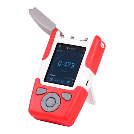
Field Service Fiber Optic Power Meter Chapter 4 Operation Figure 11 Attenuation Numerical Entry and Alphanumerical Entry Power Measurements The main measurement screen shows a large digit numerical representation of the actual power value, supported by a circular level display indicating the level within the selected measurement range. All settings can be done with the button carousel in the footer menu. -
Page 27: Peak And Top Mode
Field Service Fiber Optic Power Meter Chapter 4 Operation Figure 12 Main Measurement Screen and Information Overlay. 4.6.2 Peak and Top Mode To perform peak power measurements, browse to the first footer menu by left arrow, swiping the menu to the right side, or navigating with the physical buttons. -
Page 28: Visual Fault Locator (Pm61 Series Only)
Field Service Fiber Optic Power Meter Chapter 4 Operation 4.6.3 Visual Fault Locator (PM61 Series Only) The visible laser can be switched on by the left button in the measurement screen. When the laser is on, it is not possible to switch screens until it is turned off. Switch between the CW and 1 Hz / 3 Hz flashing modes by pressing the right setup button. -
Page 29: Statistics
Field Service Fiber Optic Power Meter Chapter 4 Operation Figure 16 Data Logging 4.7.2 Statistics In combination with the graphical representation of the data logging, there is a statistic view on the same set of data. During and after the record it is possible to switch between both views by swiping right or left or navigating over the dots in the header line. - Page 30 Field Service Fiber Optic Power Meter Chapter 4 Operation Pass/Fail Analysis (PM61 Series Only) The pass-fail analysis function is an extremely useful tool for quality control in production and service. It gives visual attention to whether the measurement value is within a predefined power range without the need of reading the exact power value.
- Page 31 Field Service Fiber Optic Power Meter Chapter 4 Operation Figure 19 PM61 Pass-Fail Analysis for Relative Power Levels (Loss) In both cases, it is possible to record the measurements to a file on the internal flash memory. Therefore, the admin user can configure the stop condition and the measurement interval in the logging menu for themself and for the ordinary users.
-
Page 32: 4.10.1 Usb 2.0 Interface
All Thorlabs optical power meters are devices that follow the USBTMC (test & measurement class) protocol. This is a USB device class that allows communication with testing and measuring devices, using SCPI (Standard Commands for Programmable Instruments) commands. -
Page 33: Bluetooth Interface (Pm61 Series Only)
On Windows PCs, as well as on mobile devices, it will show as “PM61”. Connect to the found PM61 Series device. Communication is then possible via SCPI commands, using the drivers, or using an app. The Thorlabs optical power meter software can also be used to communicate via Bluetooth low energy. - Page 34 Do not mechanically rub on any diffused surfaces, this may lead to changes in the sensor responsivity! Cleaning the VFL Connector The visual fault locator has a built-in ferrule tip that can be cleaned using a mechanical cleaner like the Thorlabs FBC250. Risk of Eye Damage Verifying the surface of the connector with a fiber-optic microscope while the unit is active may result in permanent eye damage.
- Page 35 Field Service Fiber Optic Power Meter Chapter 5 Maintenance and Cleaning 1. If applicable, disconnect attached USB cables and optical fibers. 2. Turn off the unit. 3. Place the unit on a level and tidy surface, positioning the display facing downward. 4.
- Page 36 2. Connect the USB cable to a free port of the computer and to the PM60 or PM61 series. 3. Download the new firmware package from the Thorlabs website to your local drive. 4. Open the optical power meter software.
-
Page 37: Chapter 6 Troubleshooting And Repair
Field Service Fiber Optic Power Meter Chapter 6 Troubleshooting and Repair Chapter 6 Troubleshooting and Repair Below are a few checks to help in troubleshooting problems that may arise. Please contact your local Thorlabs Technical Support office with any questions. Failure Troubleshooting Unit Does Not Turn On Ensure that the battery is sufficiently charged;... -
Page 38: Chapter 7 Disposal
Contact Thorlabs for more information. Waste treatment is your own responsibility. “End of life” units must be returned to Thorlabs or handed to a company specializing in waste recovery. Do not dispose of the unit in a litter bin or at a public waste disposal site. It is the user’s responsibility to delete all personal data stored on the device prior to disposal. -
Page 39: Chapter 8 Thorlabs Worldwide Contacts
Field Service Fiber Optic Power Meter Chapter 8 Thorlabs Worldwide Contacts Chapter 8 Thorlabs Worldwide Contacts For technical support or sales inquiries, please visit us at www.thorlabs.com/contact for our most up-to-date contact information. Corporate Headquarters Product Manufacturer Thorlabs, Inc. Thorlabs GmbH 43 Sparta Ave Münchner Weg 1... - Page 40 www.thorlabs.com...
Need help?
Do you have a question about the PM60A and is the answer not in the manual?
Questions and answers