LEMKEN Juwel 8M Operating Instructions Manual
Mounted reversible ploughs
Hide thumbs
Also See for Juwel 8M:
- Instruction manual (136 pages) ,
- Operating instructions manual (134 pages) ,
- Operating instructions manual (125 pages)
Table of Contents

Subscribe to Our Youtube Channel
Related Manuals for LEMKEN Juwel 8M


Summary of Contents for LEMKEN Juwel 8M
- Page 1 Operating Instructions Mounted Reversible Ploughs Juwel 8M / 8M V - en - Item no. 17511275 01/07.17 LEMKEN GmbH & Co. KG Weseler Straße 5, 46519 Alpen / Germany Telephone +49 28 02 81 0, Fax +49 28 02 81 220...
- Page 3 However, this brief instruction is not a substitute for thorough study of the operating instructions. These operating instructions will help to familiarise you with the LEMKEN GmbH & Co. KG device and the options available for using it.
- Page 4 Remember that you should only use genuine LEMKEN spare parts. Reproduction parts have a negative influence on the function of the device, have a shorter ser- vice life and present risks and hazards that cannot be estimated by LEMKEN GmbH & Co. KG. They also increase the maintenance costs.
-
Page 5: Table Of Contents
CONTENTS General information ....................9 Liability ........................... 9 Guarantee ........................9 Copyright ........................10 Optional accessories ....................10 Type plate ........................11 Symbols used in the Operating Instructions ............13 Hazard classes ......................13 Information........................13 Environmental protection ................... 13 Indication of passages .................... - Page 6 3.8.2 Requirements of the tractor ..................25 3.8.3 Axle loads ........................26 3.8.4 Check before departure ..................... 30 3.8.5 Correct behaviour in road traffic ................30 Obligation of the operator ..................30 3.10 Safe use of the implement ..................31 3.10.1 General ........................
- Page 7 Required power sources .................... 50 6.8.1 Determining axle loads and required ballasting ............50 Preparing the implement ..................51 Initial start-up ....................... 51 Depth wheel or depth and transport wheel ............... 51 Skimmer ........................51 Attaching the implement ..................52 Specific safety information..................
- Page 8 DuraMaxx plough body ..................80 11.9.2 DURAL plough body ....................82 11.10 Working width for each body ..................84 11.10.1 Juwel 8M V ......................84 11.10.2 Juwel 8M ......................85 11.11 Landside ........................87 11.12 Sword coulter ......................89 11.13 Trashboard........................90 11.14 Subsoilers ........................
- Page 9 11.18.3 Working depth adjustment ................110 12 Overload safety devices ..................114 12.1 Shearing protection ....................114 12.2 Mechanical non-stop overload safety device ............116 12.3 Hydromatic hydraulic overload protection ............. 117 12.3.1 General ........................ 117 12.3.2 Setting the release force ..................118 12.3.3 Operation......................
- Page 10 15.6 Hydromatic overload protection - depressurising the hydraulic system ..... 129 15.7 Check the connections to the tractor ..............130 15.7.1 Hydraulic connections ..................130 15.7.2 Electrical connections ................... 130 15.7.3 Lubrication chart ....................131 16 Troubleshooting ....................132 16.1 Hydraulic equipment ....................132 16.2 Plough intake and depth control, slippage .............
-
Page 11: General Information
Co. KG, in particular Section IX, shall apply. Liability. In line with the dimensions cited in these conditions the LEMKEN GmbH & Co. KG shall not be held liable for any personal or material damage, when such damage is caused by one or more of the following reasons: •... -
Page 12: Copyright
Infringements will result in a claim for damages. Optional accessories LEMKEN implements may be equipped with various accessories. The operating instructions below describe both series components and optional accessories. Please note: These accessories will vary depending on the type of equipment. -
Page 13: Type Plate
General information Type plate The implement carries a type plate. The type plate can be found at front right on the implement. The operating instructions may apply to different implement types or variants of the implement. The operating instructions indicate infor- mation which only applies to a specific im- plement type or a specific variant of the implement. - Page 14 General information Layout of the type plate Illustration: Example of a type plate Illustration: Example of a type plate, France only 1 Series 2 Type designation 3 Serial number 4 Year of manufacture 5 Permissible drawbar load [kg] 6 Permissible axle load [kg] 7 Permissible gross weight [kg] 8 Company logo and address 9 CE marking...
-
Page 15: Symbols Used In The Operating Instructions
Symbols used in the Operating Instructions SYMBOLS USED IN THE OPERATING INSTRUCTIONS Hazard classes The following symbols are used in the Operating Instructions for particularly im- portant information: DANGER Denotes an imminent hazard with high risk, which will result in death or severe physical injury, if not avoided. -
Page 16: Indication Of Passages
Symbols used in the Operating Instructions Indication of passages The following symbols are used for particular passages in the operating instruc- tions: − Indicates work steps • Indicates enumerations... -
Page 17: Safety Measures And Precautions
Safety measures and precautions SAFETY MEASURES AND PRECAUTIONS General safety instructions for the operator are specified in the chapter entitled «Safety measures and precautions». At the start of some main chapters the safety instructions, which refer to all work to be carried out in this chapter, are listed to- gether. -
Page 18: Safety Features Of The Device
Safety measures and precautions Safety features of the device To protect the operator and the device, the device is equipped with special safety features in accordance with country specific requirements. − Always keep all safety devices in working order. Safety and warning stickers 3.4.1 General The implement features all equipment which ensures safe operation. -
Page 19: Position Of Warning Stickers
Safety measures and precautions 3.4.2 Position of warning stickers Version with pressure accumulator Version with attachment arm for furrow press... -
Page 20: Meaning Of Warning Signs
Safety measures and precautions 3.4.3 Meaning of warning signs − Please familiarise yourself with the meaning of the warning signs. The following explanations provide detailed information. Please read and observe the operating in- structions and safety instructions before starting up the implement for the first time. Before carrying out maintenance or repair work, switch off the engine and remove key. - Page 21 Safety measures and precautions When the three-point power lift is activat- ed, stay outside of the lifting range of the three-point suspension. Keep well clear of the turning and swinging area of the implement. Hydraulic accumulator contains gas and oil under pressure.
-
Page 22: Meaning Of Other Symbols
Safety measures and precautions 3.4.4 Meaning of other symbols. Load-securing points Sling points Locating points for fork-lift Hydraulic equipment The Optiquick adjustment centre... -
Page 23: Special Safety Instructions
Safety measures and precautions Special safety instructions Risk of injury due to non-observance of the currently valid occupational safety guidelines If the currently valid occupational safety guidelines are bypassed WARNING or safety equipment is rendered unusable when handling the de- vice, there is a risk of injury. - Page 24 Safety measures and precautions Risk of injury when freeing casualties When rescuing people trapped or injured by the device, there is a risk of additional serious injury to the casualty if the hydraulic con- nections were not connected according to their colour coding as described in the section entitled "Required hydraulic equipment".
-
Page 25: Danger Areas During Implement Operation
Safety measures and precautions 3.5.1 Danger areas during implement operation Moving danger area The danger area around the implement moves with the implement during operation. The danger area includes the area extending across the entire width (a) of the implement in the direction of WARNING travel. -
Page 26: Hazard Caused By Mechanical Systems
Safety measures and precautions 3.6.1 Hazard caused by mechanical systems There is a risk of accidents due to crushing, cutting and striking body parts − on abruptly moving machine parts, − on moving machine parts caused by stored mechanical energy in elastic parts, such as springs, −... -
Page 27: Operation On Public Highways
Safety measures and precautions Operation on public highways 3.8.1 Lighting system and identification A proper lighting system, identification and equipment must be on the device if it is to be transported on public roads. Further information can be requested from the appropriate authorities. -
Page 28: Axle Loads
Safety measures and precautions 3.8.3 Axle loads Implements mounted to the front and rear three-point linkage must not result in the following being exceeded: • permissible gross weight of tractor, • permissible axle loads of tractor, • the tractor's tyre load-carrying capacities. The tractor's front axle must always be loaded with at least 20 % of the tractor's curb weight. - Page 29 Safety measures and precautions Data from tractor operating instructions − Take the following data from your tractor's operating instructions: Abbreviation Data Tractor kerb weight (kg) _______ kg Front axle load (kg) of empty tractor _______ kg Rear axle load (kg) of empty tractor _______ kg Data from implement operating instructions −...
- Page 30 Safety measures and precautions Calculation of minimum ballasting value at front G for rear mounting V min implement x (c + d) – T x b + (0.2 x T x b) V min a + b − Enter the calculated minimum ballasting value, as required at the front of the tractor, into the table.
- Page 31 Safety measures and precautions Calculation of actual rear axle load T H tat H tat V tat − Enter the value for the calculated actual rear axle load and the permissible rear axle load as given in the tractor's operating instructions into the table. Tyre load-carrying capacity −...
-
Page 32: Check Before Departure
Safety measures and precautions 3.8.4 Check before departure − Before driving with the implement raised, lock the control lever of the control unit; otherwise it may drop and the implement may be unintentionally lowered. − Mount and check the transport equipment such as the lighting system, warning signs and protective devices. -
Page 33: Safe Use Of The Implement
Safety measures and precautions The operating instructions are an important component of the device. − Ensure that the operating instructions are always ready available at the installa- tion location of the device and are kept for the entire service life of the device. −... -
Page 34: Personnel Selection And Qualifications
Safety measures and precautions − Do not stand between the tractor and implement when operating the external controls for the three-point linkage. Do not stand in the danger area around the implement or climb onto the imple- ment during operation. There is a risk of injury in the wider operating area around the implement, e.g. -
Page 35: Hydraulic System
Safety measures and precautions 3.10.3 Hydraulic system • The hydraulic system is under high pressure. • When connecting hydraulic cylinders and motors, ensure that the specified hy- draulic hose connection is used. • When connecting the hydraulic hoses to the tractor hydraulics, make sure that the hydraulic system is depressurised on both the tractor and the implement. -
Page 36: Handing Over The Implement
Handing over the Implement HANDING OVER THE IMPLEMENT − As soon as the implement is delivered, ensure that it corresponds with the order package. − Also check the type and completeness of any supplied accessories. When the device is handed over, your dealer will explain how it works. −... -
Page 37: Layout And Description
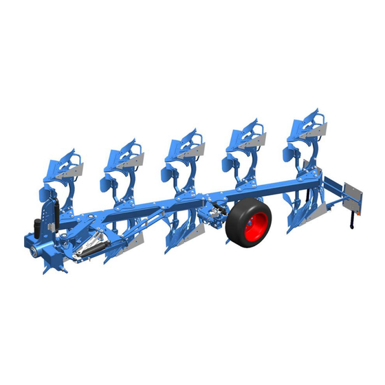
Layout and description LAYOUT AND DESCRIPTION 1 Headstock 7 Additional tools (skimmer, trashboard) 2 Cross shaft 8 Disc coulters 3 Basic frame 9 Overload safety device - variant X shown 4 Turnover device 10 The Optiquick adjustment centre 5 Depth wheel 11 Lighting equipment 6 Plough body... -
Page 38: Description
The ploughs of the Juwel 8M series feature a square profile tube 140 x 140 x 10 mm. The frame height is 80 cm or optionally 85... -
Page 39: Stand
(1). The stand (1) ensures safe positioning af- ter dismantling the implement and is re- folded up while in a mounted state. 5.1.4 Turnover device The ploughs of the Juwel 8M series feature the hydraulic turnover device M 120. -
Page 40: Depth Wheel
The depth wheel performs only one touch function. The following depth wheels are intended for the ploughs of the Juwel 8M series: • Depth control wheel hydraulically dam- • Depth and transport wheel hydraulically damped • Depth and transport wheel hydraulically... -
Page 41: Plough Body
Layout and description 5.1.6 Plough body DuraMaxx The strips (1) or mould boards (2) are at- tached to the mould board (4) with hooks (3). Accordingly, replacement without tools is possible. - Page 42 Layout and description Dural The plough body consists of: • Mouldboard, made up of a shin (1) and a mouldboard (2), or slats (5). • Share, made up of a wing (3) and a point (4). • Frog (6) • Landside (7)
-
Page 43: Additional Tools
Layout and description 5.1.7 Additional tools The following additional tools are available as accessories: Trashboard (1) Skimmer (2) Sword coulter (3) -
Page 44: Disc Coulters
Layout and description 5.1.8 Disc coulters The large, ribbed disc coulter ensures a clean furrow. Version with smooth disc coulter (1), rigid leg (2). Version with serrated disc coulter (1), spring-loaded leg (2). -
Page 45: Overload Safety Devices
Layout and description 5.1.9 Overload safety devices The overload safety device protects the basic frame and the plough body from overload. The double-cut shearing protection (1) in the leg brackets is available as standard on all Juwel ploughs. The shear bolt is re- placed after a breakage, see «Shearing protection, page 114». -
Page 46: The Optiquick Adjustment Centre
Layout and description 5.1.10 The Optiquick adjustment centre The draw point and the front furrow width can be adjusted independently of each other. Ploughing without side pull is there- fore possible at any working width. Standard version with mechanical adjust- ment for the draw point (1) and mechanical adjustment for the front furrow width (2). -
Page 47: Lighting Equipment
Layout and description 5.1.11 Lighting equipment The lighting equipment (1) makes a signifi- cant contribution to increasing the safety of the implement while driving on public roads. Version with depth control wheel. Version with depth and transport wheel. -
Page 48: Preparations On Tractor
Preparations on tractor PREPARATIONS ON TRACTOR Tyres The air pressure must be identical, particularly on the rear tractor tyres. Under dif- ficult conditions, additional wheel weights should be used or the tyres topped up evenly with water. See operating instructions of the tractor manufacturer. Lifting rods The lifting rods should be adjusted so they are as short as possible and of equal length. -
Page 49: Checking The Tractor's Three-Point Linkage
Preparations on tractor Checking the tractor's three-point linkage Danger of accident due to loss of implement WARNING Driving over uneven terrain or vibrations may cause the cross shaft and top link pin to slip out of the threepoint linkage. This may result in accidents with injuries or death of persons or damage to the implement. -
Page 50: Hydraulics
Preparations on tractor Risk of accident due to high tractor power WARNING Tractors with a three-point linkage, which has an excessively high category, and excessively high tractor power may overload the components of the implement. This may cause the components to break. -
Page 51: Required Hydraulic Equipment
Preparations on tractor Required hydraulic equipment The implement is supplied as standard with separate hydraulic connections for each consumer. The protecting caps for the hydraulic connections are colour- coded and the hydraulic connections themselves are alphanumerically coded. For operation of the specific hydraulic equipment listed below, the tractor must be equipped with the following spool valves: Function Plough... -
Page 52: Required Power Sources
Preparations on tractor Required power sources The following power sources are required on the tractor for the electrical consum- ers: Consumer Volts Direct connection to Power socket the tractor battery Lighting equipment As per DIN ISO 1724 6.8.1 Determining axle loads and required ballasting Risk of accidents due to inadequate steerability A tractor with insufficient front axle load cannot be steered proper- ly. -
Page 53: Preparing The Implement
Preparing the implement PREPARING THE IMPLEMENT Initial start-up For transportation-specific reasons, the implement is not always delivered in a ful- ly-assembled condition. The implement must not be started up until it has been completely assembled and has undergone a performance check. When starting up the implement for the first time, it is recommended to make the following adjustments before commissioning the implement on the farm and to familiarise yourself with the implement and its functions. -
Page 54: Attaching The Implement
Attaching the implement ATTACHING THE IMPLEMENT Specific safety information Risk of injury from the parked implement − Never enter the danger zone between the tractor and imple- ment. WARNING − Read and observe the "Safety measures and precautions" sec- tion and the special safety instructions "Risk of injury from the parked implement". - Page 55 Attaching the implement Work instruction − Switch hydraulic system of the threepo- int linkage for attachment of the imple- ment to position control. − Drive tractor backwards towards the im- plement until the tractor is directly in front of the implement and the catch hooks of the lower links can be connect- ed to the cross shaft (1).
- Page 56 Attaching the implement − Pull out locking bar (3) with a rotating movement. − Swing up the stand (2). − Secure stand with locking bar (3). Adjust top link to correct length. Plough is parked on level ground. − Lower plough. −...
- Page 57 Attaching the implement − Attach lighting equipment and warning boards when driving on public roads. See «Attaching the lighting equipment, page 61». When working in the field, the tractor hydraulics must always be switched to draft control or mixed control.
-
Page 58: Uncoupling The Implement
Uncoupling the implement UNCOUPLING THE IMPLEMENT Specific safety information Risk of injury from the parked implement − Never enter the danger zone between the tractor and imple- ment. WARNING − Read and observe the "Safety measures and precautions" sec- tion and the special safety instructions "Risk of injury from the parked implement". - Page 59 Uncoupling the implement DANGER If subsoilers have been mounted, the parked im- plement may overturn. Before removing the plough, the subsoilers must be turned over: − Release the locking bar (2). DuraMaxx − Pull out subsoiler (1). − Insert subsoiler (1) from above into the holder (3).
- Page 60 Uncoupling the implement − Hold the stand (6) firmly with one hand. − Pull out locking bar (7) with a rotating movement. − Swivel down stand. − Secure stand with locking bar. − Lower the bottom links, until the stand is resting on the ground.
-
Page 61: Driving On Public Highways
Driving on public highways DRIVING ON PUBLIC HIGHWAYS 10.1 General information A proper lighting system, identification and equipment must be on the implement, if it is to be transported on public roads. The country-specific valid laws and regu- lations pertaining to driving on public roads must be observed. 10.1 Laws and regulations All laws and regulations concerning transportation on public roads must be ob-... -
Page 62: Switching Depth And Transport Wheel
Driving on public highways 10.4.1 Switching depth and transport wheel If the front axle is relieved too much and this results in inadequate steerability of the tractor, always use a depth and transport wheel. When driving on public roads, the depth and transport wheel is used as a transport wheel. -
Page 63: Attaching The Lighting Equipment
Driving on public highways 10.4.2 Attaching the lighting equipment The lighting equipment can be attached in the working position. Version with depth control wheel To prevent damage, the implement must always be lifted before the lighting equipment is attached or removed. Version consisting of equipment with depth control wheel −... -
Page 64: Subsoilers
Driving on public highways 10.4.3 Subsoilers Before driving on public roads, the subsoil- ers must be turned over: − Release the locking bar (2). − Pull out subsoiler (1). − Insert subsoiler (1) from above into the holder (3). − Secure subsoiler (1) with the locking bar (2). -
Page 65: Operation
Operation OPERATION 11.1 Specific safety information − Read and observe the "Safety measures and precautions" sec- tion. CAUTION • This implement should always be used, operated and repaired by persons who are familiar with it and aware of the risks. •... -
Page 66: Rotating Plough Frame
Operation 11.2 Rotating plough frame − Refer to the safety and protective measures, see page 15. DANGER − Before each turning process, ensure that there are no persons in the turning and swivelling area of the plough. − Activate the turnover device from the tractor seat only. −... - Page 67 Operation − When the plough frame has been turned, switch control lever to "N" (Neu- tral). Another turning process can then be start- WARNING In conjunction with a frame swivelling cylinder, the plough frame first swivels inward before the turning process and swivels out again after the turning process.
-
Page 68: Adjusting Front Furrow Width
Operation 11.3 Adjusting front furrow width The front furrow width (2) must be adjusted using the Optiquick adjusting system (1) to correspond to the working width of the fol- lowing plough bodies. 11.3.1 Implement with mechanical frontfurrowadjustment The front furrow width is adjusted using the outer turnbuckle. •... -
Page 69: Implement With Mechanical Frontfurrowadjustment In Conjunction With Hydraulic Frame Swing-In
Operation 11.3.2 Implement with mechanical frontfurrowadjustment in conjunction with hydraulic frame swing-in The front furrow width is adjusted using the adjuster sleeve on the hydraulic ram. This ram is hydraulically connected to the ram of the turnover device. DANGER Basic frame first swivels in before turning and then swivels out again. -
Page 70: Implement With Hydraulic Frontfurrowadjustment
Operation − Retighten clamping screw (2), see «Tightening torques, page 127» − Retract hydraulic ram (4). To do this, ac- tuate the spool valve for the turnover ram and pressurise connection T1. 11.3.3 Implement with hydraulic frontfurrowadjustment The front furrow width is adjusted using the hydraulic ram. •... -
Page 71: Tractor/Plough Traction Line
Operation 11.4 Tractor/plough traction line The plough has been optimally set when the tractor/plough traction line – the con- nection line between Z and PZ – runs through the middle of the back tractor axle The tractor/plough traction line must be set using the inner turnbuckle (1) so that there is no more side pull. -
Page 72: On-Land Design (Of)
Operation 11.5 On-land design (OF) 11.5.1 General information The implements can also be supplied with an on-land design. This configuration me- ans the implement can be used: • O-operation = on-land, letting you • F-operation = letting you use the tractor use the tractor outside the furrow within the furrow The OF plough comes complete with:... -
Page 73: Switching F-Operation To O-Operation / O-Operation To F-Operation
Operation 11.5.2 Switching F-operation to O-operation / O-operation to F-operation During the switchover process, the implement is swivelled and ro- DANGER tated. This may result in accidents causing injuries or fatalities. − Before each switching, ensure no persons are present within the area of rotation and swivelling of the plough. - Page 74 Operation Switching O- to F-operation − Extend the internal hydraulic cylinder (2) until the front furrow width is correctly adjusted. − Adjust tractor/plough pull line with the external hydraulic cylinder (3). See «Side pull correction , page 75». − Open (4) ball valve.
-
Page 75: Adjustment Centre
Operation 11.5.3 Adjustment centre The adjustment centre allows the plough to be adapted to the respective working con- ditions. The front furrow width is adjusted using the internal hydraulic cylinder (1). The front fur- row width must be adjusted with the ad- justment centre such that it corresponds to the working width of the following plough bodies. - Page 76 Operation F-operation Adjusting front furrow width Adjust the front furrow width (S) with the internal hydraulic cylinder (1): Front furrow too wide: − Retract hydraulic cylinder (1). Front furrow too narrow: − Extend hydraulic cylinder (1). o The front furrow width (S) cor- responds to the working width of the following plough bodies.
- Page 77 Operation Side pull correction / Adjust trac- tor/plough pull line Adjust tractor/plough pull line with the ad- justing element (4) of the external hydraulic cylinder (2), so that no more side pull is present: − Lower the implement to the ground. −...
-
Page 78: Inclination
Operation O-operation Distance between the tractor and the furrow border Adjust the distance of the tractor from the furrow border (S) using the internal hydrau- lic cylinder (2). Distance to the furrow border too narrow: − Retract hydraulic cylinder (2). Distance to the furrow border too wide: −... - Page 79 Operation The inclination is mechanically adjusted using two adjusting nuts (3) and is imple- mented separately on both sides. − Briefly pressurise hydraulic connection P1 of the turnover ram (1). o Plough lifts approx. 5 – 10 cm. o The stop arm (2) rotates a few centimetres away from the stop.
-
Page 80: Working Depth
Operation 11.7 Working depth The working depth is adjusted using the hydraulic system and the depth wheel on the plough, see «Working depth adjustment, page 110». For information on ad- justing the hydraulic system, see the operating instructions from the relevant trac- tor manufacturer. - Page 81 Operation − Apply pressure to connection P1 until the basic frame has turned completely and swung out again. When the working width of the Juwel V is changed, the tractor's three-point linkage shifts sideways for automatic adjustment of the front furrow width and tractor-plough pull line.
-
Page 82: Pitch Angle
Operation 11.9 Pitch angle 11.9.1 DuraMaxx plough body The pitch angle is adjusted via the position of the eccentric plate. The bodies are fitted at a centre pitch angle relative to the ground. The eccentric plate (1) is in the centre position, see notch on the eccentric plate. - Page 83 Operation • Smaller pitch angle: − Rotate eccentric plate (1) upwards by 90°. Notch points in the direction of the plough frame. o Improved depth control. − After adjusting the pitch angle, tighten nuts (2) and (3). Tightening torques see «Tightening torques, page 127»...
-
Page 84: Dural Plough Body
Operation 11.9.2 DURAL plough body The bodies are fitted at a centre pitch - angle relative to the ground. If required, the pitch angle can be changed using the two adjusting screws (1a, 1b). − Undo the screw (2). The bolted connection (3) is used as a piv- ot when adjusting the pitch angle. - Page 85 Operation All plough bodies must be adjusted to the same pitch angle. − Adjust pitch angle of the first and last plough body. − Measure distance between point and plough frame (= reference dimension) − Adjust the remaining plough bodies ac- cording to this reference dimension.
-
Page 86: Working Width For Each Body
Operation 11.10 Working width for each body 11.10.1 Juwel 8M V The working width for each body can be changed where required from the tractor using the working width adjusting cylinder (1). Preconditions The basic adjustment of the plough is made using the Optiquick adjustment cen- tre. -
Page 87: Juwel 8M
Operation 11.10.2 Juwel 8M To set different working widths, the leg brackets of the individual plough bodies have holes for four different attachment positions. The position of the depth wheel must be adjusted accordingly. Four different working widths can be set. - Page 88 Operation − Tighten screws, see «Tightening tor- ques, page 127». Version depth and transport wheel, hy- draulic Adjust the position of the depth and transport wheel as follows − Undo the screw (4). − Swivel the swivel arm (5) with control rod (6) into the correct position.
-
Page 89: Landside
Operation Hole Working width Working width Working width At 90 cm At 100 cm At 120 cm body dis- body distance body distance tance 11.11 Landside For better guidance on slopes, move land- side DMV1 (1) to a lower position (only possible with DuraMaxx plough bodies.) −... - Page 90 Operation Landside DMV2 (4) remains in this position even on slopes. Landside DMV2 All landsides must be set in the same position.
-
Page 91: Sword Coulter
Operation 11.12 Sword coulter The landside wedge must be removed be- fore the sword coulter is attached. − Unscrew countersunk screw (5) and hexagon bolt (4). − Remove landside wedge (1) and hexa- gon bolt (4). − Attach sword coulter (2) in front of the landside (3) and screw into place using both hexagon bolts (5). -
Page 92: Trashboard
Operation 11.13 Trashboard The trashboard (1) is attached to the mouldboard (3) via the holder (2). The slots (4) on the holder allow universal ad- justment. All trashboards must be set in the same position. Version DuraMaxx − Align trashboard (1) with holder (2) via the slots (4) and screw onto the leg (3). - Page 93 Operation Version Dural − Align trashboard (1) with holder (2) via the slots (4) and screw onto the mould- board (3). − Adjust trashboard to prevent crop resi- due between the slats or mouldboard and trashboard o The edge of the trashboard is positioned on the mouldboard or mouldboard slat.
- Page 94 Operation The support bolt (4) supports the trash- board against the leg. − Secure support bolt (4) with lock nut (5), see view Y. The installation position of the support bolt and the lock nut may vary de- pending body shape used.
-
Page 95: Subsoilers
Operation 11.14 Subsoilers Subsoilers are mounted on the leg. The depth of the subsoilers can be adjusted. The leg is protected from wear by the leg guard. Leg guard and subsoiler can be re- placed later. Adjusting the working depth −... -
Page 96: Wide Furrow Cutter
Operation 11.15 Wide furrow cutter The wide furrow cutter (1) widens the fur- row made by the last body. It can be used in light to medium soils without any prob- lems. It cannot be used effectively in heavy soil conditions. The wide furrow cutter (1) is attached to the last body on the plough. -
Page 97: Skimmers
Operation 11.16 Skimmers 11.16.1 General information The skimmers (1) should penetrate the soil by approx. 5 - 10 cm and in the top view are approx. 2 to 3 cm from the side of the landside on the plough body. If you want to plough e.g. -
Page 98: Working Depth
Operation 11.16.2 Working depth Risk of crushing CAUTION When adjusting the working depth, the skimmer can drop down after removal of the guide pin (4). − Hold skimmer firmly with one hand until it is secured by insert- ing the guide pin (4). When adjusting the working depth, the projection anglesetting does not change. -
Page 99: Projection Angle Adjustment
Operation 11.16.4 Projection angle adjustment On the standard version the projection an- gle of the skimmers cannot be adjusted. On the version with projection angle ad- justment the skimmers (1) are connected to their flat stalks (2) and the swivel brack- et (3) is connected by a pivot to the bracket (4). -
Page 100: Disc Coulters
Operation 11.17 Disc coulters 11.17.1 General information The disc coulters have been set for operation at the factory with the following ad- justment dimensions. Make subsequent adjustments to the disc coulters only when changing the setup state. The working depth (T) of the disc must be set between 7 cm and 12 cm. -
Page 101: Working Depth
− Swivel coulter arm (1) as required. Rigid disc coulter (Juwel 8M) Ensure that the teeth on the coulter arm (1) mesh exactly with the adjacent toothed bracket (3) before tightening the screw (2). Spring-loaded disc coulter (Juwel 8M T) -
Page 102: Side Distance
− Undo the screw (3). Adjust lateral clearance. − Move coulter stalk (2) in the slot (a) until the required position has been reached. − Retighten screw (3), see «Tightening torques, page 127». Rigid disc coulter (Juwel 8M) Spring-loaded disc coulter (Juwel 8M T) -
Page 103: Swivel Restriction
Version disc coulter next to skimmer o Disc coulter (1) can be swiv- elled up to the skimmer (4). Ad- just the adjusting piece (2) so that the swivel area is limited up to this point. Rigid disc coulter (Juwel 8M) - Page 104 (1), when swivelled in, points to- wards the point on the skimmer (4). Spring-loaded disc coulter (Juwel 8M T) Version without skimmer o Adjust the adjusting piece so that the disc coulter, when swivelled in, points towards the...
-
Page 105: Depth Wheel And Depth And Transport Wheel
Operation 11.18 Depth wheel and depth and transport wheel The plough can be supplied with a depth wheel (1) or depth and transport wheel. The depth and transport wheel must al- ways be used if the front axle - particularly during road transport - is relieved too much and this results in inadequate steerability of the tractor. - Page 106 Operation Switching hydraulic depth and transport wheel from working to transport position − Rotate plough into the right-turning work- ing position and park on the ground. − Remove retaining pin (2). − Lift up plough o Hydraulic ram (1) is detached from the wheel stalk (3).
- Page 107 Operation Switching hydraulically damped depth and transport wheel from working to transport position − Rotate plough into the right-turning work- ing position. − Park plough on the ground. − Remove retaining pin (2). − Detach hydraulic damper (1) from the wheel stalk (3).
- Page 108 Operation Moving plough into the transport position To ensure that the plough is locked in the centre position during transport, the locking device on the tower is turned from the working position (A) into the transport posi- tion (B). − Pull up detent pin (9). o Lever (10) swivels back into position B.
-
Page 109: Switching Depth And Transport Wheel From Transport To Working Position
Operation 11.18.2 Switching depth and transport wheel from transport to working position Moving plough into the working position − Connect top link to the headstock. − Secure top link with the top link pin (11). − Lift up plough. − Pull lever (10) until the detent pin (9) en- gages in the designated hole. - Page 110 Operation Switching hydraulic depth and transport wheel from transport to working position − Pull out pin (7). − Swivel depth and transport wheel by 90° towards the plough frame. − Lock the depth and transport wheel in this position with the pin (7). −...
- Page 111 Operation Switching hydraulically damped depth and transport wheel from transport to working position − Rotate plough into the rightturning work- ing position. − Pull out pin (4). − Swivel depth and transport wheel by 90° towards the plough frame. − Lock the depth and transport wheel in this position with the pin (4).
-
Page 112: Working Depth Adjustment
Operation 11.18.3 Working depth adjustment Pendulum wheel − Remove the socket pin (2). − Move the depth adjustment wheel (1) by the same amount on both sides. • Move the depth adjustment wheel (1) towards the wheel axle (downwards) => increases the working depth •... - Page 113 Operation Depth adjustment table Depth adjustment Ratchet position cm (total) to set depth Difference from pre- position (1) vious position, cm 11.2...
- Page 114 Operation Depth adjustment Ratchet position cm (total) to set depth Difference from pre- position (1) vious position, cm 12.7 15.3 18.3 19.7 21.5 24.5 26.4 27.9 29.5 31.6 33.1 34.8 36.9 38.5 40.2...
- Page 115 Operation Uni wheel hydraulically dampened − Remove the linch pin (3). − Remove the pin (2). − Fix the stop (1) in the required position using the pin (2). If finer adjustment is required, the position of the stop (1) can be changed. −...
-
Page 116: Overload Safety Devices
WARNING: Risk of crushing from mov- ing parts. Working in front of the plough Juwel 8M body as seen in the direction of travel may result in serious injuries. − Loosen screw (2) on the leg. Juwel 8M X... - Page 117 Overload safety devices Juwel 8M T − Lift up implement until the plough body swivels back into its working position. − Have a new shear bolt (1) ready. Use only shear bolts which have the specified dimensions and quality, as only these bolts will provide effective protection against damage, see «Permitted shear bolts for overload safety device,...
-
Page 118: Mechanical Non-Stop Overload Safety Device
Overload safety devices 12.2 Mechanical non-stop overload safety device The release force of the plough body can be adjusted steplessly via the pretension of the spring assemblies. When an obstacle is encountered, the body avoids it by moving upwards. Crushing and shearing points in the release area! DANGER Springs are under tension! −... -
Page 119: Hydromatic Hydraulic Overload Protection
Overload safety devices 12.3 Hydromatic hydraulic overload protection − Read and follow the “Safety and protection measures” section, and the specific safety information “Hazards associated with hydraulic systems”. − Do not stand within the trip range of the plough bodies while the plough is operating. -
Page 120: Setting The Release Force
Overload safety devices 12.3.2 Setting the release force Different operating pressures can be set using the hydraulic overload safety de- vice: • Low operating pressure for light and shallow soil conditions • High operating pressure for heavy soil conditions The operating pressure must be at least 125 bar. Standard version with hydraulic overload safety device Hydromatic The shut-off valve on the headstock is used to adjust both the turnover device... - Page 121 Overload safety devices Once the adjusting valve unit has been connected to a tractor spool valve, the sys- tem is ready for operation with the factory- set maximum and minimum operating pressure. These operating pressures can be adjusted to meet individual require- ments using the rotary knobs (2 and 3).
-
Page 122: Operation
Overload safety devices 12.3.3 Operation To protect the hydraulic system, the plough and the tractor itself, always work at the lowest possible operating pressure. The maximum operating pressure is set by applying pressure to connection A on the valve adjusting unit for several seconds. The minimum operating pressure is set by applying pressure to connection B on the valve adjusting unit for several seconds. -
Page 123: Attachment Arm
Attachment arm ATTACHMENT ARM CAUTION − Read and observe the "Safety and protection measures", page 15. The attachment arm swivels to the catch position by spring force. − Ensure that an adequate safety distance is maintained. − Insert attachment arm (1) on the front of ploughframe into locating... -
Page 124: Put The Implement Out Of Operation
Put the implement out of operation PUT THE IMPLEMENT OUT OF OPERATION 14.1 Shutting down the implement in an emergency − In an emergency shut down the implement via the tractor. − Switch the tractor engine off. − Remove the ignition key. Damage caused by improper storage of the implement If incorrectly or improperly stored, the implement may be dam- CAUTION... -
Page 125: Maintenance And Repairs
Maintenance and repairs MAINTENANCE AND REPAIRS 15.1 Special safety instructions 15.1.1 General Risk of injury when carrying out maintenance and repair work There is always the risk of injury when carrying out maintenance and repair work. WARNING − Use suitable tools, suitable climbing aids, platforms and support elements. -
Page 126: Immobilise The Implement For Maintenance And Repairs
Maintenance and repairs 15.1.3 Immobilise the implement for maintenance and repairs Risk of accidents when tractor starts up Injuries may occur if the tractor starts moving during maintenance and repair work. − Switch off the tractor engine before carrying out any work on the WARNING implement. -
Page 127: Protective Equipment
Maintenance and repairs 15.1.6 Protective equipment CAUTION Risk of accident due to working without protective equipment There is always an increased risk of accidents when carrying out maintenance work and repairs. − Always wear appropriate protective equipment. 15.1.7 Utilised tool Risk of accident due to use of unsuitable tool WARNING If working with an unsuitable or defective tool, there is a risk of ac-... -
Page 128: Environmental Protection
The hydraulic hoses must be replaced at the latest 6 years after the date of manufacture. Use hydraulic ho- ses authorised by LEMKEN only. Safety equipment − Check that the safety equipment functions properly. -
Page 129: Weekly Inspection
Maintenance and repairs 15.3.3 Weekly inspection Check What to do? Wheel nuts − Check that all wheel nuts are tight and, if re- quired, retighten the wheel nuts to the appro- priate torque. Screw connections − Retighten all other bolts and nuts on the device to the appropriate torque. -
Page 130: Bolts And Nuts Made Of Steel
Maintenance and repairs 15.4.2 Bolts and nuts made of steel Strength category Diameter 10.9 12.9 [Nm*] [Nm*] [Nm*] 13,6 16,3 23,4 32,9 39,6 M 10 46,2 64,8 77,8 M 12 80,0 M 14 M 16 M 20 M 24 1112 M 30 1314 1850... -
Page 131: Tyre Pressure
Maintenance and repairs 15.5 Tyre pressure DANGER Excessive tyre pressure can cause the tyres to burst, while insuf- ficient tyre pressure can result in overloading of the tyres. This has a negative impact on the implement's true-track following ca- pability, which obstructs and endangers road users. The tyre pressure values listed below are permitted, depending on tyre size, tread and PR number or load index. -
Page 132: Check The Connections To The Tractor
Maintenance and repairs 15.7 Check the connections to the tractor 15.7.1 Hydraulic connections Risk of accidents due to escaping hydraulic fluid Hydraulic fluid which is ejected under high pressure (hydraulic oil) WARNING can penetrate the skin and cause serious injuries. In the event of injuries, consult a doctor immediately. -
Page 133: Lubrication Chart
Maintenance and repairs 15.7.3 Lubrication chart Before and after long periods of operation Winter break Slewing gear bearings and cylinder adapters Optiquick adjustment centre Turn buckles Support and depth and transport wheel swivel axes Support and depth and transport wheel bear- ings Swivel brackets and control rod... -
Page 134: Troubleshooting
Troubleshooting TROUBLESHOOTING 16.1 Hydraulic equipment Fault Cause Solution The plough frame starts to turn There is too much friction − Carefully lubri- before the frame swing-in cylin- in the joints. cate the joint pins der has swung in completely. in accordance with the mainte- nance schedule. - Page 135 Troubleshooting Fault Cause Solution Plough frame turns as far as the The tractor hydraulics are The pre-set switch- middle position and stays there. not reaching the switch- over pressure can over pressure needed for be reduced by re- the turnover ram. moving the washers (U).
- Page 136 Troubleshooting Fault Cause Solution − Increase the pre- The pre-set switchover set switchover pressure is too low. pressure by fit- ting additional washers (U). The plough frame turns but the turnover ram switches over be- fore reaching the half-turned position and the plough frame −...
-
Page 137: Plough Intake And Depth Control, Slippage
Troubleshooting 16.2 Plough intake and depth control, slippage Fault Cause Remedy Plough does not remain in the Intake force too low. − Pull in the base = Reduce ground. the distance between the share tip and the plough frame (not more than 2 cm). Plough does not move into the •... -
Page 138: Technical Data
Description Tractor power furrows Juwel 8M / 8M X / 8M T 66-105 90-143 Juwel 8M V / 8M VX / 8M VT 66-105 90-143 Juwel 8M / 8M X / 8M T 81-140 110-190 Juwel 8M V / 8M VX / 8M VT... -
Page 139: Weight
1761 1746 1977 1113 1348 1333 1568 Juwel 8M 1553 1788 1774 2009 1373 Juwel 8M 1618 1311 1613 1598 Juwel 8M X 1900 1885 2187 1326 1632 1617 Juwel 8M X 1923 1908 2214 1657 Juwel 8M X 1973... - Page 140 Technical data Description Base clearance Number of furrows Weight [kg] 1290 1585 1570 Juwel 8M T 1865 1850 2145 1305 1604 1589 Juwel 8M T 1888 1873 2172 1629 Juwel 8M T 1938 1212 1503 1482 1773 Juwel 8M V...
- Page 141 Technical data Description Base clearance Number of furrows Weight [kg] 1425 1787 1766 Juwel 8M V X 2128 2103 2465 1440 2151 1785 Juwel 8M V X 2151 2126 2492 1825 Juwel 8M V X 2201 1404 1763 1738 Juwel 8M V T...
-
Page 142: Permitted Shear Bolts For Overload Safety Device
Dimension Juwel 8M M14 x 75 LS 56x15 - 8.8 M14 x 85 LS 61x20 - 10.9 * Juwel 8M V Juwel 8M X M14 x 70 LS 51x15 - 10.9 Juwel 8M T M14 x 70 LS 51x15 - 10.9 * in connection with the reinforced plough leg design t=35 17.4... -
Page 143: Index
Index INDEX Additional tools ....................41 Adjust tractor/plough pull line ................ 75, 76 Adjustment centre ..................44, 73 Angular adjustment ..................... 76 ATTACHMENT ARM ..................121 Axle loads ......................26 Basic frame ......................36 Breitfurchenmesser ..................... 94 Depth adjustment table ..................111 Depth and transport wheel ................ - Page 144 Index Lighting equipment ..................45, 61 Maintenance...................... 123 Mechanical non-stop overload safety device ............. 116 Onland ........................ 70 Optiquick ......................44 Overload safety devices ..................43 Pitch angle ......................80 Plough body ......................39 Plough frame ....................... 64 Power range ...................... 136 Power sources ....................
- Page 145 Index Trashboard ......................90 Turnover device ....................37 Type plate ......................11 Uncoupling ......................56 Warning boards ....................59 Warning stickers ....................16 Working depth ..................... 78 Working depth adjustment ................. 110 Working width ...................... 84...
Need help?
Do you have a question about the Juwel 8M and is the answer not in the manual?
Questions and answers