CommScope FDH 3000 User Manual
Fiber distribution hub, 864 cross-connect cabinet
Hide thumbs
Also See for FDH 3000:
- User manual (82 pages) ,
- Installation instructions manual (8 pages) ,
- User manual (62 pages)

Related Manuals for CommScope FDH 3000


Summary of Contents for CommScope FDH 3000
- Page 1 Fiber Distribution Hub FDH 3000 864 Cross-Connect Cabinet User Manual ADCP-96-135 Rev B, January 2020 21607-A www.commscope.com ADCP-96-135 Rev B...
- Page 2 January 2020 Updated to CommScope format. TRADEMARK INFORMATION CommScope, CommScope(logo), and NG4access are registered trademarks of CommScope, Inc. Telcordia is a registered trademark of Telcordia Technologies, Inc. GORE is a registered trademark of W. L. Gore & Associates, Inc. Page ii...
-
Page 3: Table Of Contents
Grounding System Terminal Access Procedure ..........35 Page iii © 2020..CommScope, Inc. - Page 4 CUSTOMER INFORMATION AND ASSISTANCE........... 37 Page iv © 2020, CommScope, Inc.
-
Page 5: About This Manual
ADCP-96-135 • Rev B • January 2020 • Preface ABOUT THIS MANUAL This publication describes the FDH 3000 864 cross-connect cabinet. Also included are procedures for mounting the cabinet, installing additional connector panels, cross-connecting the network cables, and replacing damaged components. -
Page 6: Standards Certification
The acronyms and abbreviations used in this manual are detailed in the following list: American Wire Gauge Centigrade Fahrenheit Fiber Distribution Hub polymer concrete Mounting Sleeve FTTP Fiber To The Premises Outside Plant Pad Mount Frame Page vi © 2020, CommScope, Inc. -
Page 7: Description
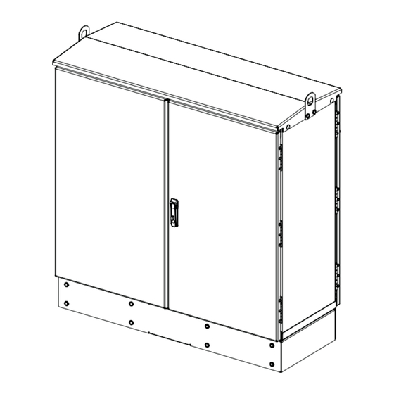
ADCP-96-135 • Rev B • January 2020 1 DESCRIPTION This section provides a description of the FDH 3000 864 cross-connect cabinet plus the cabinet specifications. 864 Cross-Connect Cabinet The 864 cross-connect cabinet is a secure, above-ground, outdoor fiber optic cabinet that provides cross-connect capability within Fiber To The Premises (FTTP) optical networks. - Page 8 49 x 48 x 20 x inches (124.5 x 121.9 x 50.8 cm) Weight (fully loaded) 500 lbs (227 kg) Certification GR-3125-CORE Connector panels (maximum) Optical ports Up to 864 with twelve 72-port connector panels Optical port adapters/connectors UPC/SC or APC/SC, Network cable lengths 100 ft. Page 2 © 2020, CommScope, Inc.
- Page 9 ADCP-96-135 • Rev B • January 2020 19.58 IN (49.7 CM) 42.53 IN 48.74 IN (108.0 CM) (123.8 CM) 47.39 IN 16.68 IN 21604-A (120.4 CM) (42.37 CM) Figure 2. 864 Cross-Connect Cabinet Dimensions Page 3 © 2020, CommScope, Inc.
-
Page 10: Before Starting The Installation
1. Open the shipping carton(s) and carefully unpack the cabinet and any accessories from the protective packing material. 2. Open the cabinet doors (requires 216B key tool) and check for broken or missing parts. If there are damages, contact CommScope using the following URL: http://www.commscope.com/SupportCenter Page 4... -
Page 11: Cabinet Installation Hardware
• Splicing equipment for splicing OSP network cables • Lifting equipment for hoisting the cabinet into position for mounting • Level • Excavation and earth moving equipment • Landscaping equipment and site restoration supplies Page 5 © 2020, CommScope, Inc. -
Page 12: Cabinet Mounting
• Utility wire (to secure PMF during installation) • Saw • Drill with screwdriver bits • Square Cabinet Mounting The next two sections provide installation instructions for the two cabinet mounting systems. Use whichever procedure is appropriate for the installation. Page 6 © 2020, CommScope, Inc. -
Page 13: Mounting The Cabinet On A Mounting Sleeve
FMS and the cabinet mounted on it. There must be room for 12 inches (30.5 cm) of fill below and on each side of the FMS. The excavation dimensions for the FMS are shown in Figure Excavate a rectangular hole for the FMS. Page 7 © 2020, CommScope, Inc. -
Page 14: Placement Of The Fms
Note: Use crushed rock 3/8-inch or less in size mixed with stone dust (per local practice) to fill the hole. The name of the material may differ in different geographical areas. Possible names are Class 5, stone dust, aughts (0s) and ones (1s), or stone aggregate Page 8 © 2020, CommScope, Inc. -
Page 15: Cable Conduit Installation
Warning: Use appropriate lifting equipment when moving or installing the cabinet. Do not stand under a cabinet as it is being hoisted into position for mounting. A failure of the lifting equipment could result in serious personal injury. Page 9 © 2020, CommScope, Inc. - Page 16 GROUND SPACER (ACCESSORY) CAPSCREWS (8), FMS SLEEVE LOCK WASHERS (8), COVER FLAT WASHERS (8) ISOLATION GASKET GROUNDING WIRE FMS ADAPTER COVER NETWORK CABLES 22530-A Figure 5. Mounting the 864 Cross-Connect Cabinet on the FMS Page 10 © 2020, CommScope, Inc.
- Page 17 Note: Label or tag the stub end of each cable so it can be identified after it is routed to the splice enclosure. 9. Carefully route the stubbed network cables through the rectangular opening in the ground spacer/riser or adapter cover and into the FMS. Page 11 © 2020, CommScope, Inc.
-
Page 18: Grounding Wire Connection To Cabinet
5. Tighten the grounding lug set screw to 30 to 35 lbs force – inches (3.4 to 4.0 Nm of torque). 6. Leave sufficient slack so the grounding wire can be routed and repositioned as needed. Page 12 © 2020, CommScope, Inc. - Page 19 ADCP-96-135 • Rev B • January 2020 CABINET GROUNDING LUG (#6 - #14 AWG WIRE) 21639-D GROUNDING WIRE ENTRY POINT GROUNDING WIRE ROUTED TO GROUNDING BUS BAR Figure 7. Grounding Wire Connection To Grounding Bus Bar Page 13 © 2020, CommScope, Inc.
-
Page 20: Mounting The Cabinet On A Concrete Pad
PMF opening at the indicated point. When installed, the top of the conduit should be located 1 to 2 inches (2.54 to 5.08 cm) below the top of the finished concrete pad. Install the conduit before pouring the pad. Page 14 © 2020, CommScope, Inc. - Page 21 Place the template over the top of the PMF and align corner holes in the template with the center holes in the PMF as shown in Figure 10. The 4-inch holes punched in the template show the locations for the conduit within the PMF. Page 15 © 2020, CommScope, Inc.
-
Page 22: Concrete Pad Construction
6. Remove the top framing and the temporary support wires when the concrete is ready to be finished. 7. Allow concrete to cure before proceeding with the installation. Page 16 © 2020, CommScope, Inc. -
Page 23: Grounding System Installation
Note: Make sure all remnants of concrete are removed from the PMF prior to mounting the cabinet. It is not necessary to use shims to level or align the cabinet as long as the top surface of the PMF is clean and free of any installation debris. Page 17 © 2020, CommScope, Inc. - Page 24 ADCP-96-135 • Rev B • January 2020 864 TERMINATION FDH 3000 CABINET (FRONT) MOUNTING BOLTS (EIGHT PLACES) MOUNTING BOLTS GROUND SPACER (EIGHT PLACES) (OPTIONAL ACCESSORY) ISOLATION PLACE NOTCH ON GASKET REAR SIDE OF CABINET REAR GROUND CABLE CONDUIT 21715-B PAD MOUNTING...
- Page 25 11. The lifting eyes may be left in place or removed from the cabinet. To remove the lifting eyes, use a 7/32-inch hex-key to remove the lifting eye screws. Store the lifting eyes inside the cabinet and then re-install the lifting eye screws in the cabinet. Page 19 © 2020, CommScope, Inc.
-
Page 26: Grounding Wire Connection To Cabinet
3/16-inch hex-key to tighten the screws that secure the access covers to the cabinet ground spacer/riser. CABINET GROUNDING LUG (#6 - #14 AWG WIRE) 21639-D GROUNDING WIRE ENTRY POINT GROUNDING WIRE ROUTED TO GROUNDING BUS BAR Figure 14. Grounding Wire Connection To Cabinet Page 20 © 2020, CommScope, Inc. -
Page 27: Osp Cable Configuration
PORTS 361-432 22534-A REAR VIEW OF REAR VIEW OF SWING FRAME SWING FRAME (PANELS 7 - 12) (PANELS 1 - 6) CABINET CONFIGURED WITH FOUR 288-FIBER OSP CABLES Figure 15. Typical OSP Cable Configuration Page 21 © 2020, CommScope, Inc. -
Page 28: Connector Panel Installation
2. Locate the cable entry/exit hole cover that corresponds to the side of the cabinet (left or right) that will receive the connector panel. CABLE CABINET ENTRY/EXIT CENTER HOLE COVER PARTITION REAR ACCESS COVER 21638-D Figure 16. Cable Entry/Exit Hole Cover Page 22 © 2020, CommScope, Inc. - Page 29 CABLE POS 13 CABLE POS 6 Figure 17. Secure OSP Cable to Cabinet Center Partition 6. Remove the two cable clamp assemblies that correspond to the selected cable clamping position from the cabinet center partition. Page 23 © 2020, CommScope, Inc.
- Page 30 Note: The push pins install in the corners of the panel and are used to hold the panel in place within the swing frame prior to installing the mounting screws. Each panel is V- shaped and one push pin is provided for each corner. Page 24 © 2020, CommScope, Inc.
- Page 31 14. Working from the front of the swing frame, use the four screws provided to secure the front of the connector panel to the swing frame as shown in Figure SCREW LOCATIONS FOR PANEL 12 (4 PLACES) 22537-B Figure 20. Secure Connector Panel to Front Side of Swing Frame Page 25 © 2020, CommScope, Inc.
- Page 32 18. If a grounding stud is provided on the cable, connect a #6 AWG jumper cable (provided with panel) to the cable grounding stud. Page 26 © 2020, CommScope, Inc.
- Page 33 (see Figure 17). The holes for the grounding cables are numbered 1–14 starting with the top opening in the weather-seal strip. Page 27 © 2020, CommScope, Inc.
- Page 34 Failure to properly tighten the nut on each individual cable grounding stud could result in improper grounding of the cable and result in performance or safety issues. 25. Close the cable grounding system access door and secure using the 216B tool. Page 28 © 2020, CommScope, Inc.
- Page 35 TIGHTEN TO 30 TO 35 21823-A LBS FORCE - INCHES (3.4 TO 4.0 Nm) OF TORQUE LEFT BUS BAR RIGHT BUS BAR CABLE ASSEMBLY CABLE ASSEMBLY Figure 24. Cable Grounding System - Exterior View Page 29 © 2020, CommScope, Inc.
-
Page 36: Routing And Connecting The Jumper Patch Cords
4. Route the jumper patch cord and store the excess slack as shown in Figure 25 (panels on same side of cabinet) or Figure 26 (panels on opposite side of cabinet). 22529-A Figure 25. Routing Jumper Patch Cords - Connector Panels on Same Side of Cabinet Page 30 © 2020, CommScope, Inc. - Page 37 ADCP-96-135 • Rev B • January 2020 22533-A Figure 26. Routing Jumper Patch Cords - Connector Panels on Opposite Sides of Cabinet Page 31 © 2020, CommScope, Inc.
-
Page 38: Maintenance And Repair Procedures
FROM THE ADAPTER, INSTALL A DUST CAP ON THE CONNECTOR TO KEEP THE ENDFACE CLEAN AND TO PREVENT DAMAGE METAL TAB (TOP AND BOTTOM) PATCH CORD 22538-A ADAPTER CONNECTOR Figure 27. Adapter Removal and Replacement Page 32 © 2020, CommScope, Inc. -
Page 39: Replacing A Damaged Fiber Or Connector
3. Clean both connectors as specified in the Optical Fiber Connector Wet and Dry Cleaning Instructions (ADCP-90-159) or by locally approved procedures. 4. Reconnect the good connector and the replacement connector to the adapter. Page 33 © 2020, CommScope, Inc. -
Page 40: Door Gasket Replacement
Figure 29. Save the nuts and washers for reuse. GROUNDING GROUNDING STRAP LUG STRAP LUG DOOR DOOR HINGES HINGES 22535-A DOOR BRACKET DOOR BRACKET SLIDE SLIDE Figure 28. Door Replacement Page 34 © 2020, CommScope, Inc. -
Page 41: Grounding System Terminal Access Procedure
1. Locate the small hinged access cover on the side of the cabinet as shown in Figure 2. Use the 216B tool to remove the screw that secures the access cover in the closed position. Page 35 © 2020, CommScope, Inc. - Page 42 Failure to properly tighten the nut on each individual cable grounding stud could result in improper grounding of the cable and result in performance or safety issues. 8. Close and secure grounding block access cover. Page 36 © 2020, CommScope, Inc.
- Page 43 ADCP-96-135 • Rev B • January 2020 9 CUSTOMER INFORMATION AND ASSISTANCE Visit our website or contact your local CommScope representative for more information. ® • To find out more about CommScope products, visit us on the web at www.commscope.com •...
Need help?
Do you have a question about the FDH 3000 and is the answer not in the manual?
Questions and answers