
Subscribe to Our Youtube Channel
Related Manuals for CommScope Ruckus ICX 7750


Summary of Contents for CommScope Ruckus ICX 7750
- Page 1 HARDWARE INSTALLATION GUIDE RUCKUS ICX 7750 Switch Hardware Installation Guide Part Number: 53-1003900-10 Publication Date: 30 September 2020...
- Page 2 CommScope, Inc. and/or its affiliates (“CommScope”). CommScope reserves the right to revise or change this content from time to time without obligation on the part of CommScope to provide notification of such revision or change.
-
Page 3: Table Of Contents
............. 14 Ruckus ICX 7750 slot and Ethernet port numbering . - Page 4 ................64 Replacing a power supply Ruckus ICX 7750 Switch Hardware Installation Guide Part Number: 53-1003900-10...
- Page 5 BSMI statement (Taiwan) Ruckus ICX 7750 Cautions and Danger Notices ....................83 Cautions .
- Page 6 Ruckus ICX 7750 Switch Hardware Installation Guide Part Number: 53-1003900-10...
-
Page 7: Preface
Safety labels are also attached directly to products to warn of these conditions or situations. Command syntax conventions Bold and italic text identify command syntax components. Delimiters and operators define groupings of parameters and their logical relationships. Ruckus ICX 7750 Switch Hardware Installation Guide Part Number: 53-1003900-10... -
Page 8: Document Feedback
Access to Release Notes requires an active support contract and Ruckus Support Portal user account. Other technical documentation content is available without logging into the Ruckus Support Portal. White papers, data sheets, and other product documentation are available at https://www.ruckuswireless.com. Ruckus ICX 7750 Switch Hardware Installation Guide Part Number: 53-1003900-10... -
Page 9: Online Training Resources
Ruckus products, including: • Technical Documentation—https://support.ruckuswireless.com/documents • Community Forums—https://forums.ruckuswireless.com/ruckuswireless/categories • Knowledge Base Articles—https://support.ruckuswireless.com/answers • Software Downloads and Release Notes—https://support.ruckuswireless.com/software • Security Bulletins—https://support.ruckuswireless.com/security Ruckus ICX 7750 Switch Hardware Installation Guide Part Number: 53-1003900-10... - Page 10 Using these resources will help you to resolve some issues, and will provide TAC with additional data from your troubleshooting analysis if you still require assistance through a support case or RMA. If you still require help, open and manage your case at https:// support.ruckuswireless.com/case_management Ruckus ICX 7750 Switch Hardware Installation Guide Part Number: 53-1003900-10...
-
Page 11: About This Document What's New In This Document
Described in 10G-SFPP-TX transceiver support Added guidelines for using the 10G-SFPP-TX “10G-SFPP-TX-A transceiver support” transceiver Power and cooling Added information on fan speeds and temperature “Monitoring power and cooling” thresholds Ruckus ICX 7750 Switch Hardware Installation Guide Part Number: 53-1003900-10... - Page 12 About this Document What’s new in this document Ruckus ICX 7750 Switch Hardware Installation Guide Part Number: 53-1003900-10...
-
Page 13: Ruckus Icx 7750 Overview
(must be ordered separately). Advanced software. No optics. Ruckus ICX 7750 customizable models The Ruckus ICX 7750 base systems do not ship with power supplies or fans. Fans and power supplies are ordered separately to allow for building the system that meets your network needs. -
Page 14: Views Of The Ruckus Icx 7750 Switch
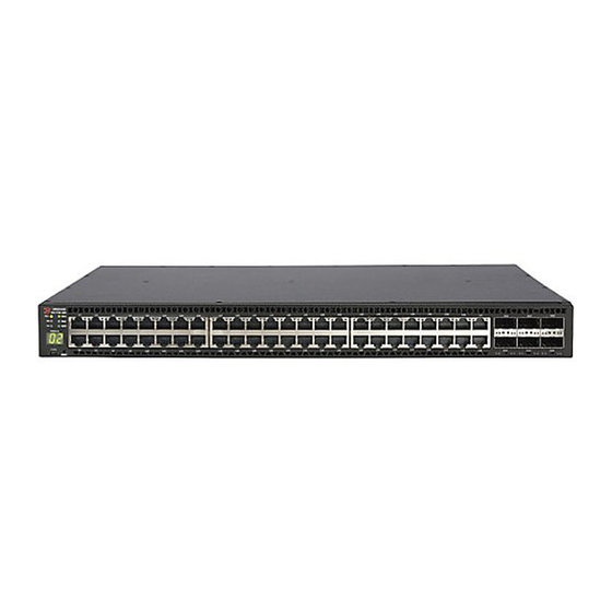
Ruckus ICX 7750 6-port QSFP+ expansion/stacking module. Views of the Ruckus ICX 7750 switch Figure 1 shows the front view of the Ruckus ICX 7750-26Q switch. FIGURE 1 Front view of the Ruckus ICX 7750-26Q QSFP+ ports XL1/1 - XL1/20 and XL2/1 -... - Page 15 System LEDs SFP+ port LEDs Stack unit ID display QSFP+ port LEDs Figure 3 shows the front view of the Ruckus ICX 7750-48C switch. FIGURE 3 Front view of the Ruckus ICX 7750-48C 10GBase-T RJ-45 ports 1/1 - 1/48 Console port...
-
Page 16: Ruckus Icx 7750 Slot And Ethernet Port Numbering
• Slot 1 and Slot 2 are located on the front of the Ruckus ICX 7750-26Q device. Slot 1 contains 10/40 GbE QSFP+ ports XL1/1 through XL1/20; odd port numbers on the top row with port XL1/1 on the left and port XL1/20 on the right. Slot 2 contains 10/40 GbE QSFP+ ports XL2/1 through XL2/6;... -
Page 17: Supported Expansion Module
• Slot 3 is located on the rear of the Ruckus ICX 7750 switches and contains ports XL3/1, XL3/3, and XL3/5 on the top row (left to right) and ports XL3/2, XL3/4, and XL3/6 on the bottom row (left to right). These ports are 10/40 GbE QSFP+ ports. -
Page 18: Supported Transceivers And Cables
1/3/5 and 1/3/6 The Ruckus ICX 7750 also supports 40GBASE-SR-BD bi-directional (BiDi) QSFP+ transceivers with duplex LC optics. The 40 GbE BiDi optics support two 20 GbE channels over duplex fiber cable, with the transmit and receive of each channel operating at two wavelengths on a single fiber. -
Page 19: Breakout Cables
1/3/1 through 1/3/6 QSFP+ to SFP+ adapter support The Ruckus ICX 7750 supports a third-party QSFP+ to SFP+ adapter for cost-effective connections between 40 GbE QSFP+ ports and 10 GbE hardware using standard SFP+ optical cabling rather than breakout cables. - Page 20 Ruckus ICX 7750 10G-SFPP-TX-A transceiver support Model 10G-SFPP-TX-A installed For each 10G-SFPP-TX-A inserted, this location many SFP+ ports must remain unused. ICX 7750-48F Port Group #1 1/1/1 to 1/1/32 Port Group ~2 1/1/33 to 1/1/48 Ruckus ICX 7750 Switch Hardware Installation Guide Part Number: 53-1003900-10...
-
Page 21: Installing The Ruckus Icx 7750
Shipping carton contents Ruckus ICX 7750 devices ship with all of the following items included in the shipping carton. When unpacking the device, verify that the contents of the shipping carton is complete, if any items are missing, contact the place of purchase. -
Page 22: Installation And Safety Considerations
• Because the Ruckus ICX 7750 can be ordered with fans that move air either front to back or back to front, be sure to orient your switch with the airflow pattern of any other devices in the rack. All equipment in the rack should force air in the same direction to avoid intake of exhaust air. -
Page 23: Rack Considerations
Ensure that the physical environment that will host the device has the proper “Installation and safety considerations” on page 20 cabling and ventilation. If customizing a Ruckus ICX 7750 baseline chassis: “Installing and replacing a power supply unit” page 38 Install at least one power supply unit. -
Page 24: Installation Precautions
Make sure the airflow around the front and sides of the device is not restricted. CAUTION Never leave tools inside the device. DANGER Risk of explosion if battery is replaced by an incorrect type. Dispose of used batteries according to the manufacturer’s instructions. Ruckus ICX 7750 Switch Hardware Installation Guide Part Number: 53-1003900-10... -
Page 25: Lifting Precautions
For the DC input circuit to the system, make sure there is a 20 Amp circuit breaker, minimum 60 VDC, double pole, on the input terminal block to the power supply. The input wiring for connection to the product should be copper wire, 12 AWG, marked VW-1, and rated minimum 90°C. Ruckus ICX 7750 Switch Hardware Installation Guide Part Number: 53-1003900-10... -
Page 26: Installing The Device In A Rack
“Installing the 1U, 1.5U, and 2U Universal Kit for Four-Post Racks (XBR-R000295)” on page 26. Two-post rack mount installation The Ruckus ICX 7750 can be installed in a two-post rack in various mounting positions, as shown in Figure FIGURE 11 Two-post rack mounting positions... - Page 27 NOTE Use the following procedure when installing the Ruckus ICX 7750 in a two-post Telco rack only. If an ICX 7750 device is to be installed into a standard four-post rack, make sure that the correct rack mount kit has been purchased. For four-post racks, follow the procedures in “Installing the 1U, 1.5U, and 2U Universal Kit for Four-Post Racks (XBR-R000295)”...
-
Page 28: Installing The 1U, 1.5U, And 2U Universal Kit For Four-Post Racks (Xbr-R000295)
Installing the Ruckus ICX 7750 Installing the 1U, 1.5U, and 2U Universal Kit for Four-Post Racks (XBR-R000295) FIGURE 13 Installing the Ruckus ICX 7750 in a 2-post rack Proceed to “Grounding the system” on page 37. Installing the 1U, 1.5U, and 2U Universal Kit for Four-Post Racks (XBR-R000295) Use the following instructions to install a 1U, 1.5U, or 2U device in a 19-in. -
Page 29: Parts List
Rear brackets, long (2) 10 Retainer nut, 10-32 (8) Flush-front mounting the device in the rack CAUTION The device must be turned off and disconnected from the fabric during this procedure. Ruckus ICX 7750 Switch Hardware Installation Guide Part Number: 53-1003900-10... - Page 30 Repeat Step 1 and Step 2 to attach the left front bracket to the left side of the device. Tighten all the 8-32 x 5/16-in. screws to a torque of 15 in-lb (17 cm-kg). FIGURE 15 Attaching the front brackets Ruckus ICX 7750 Switch Hardware Installation Guide Part Number: 53-1003900-10...
- Page 31 Attach the right front bracket to the right front rack post using two 10-32 x 5/8-in. panhead screws and two retainer nuts. Use the upper and lower holes in the bracket. Ruckus ICX 7750 Switch Hardware Installation Guide Part Number: 53-1003900-10...
- Page 32 Repeat step 2 and step 3 to attach the left rear bracket to the left extension. Adjust the brackets to the rack depth and tighten all the 6-32 x 1/4-in. screws to a torque of 9 in-lb (10 cm-kg). Ruckus ICX 7750 Switch Hardware Installation Guide Part Number: 53-1003900-10...
- Page 33 Attach the left rear bracket to the left rear rack post using two 10-32 x 5/8-in. panhead screws and two retainer nuts. Use the upper and lower holes in the bracket. Tighten all the 10-32 x 5/8-in. screws to a torque of 25 in-lb (29 cm-kg). Ruckus ICX 7750 Switch Hardware Installation Guide Part Number: 53-1003900-10...
-
Page 34: Flush-Rear (Recessed) Mounting The Device In The Rack
34 “Attaching the rear brackets to the extensions at the front of the device” on page 35 “Attaching the rear brackets to the front rack posts” on page 36 Ruckus ICX 7750 Switch Hardware Installation Guide Part Number: 53-1003900-10... - Page 35 Select the proper length extension bracket for your rack depth. Position the right extension along the side of the device as shown in Figure Attach the bracket using four 8-32 x 5/16-in. flathead screws. Ruckus ICX 7750 Switch Hardware Installation Guide Part Number: 53-1003900-10...
- Page 36 Attach the left front bracket to the left rear rack post using two 10-32 x 5/8-in. panhead screws and two retainer nuts. Use the upper and lower holes in the bracket. Tighten all the 10-32 x 5/8-in. screws to a torque of 25 in-lb (29 cm-kg). Ruckus ICX 7750 Switch Hardware Installation Guide Part Number: 53-1003900-10...
- Page 37 Repeat Step 2 and Step 3 to attach the left rear bracket to the left extension. Adjust the brackets to the rack depth and tighten all the 6-32 x 1/4-in. screws to a torque of 9 in-lb (10 cm-kg). Ruckus ICX 7750 Switch Hardware Installation Guide Part Number: 53-1003900-10...
- Page 38 Attach the left rear bracket to the left front rack post using two 10-32 x 5/8-in. screws and two retainer nuts. Use the upper and lower holes in the bracket. Ruckus ICX 7750 Switch Hardware Installation Guide Part Number: 53-1003900-10...
-
Page 39: Grounding The System
Grounding the system The rear panel of the Ruckus ICX 7750 includes a single-screw grounding terminal. The surface area around this terminal is not painted to provide a good electrical connection. Before connecting power to the device, the grounding terminal must be connected to ground to ensure proper operation and to meet electromagnetic interference (EMI) and safety requirements. -
Page 40: Powering On The System
Crimp the included grounding lug to a grounding wire of at least 6 American Wire Gauge (AWG). The 6 AWG wire and grounding lug should be crimped together using a proper tool. Attach the 6 AWG stranded copper wire to the grounding terminal on the Ruckus ICX 7750 using the screw included in the grouding kit. -
Page 41: Installing An Ac Power Supply
CAUTION For Ruckus ICX 7750 devices, be sure that the airflow direction of the power supply unit matches that of installed fan trays. The power supplies and fan trays are clearly labeled with either a green arrow with an “E”, or an orange arrow with an “I.”... -
Page 42: Installing A Dc Power Supply
When you are sure the power supply has properly engaged the connector, tighten the retainer screws to secure the power supply in the slot. When the Ruckus ICX 7750 is powered on, the LEDs on the power supply rear panel should light up green to confirm that the power supply is correctly installed and supplying power. -
Page 43: Attaching A Pc Or Terminal
When you are sure the power supply has properly engaged the connector, tighten the chassis attachment screws to secure the power supply in the slot. When the Ruckus ICX 7750 is powered on, the power LED on the front of the device should turn green to confirm that the power supply is correctly installed and supplying power. Refer to “Ruckus ICX 7750 front-panel LEDs”... -
Page 44: Connecting To The Management Port
The Gigabit Ethernet management port (RJ-45) on the Ruckus ICX 7750 rear panel provides an out-of-band network connection to the device. After you assign an IP address, you can access the Ruckus ICX 7750 from anywhere in the attached network using Telnet, a web browser, or other network management tools, such as Ruckus Network Advisor. -
Page 45: Connecting Network Devices
Connecting network devices NOTE When 10 GbE fiber-optic ports on the Ruckus ICX 7750 are disabled, the laser light remains on even though the port link is down. Use the following steps to install a transceiver: Put on the ESD wrist strap and ground yourself by attaching the clip end to a metal surface (such as an equipment rack) to act as ground. -
Page 46: Connecting A Network Device To A Copper Port
51. NOTE To verify that a Ruckus ICX 7750 can reach another device through the network, use the ping command at any level of the CLI. For more information, refer to the Ruckus FastIron Management Configuration Guide. Cleaning the fiber-optic connectors To avoid problems with the connection between the fiber-optic transceiver (SFP+ or QSFP+) and the fiber cable connectors, Ruckus strongly recommends cleaning both connectors each time you disconnect and reconnect them. -
Page 47: Connecting Breakout Cables To 40 Gbe Ports
Stacking Ruckus ICX 7750 switches Connecting breakout cables to 40 GbE ports A 40 GbE breakout cable can only be used on standalone Ruckus ICX 7750 devices to break out certain 40 GbE QSFP+ ports into four 10 GbE sub-ports. (Refer to “Breakout cables”... -
Page 48: Stacking Configuration Requirements
Unused stacking ports can be used as data ports. For example, you can elect to use only one default port as a stacking port and use the other default port as a data port. Furthermore, when a Ruckus ICX 7750-6Q stacking module is not configured for stacking, its ports can be used as data ports. -
Page 49: Stacking Cables
10 kilometers for ICX 7750-26Q device only Stack size The Ruckus ICX 7750 supports up to 12 units in a stack. You can mix any number of Ruckus ICX 7750-26Q, Ruckus ICX 7750-48F, or Ruckus ICX 7750-48C devices together in a stack. - Page 50 FIGURE 35 Rear panel ring stacking topology Figure 36 shows a supported front panel ring stacking topology. FIGURE 36 Front panel ring stacking topology Ruckus ICX 7750 Switch Hardware Installation Guide Part Number: 53-1003900-10...
- Page 51 Figure 37 shows a supported rear panel ring trunk-stack topology. FIGURE 37 Rear panel ring trunk-stack topology NOTE For more information about stacking, refer to the Ruckus FastIron Stacking Configuration Guide. Ruckus ICX 7750 Switch Hardware Installation Guide Part Number: 53-1003900-10...
- Page 52 Installing the Ruckus ICX 7750 Stacking Ruckus ICX 7750 switches Ruckus ICX 7750 Switch Hardware Installation Guide Part Number: 53-1003900-10...
-
Page 53: Ruckus Icx 7750 Operation
LEDs do not indicate a healthy state after all boot processes and diagnostic tests are complete. Ruckus ICX 7750 front-panel LEDs The Ruckus ICX 7750-26Q has the following LEDs on the front panel: • Two power supply unit (PSU) bicolor status LEDs (green and amber) labeled PSU1 and PSU2 •... - Page 54 4x10 GbE breakout mode Figure 39 shows the LEDs on the Ruckus ICX 7750-48C front panel. The up-arrow port status LEDs for the 1/10 GbE ports correspond to the upper, odd-numbered ports; the down-arrow port status LEDs correspond to the lower, even-numbered ports.
- Page 55 PSU2 corresponds to the left power supply slot, as viewed from the rear) The Ruckus ICX 7750-48F has the following LEDs on the front panel: • Two power supply unit (PSU) bicolor status LEDs (green and amber) labeled PSU1 and PSU2 •...
-
Page 56: Ruckus Icx 7750 Rear-Panel Leds
PSU2 corresponds to the left power supply slot, as viewed from the rear) Ruckus ICX 7750 rear-panel LEDs The Ruckus ICX 7750 has the following LEDs on the rear panel: • Two Management port status LEDs •... -
Page 57: Led Patterns
LEDs Upper slot 10 GbE mode lanes 2, 3, and 4 Expansion module power LED link/activity LEDs LED patterns The following tables describe the Ruckus ICX 7750 LED patterns. TABLE 10 PSU1 and PSU2 LEDs LED state Status of hardware... - Page 58 Steady amber Link is up in 1 GbE mode. No action required. Blinking amber There is 1 GbE traffic and packets are being transmitted or No action required. received. Ruckus ICX 7750 Switch Hardware Installation Guide Part Number: 53-1003900-10...
- Page 59 Module is on and booting up. No action required. TABLE 23 Fan tray LED LED state Status of hardware Recommended action Off (no light) Fan tray is not powered on. No action required. Ruckus ICX 7750 Switch Hardware Installation Guide Part Number: 53-1003900-10...
-
Page 60: Diagnostic Tests And Monitoring
If the switch reaches or exceeds the critical (shutdown) temperature for two minutes, the switch shuts down. Ruckus ICX 7750 Switch Hardware Installation Guide Part Number: 53-1003900-10... - Page 61 Current temperature : 31.0 deg-C Right Front Temperature Readings: Current temperature : 28.0 deg-C Warning level..: 50.0 deg-C Shutdown level..: 81.0 deg-C Boot Prom MAC : 609c.9fd7.bd80 Management MAC: 609c.9fd7.bd80 ICX7750-26Q Router# Ruckus ICX 7750 Switch Hardware Installation Guide Part Number: 53-1003900-10...
- Page 62 Ruckus ICX 7750 Operation Monitoring power and cooling Ruckus ICX 7750 Switch Hardware Installation Guide Part Number: 53-1003900-10...
-
Page 63: Managing The Ruckus Icx 7750
Replacing a copper or fiber-optic module You can remove an SFP+, or QSFP+ transceiver from a slot and replace it with a new one while the Ruckus ICX 7750 is powered on and running. -
Page 64: Cabling A Fiber-Optic Module
FRU removal and replacement procedures NOTE When 10 GbE fiber-optic ports on the Ruckus ICX 7750 are disabled, the laser light remains on even though the port link is down. To remove a copper or fiber-optic module from a transceiver slot, do the following. -
Page 65: Replacing A Power Supply Unit
CAUTION For the Ruckus ICX 7750 devices, be sure that the airflow direction of the power supply unit matches that of the installed fan tray. The power supplies and fan trays are clearly labeled with either a green arrow with an “E”, or an orange arrow with an “I.”... -
Page 66: Determining The Need To Replace A Power Supply
Complete the following steps to replace a power supply in a Ruckus ICX 7750. To leave the Ruckus ICX 7750 in service while replacing a power supply, verify that the other power supply (the one not being replaced) has been powered on for at least four seconds and has a steady green status LED. -
Page 67: Replacing Fan Trays
The power supply will immediately attempt to power up. 11. Verify that the LED on the new power supply displays steady green while the Ruckus ICX 7750 is operating. If the LED is not steady green, ensure that the power supply is securely installed and seated properly. Alternatively, check the PSU1 and PSU2 LEDs on the switch front panel (refer to “LED patterns”... -
Page 68: Replacing An Expansion Module
Replacing an expansion module The Ruckus ICX 7750 includes a rear-panel slot for a 6-port QSFP+ 40 GbE expansion module. If not installed, the empty expansion module slot must be covered using the filler panel. CAUTION Disassembling any part of the expansion module voids the warranty and regulatory certifications. -
Page 69: Installing Or Replacing An Expansion Module
NOTE The Ruckus ICX 7750 must be powered off before installing or replacing an expansion module. Complete the following steps to install or replace an expansion module in the Ruckus ICX 7750. If replacing an expansion module: Pull the release latch lever on the module into its open position. - Page 70 Managing the Ruckus ICX 7750 Replacing an expansion module Ruckus ICX 7750 Switch Hardware Installation Guide Part Number: 53-1003900-10...
-
Page 71: Ruckus Lrm Adaptor Module
10G LRM SFP+ Optic, 1-pack bundle with LRM adapter. Includes rack mount bracket 10G-SFPP-LRM-2-ADP 10G LRM SFP+ Optic, 2-pack bundle with LRM adapter. Includes rack mount bracket RMK-LRM-ADP 19-inch LRM Adapter Rack Mount Shelf Kit (supports 8 units) Ruckus ICX 7750 Switch Hardware Installation Guide Part Number: 53-1003900-10... -
Page 72: Lrm Adaptor Module Specifications
When unpacking the LRM adaptor, verify that the contents of the shipping carton is complete. Save the shipping carton and packaging in the event you need to return the shipment. • One LRM adaptor • One or two L-shaped mounting brackets (depending on the model purchased) Ruckus ICX 7750 Switch Hardware Installation Guide Part Number: 53-1003900-10... - Page 73 Ruckus LRM Adaptor Module Unpacking the LRM module • One or two 10G-SFPP-LRM optics (depending on the model purchased) • China-RoHS Hazardous/Toxic Substance statement Ruckus ICX 7750 Switch Hardware Installation Guide Part Number: 53-1003900-10...
- Page 74 Ruckus LRM Adaptor Module Unpacking the LRM module Ruckus ICX 7750 Switch Hardware Installation Guide Part Number: 53-1003900-10...
-
Page 75: System Specifications
ICX 7750-48C: 48 1/10 GbE RJ-45 ports and six 10/40 GbE QSFP+ ports System processors System processor 1.5 GHz Freescale P2041 Ethernet System component Description SFP GbE ports 40/10/1 GbE optical and copper Ethernet management port Ruckus ICX 7750 Switch Hardware Installation Guide Part Number: 53-1003900-10... -
Page 76: Leds
Shock 20 G, 11 ms, half-sine wave 30 G, 11 ms, half-sine wave Vibration 1 G sine, 0.4 grms random, 5-500 Hz 2.4 G sine, 1.12 grms random, 5-500 Hz Ruckus ICX 7750 Switch Hardware Installation Guide Part Number: 53-1003900-10... -
Page 77: Power Supply Specifications (Per Psu)
Fan speed is at nominal. 867 BTU/hr 853 BTU/hr 853 BTU/h ICX 7750-48C 510 W 511 W 511 W 1 AC or DC Fan speed is at nominal. 1740 BTU/hr 1744 BTU/hr 1744 BTU/hr Ruckus ICX 7750 Switch Hardware Installation Guide Part Number: 53-1003900-10... -
Page 78: Power Consumption (Maximum Configuration)
10GBASE-T, 1/10 Gbps, capable of auto-negotiating link speed. Serial port specifications (pinout mini-USB) Signal Description Reserved Not used UART0_RX Data received by ICX UART0_TX Data transmitted by ICX Reserved Not used Ground Ruckus ICX 7750 Switch Hardware Installation Guide Part Number: 53-1003900-10... -
Page 79: Serial Port Specifications (Pinout Rj-45)
EN 55024 (CE mark) (Immunity) for Information Technology Equipment • ICES-003 (Canada) (Class A) • AS/NZ 55022 (Australia) (Class A) • VCCI (Japan) (Class A) • EN 61000-3-2 • EN 61000-3-3 • EN 61000-6-1 Ruckus ICX 7750 Switch Hardware Installation Guide Part Number: 53-1003900-10... -
Page 80: Regulatory Compliance (Safety)
SJ/T 11363-2006 Requirements for Concentration Limits for Certain Hazardous Substances in EIPs (China) • SJ/T 11364-2006 Marking for the Control of Pollution Caused by EIPs (China) • CNS 15663 (BSMI) (Taiwan) Ruckus ICX 7750 Switch Hardware Installation Guide Part Number: 53-1003900-10... -
Page 81: Usa (Fcc Cfr 47 Part 15 Warning)
This is a Class A product. In a domestic environment this product may cause radio interference in which case the user may be required to take adequate measures. Germany (Noise Warning) Maschinenlärminformations-Verordnung - 3. GPSGV, der höchste Schalldruckpegel beträgt 53.0 dB(A) gemäss EN ISO 7779. English translation of above statement Ruckus ICX 7750 Switch Hardware Installation Guide Part Number: 53-1003900-10... -
Page 82: Japan (Vcci)
Class A device (Broadcasting Communication Device for Office Use): This device obtained EMC registration for office use (Class A), and may be used in places other than home. Sellers and/or users need to take note of this. Ruckus ICX 7750 Switch Hardware Installation Guide Part Number: 53-1003900-10... -
Page 83: China
English translation of above statement This is a Class A product. In a domestic environment this product may cause radio interference, inwhich case the user may be required to take adequate measures. Ruckus ICX 7750 Switch Hardware Installation Guide Part Number: 53-1003900-10... -
Page 84: Bsmi Statement (Taiwan)
Note 2 “ ” indicates that the percentage content of the restricted substance does not exceed the percentage of reference value of presence. Note 3 The “−” indicates that the restricted substance corresponds to the exemption. Ruckus ICX 7750 Switch Hardware Installation Guide Part Number: 53-1003900-10... -
Page 85: Ruckus Icx 7750 Cautions And Danger Notices
CAUTION All devices with DC power supplies (Ruckus ICX 7750 ) are intended for installation in restricted access areas only. A restricted access area is where access can be gained only by service personnel through the use of a special tool, lock and key, or other means of security, and is controlled by the authority responsible for the location. - Page 86 Ruckus ICX 7750 Cautions and Danger Notices Cautions CAUTION Make sure the airflow around the front, sides, and back of the device is not restricted. VORSICHT Stellen Sie sicher, dass an der Vorderseite, den Seiten und an der Rückseite der Luftstrom nicht behindert wird.
- Page 87 Ruckus ICX 7750 Cautions and Danger Notices Cautions CAUTION Remove the power cord from a power supply before you install it in or remove it from the device. Otherwise, the power supply or the device could be damaged as a result. (The device can be running while a power supply is being installed or removed, but the power supply itself should not be connected to a power source.)
- Page 88 CAUTION For the DC input circuit to the system of a Ruckus ICX 7750, make sure there is a UL-Listed 20 Amp circuit breaker, minimum 60 VDC, double pole, on the input lugs to the power supply. The input wiring for connection to the product should be Listed copper wire, 12 AWG, marked VW-1, and rated minimum 90°C.
-
Page 89: Danger Notices
Ruckus ICX 7750 Cautions and Danger Notices Danger notices Danger notices A danger notification calls your attention to a possible hazard that can cause injury or death. The following are the warnings used in this manual. "Gefahr" weist auf eine mögliche Gefährdung hin, die zu Verletzungen oder Tod führen können. Sie finden die folgenden Warnhinweise in diesem Handbuch. - Page 90 Ruckus ICX 7750 Cautions and Danger Notices Danger notices DANGER If the installation requires a different power cord than the one supplied with the device, make sure you use a power cord displaying the mark of the safety agency that defines the regulations for power cords in your country. The mark is your assurance that the power cord can be used safely with the device.
- Page 91 © 2020 CommScope, Inc. All rights reserved. Ruckus Wireless, Inc., a wholly owned subsidiary of CommScope, Inc. 350 West Java Dr., Sunnyvale, CA 94089 USA www.ruckuswireless.com...
Need help?
Do you have a question about the Ruckus ICX 7750 and is the answer not in the manual?
Questions and answers