Table of Contents
Advertisement
Quick Links
860576982
Issue 5, September 2015
www.commscope.com
General
®
The Redwood
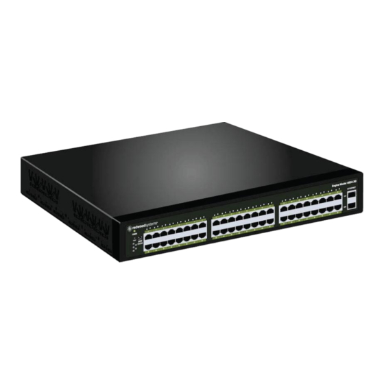
Engine 3 Model 4834 powers and communicates with Redwood gateways, sensors, and wall
switches
to provide intelligent lighting control and building intelligence. The engine provides a sophisticated level of
control w h i c h significantly reduces energy consumption. Multiple engines can be linked together to power and
control hundreds or thousands of fixtures.
The engine provides communications and control for all types of lighting including LED, fluorescent, CFL and HID.
In the case of LED lighting, the engine also provides centralized AC to DC power conversion. It takes high voltage
200–250 VAC or 277 VAC input power, converts it to low-voltage DC, and distributes the power to all fixtures via
Redwood LED sensors and gateways using Class 2, low-voltage cabling. The engine can be located on a rack or
wall mounted in an electrical or telecom closet.
Ordering information is listed below:
Part No.
ENG-3-4834-250
ENG-3-4834-277
WallMount-Tray-1G
How to Contact Us
To find out more about CommScope
For technical assistance:
-
Live technical support for Redwood
8 AM to 5 PM (PST), excluding holidays.
-
Within North and South America, contact your local account representative or technical
support at 1-800-840-0709 (Option 2). Outside North and South America, contact your
local account representative or technical support at +1 510-270-5360 (Option 2).
-
An email can also be sent to RedwoodSupport@commscope.com for technical support.
Engine 3 Model 4834 Installation
Description
Engine, generation 3, 200–250 VAC
Engine, generation 3, 277 VAC
Engine wall mount kit
®
Redwood
®
products, visit us on the web at
®
products is available Monday through Friday from
© 2015 CommScope, Inc.
All rights reserved
Engine 3 Model 4834
www.commscope.com/
For RoHS Inquiries:
CommScope Inc.
Corke Abbey, Bray
Co. Dublin, Ireland
Attn: Legal Department
Page 1 of 7
Advertisement
Table of Contents

Summary of Contents for CommScope Engine 3 Model 4834
-
Page 1: How To Contact Us
General ® The Redwood Engine 3 Model 4834 powers and communicates with Redwood gateways, sensors, and wall switches to provide intelligent lighting control and building intelligence. The engine provides a sophisticated level of control w h i c h significantly reduces energy consumption. Multiple engines can be linked together to power and control hundreds or thousands of fixtures. - Page 2 860576982 www.commscope.com Instruction Sheet Separately Orderable Components Part No. Description PC-AUS-120-250 Engine power cord for Australia, New Zealand: 15A, 250 VAC, 3.6m PC-BRAZIL Engine power cord for Brazil: 10 A, 250 VAC, 2.5m PC-CHINA Engine power cord for China: 16 A, 250 VAC, 3.0m PC-DENMARK Engine power cord for Denmark: 16 A, 250 VAC, 2.5m...
- Page 3 860576982 Instruction Sheet Preparation 1. Determine location for all fixtures and Redwood dimmers. 2. Determine location for all Redwood engines. The engine is a 1.5U rack mountable system and can be installed in a standard server rack using supplied rack-mounting L brackets, or to the wall with a Redwood wall mount kit.
- Page 4 860576982 www.commscope.com Instruction Sheet Wall Mount Instructions Note: The Redwood engine can be installed flush against a wall using a Redwood wall mount kit as shown above. The wall mount kit contains two pieces, a wall mount tray and a drip pan.
- Page 5 860576982 Instruction Sheet Cabling 1. Using a conventional method, connect the category cable wiring from the gateway to the punch down side of patch panel. 2. Use an RJ45 jumper cable (or patch cable) to connect the corresponding ports from patch panel.
- Page 6 860576982 www.commscope.com Instruction Sheet For the 200 VAC–250 VAC version, the engine requires a maximum 12A of current from the branch circuit to which it is connected when operating at full power. At minimum, a 15A branch circuit is required for a single engine, given the standard 80% de-rating.
- Page 7 860576982 Instruction Sheet Port Indicator Status: Each port on the engine has a multi-color LED to communicate status for that port. After a period of inactivity, the LEDs are turned off to save energy. To activate the lights, press the Show Status button on the engine faceplate.


Need help?
Do you have a question about the Engine 3 Model 4834 and is the answer not in the manual?
Questions and answers