Table of Contents
Advertisement
Quick Links
Advertisement
Table of Contents

Related Manuals for Qualstar TLS-5000


Summary of Contents for Qualstar TLS-5000
- Page 1 TLS-5000 TLS-6000 TLS-8000 Installation and Operation Manual 501450 Rev. K...
- Page 3 This manual was revised to correspond with the firmware version indicated below. Do not use this manual with older versions of the firmware. Check with Qualstar Technical Support about use of this manual with newer firmware.
- Page 4 Qualstar products are covered by one or more of the following patents: 6,163,139 and 6,560,061. Other patents pending. Qualstar equipment is manufactured from new parts, or new and used parts. In some cases, Qualstar equipment may not be new and may have been previously installed.
- Page 5 European Directive. The effectivity date for compliance is July 1, 2006, at which time Qualstar will certify that its Tape Library products are compliant with the RoHS standard. With the exception of Lead Based Solder, Qualstar will certify that its products are free of all other substances listed in the Directive.
- Page 6 2010. Insofar as lead free solders are new to the electronics industry and no quality or reliability data is available, Qualstar will invoke the lead based solder exemption until such time as industry data verifies that lead free solders are capable of meeting or exceeding the documented reliability and quality standards achieved with lead based solders.
-
Page 7: Table Of Contents
Table of Contents Introduction........................1-1 Who Should Read This Manual ................1-1 Important Safety Information .................. 1-2 Lithium Battery ......................1-3 Class 1 LED Product ....................1-4 Unpacking ........................2-1 Unpacking Models 6110, 62xx, 8111 and 82xx ............2-1 Models 54xx, 64xx and 84xx ..................2-4 Models 58xxx, 68xxx and 88xxx................ - Page 8 Introduction........................ 4-1 Display........................4-1 Control Keys....................... 4-2 I/O Port ........................4-2 Installation ........................5-1 Installation Considerations..................5-1 5.1.1 Operating Environment ..................5-1 5.1.2 Power Requirements and Consumption .............. 5-1 5.1.3 Power Source Disturbances .................. 5-2 5.1.4 Ventilation ......................5-3 Stabilizer Feet Installation ..................5-6 Locking Casters on Dual Bay Models...............
- Page 9 6.1.3 The ENTER Control Key ..................6-2 6.1.4 The EXIT Control Key ..................6-3 6.1.5 (Daisy) Key ....................6-3 The Top Menu ......................6-5 Menu Elements ......................6-6 6.3.1 Menu Items......................6-6 6.3.2 Values........................6-7 6.3.3 Location Designators..................... 6-8 6.3.4 Editing Values .......................
- Page 10 8.4.6 Use Private Slot..................... 8-9 Configuration\Advanced\Changer\Door Lock Menu ..........8-9 Configuration\Advanced\Changer\Inventory Menu........... 8-10 8.6.1 Invalidate ......................8-11 8.6.2 Label Scan......................8-11 8.6.3 Mag. Labels......................8-11 8.6.4 PowerOn....................... 8-12 8.6.5 Seq. Labels ......................8-12 8.6.6 Source Drive ......................8-12 8.6.7 Source I/O Port ....................8-13 Configuration\Advanced\Changer\I/O Port Menu..........
- Page 11 8.13 Configuration\Advanced\Library\? Menu ............8-21 8.13.1 Enable ........................8-21 8.13.2 Drive First......................8-21 8.13.3 Drive Last ......................8-22 8.13.4 Drives ........................8-22 8.13.5 Slot First ......................8-22 8.13.6 Slot Last ....................... 8-22 8.13.7 Slots........................8-22 8.13.8 VIOP First......................8-22 8.13.9 VIOP Last ......................
- Page 12 8.20.11 Eject ......................... 8-40 8.20.12 Start ......................... 8-40 8.20.13 Input First ....................... 8-41 8.20.14 Input Last ......................8-41 8.20.15 Input Slots ....................... 8-41 8.20.16 Output First ....................8-42 8.20.17 Output Last ..................... 8-42 8.20.18 Output Slots ....................8-42 8.21 Configuration\Q-Link Menu .................. 8-42 8.21.1 Ip...........................
- Page 13 Operation\Exchange Cartridges Menu ..............9-11 Operation\Move Cartridge Menu................9-13 9.10 Operation\Position Carousel Menu ............... 9-13 9.11 Operation\Position Handler Menu ................ 9-14 9.12 Operation\Sequential Menu................... 9-14 9.13 Operation\Sequential\?T? Menu................9-15 9.14 Operation\Unload Drive Menu ................9-16 Sequential Operation ....................10-1 10.1 Introduction......................
- Page 14 11.8 Edit the Name Server and SMTP Server Data............11-8 11.9 Edit the Email Data ....................11-8 11.10 Uploading Firmware ..................... 11-10 11.10.1 Q-Link Firmware Uploading................ 11-10 11.10.2 Library Firmware Uploading ............... 11-12 Preventive Maintenance................... 12-1 12.1 Periodic Cleaning..................... 12-1 12.1.1 Cleaning the Exterior..................
-
Page 15: Introduction
Introduction 1.1 Who Should Read This Manual This manual covers Qualstar’s family of ½-inch tape libraries – namely the TLS-5000 series utilizing SuperAIT tape drives, the TLS-6000 series utilizing SuperDLT and the TLS-8000 series utilizing LTO (Linear Tape Open) tape drives. Except where series or model differences require separate treatment, each model is called a TLS. -
Page 16: Important Safety Information
All of the operating instructions and maintenance procedures in Qualstar manuals must be followed to prevent personal injury or damage to the equipment. In the interests of safety, there are two kinds of warnings used in Qualstar documents, as shown below. -
Page 17: Lithium Battery
NOTICE A NOTICE box contains additional important information not covered by the other three types of special text: DANGER, CAUTION, or NOTE. 1.3 Lithium Battery Please observe the following when repairing the unit. DANGER U9, A DALLAS SEMICONDUCTOR CORPORATION DS1225AB OR A SGS- THOMPSON MICROELECTRONICS M48258X IC ON THE EXECUTIVE PCBA CONTAINS AN INTEGRAL LITHIUM BATTERY. -
Page 18: Class 1 Led Product
1.4 Class 1 LED Product The TLS may contain a class 1 LED product. CAUTION CLASS 1 LED PRODUCT VORSICHT LED KLASSE 1 PRODUCT NACH IEC 825-1 Introduction 501450 Rev. K... -
Page 19: Unpacking
Unpacking This chapter contains unpacking instructions for the TLS. Repacking instructions are found in Chapter 13. 2.1 Unpacking Models 6110, 62xx, 8111 and 82xx DANGER DEPENDING UPON THE MODEL, THE TLS WEIGHS OVER 125 POUNDS (57 kg), EXCLUDING MAGAZINES AND CARTRIDGE DRIVES. IMPROPER LIFTING TECHNIQUES CAN RESULT IN BACK INJURY AND/OR EQUIPMENT DAMAGE. - Page 20 NOTE Before unpacking the unit, check the shipping container for damage, and report all shipping damage to the carrier before opening the carton. Tape drive assemblies, cartridges and magazines are not necessarily included with the shipment. Be sure to retain all cartons and packing material in case reshipment ever becomes necessary. Refer to Figure 2-1.
- Page 21 Accessory Carton Models 6110 and 8111 Only Inner Carton Corner Blocks 8 Total Outer Carton Plastic Bag Corner Blocks Inner Carton 8 Total Foam Aft Liner Foam Base Liner Inner Carton Figure 2-1 Unpacking the TLS - Models 6110, 62xx, 8111 and 82xx Unpacking 501450 Rev.
-
Page 22: Models 54Xx, 64Xx And 84Xx
2.2 Models 54xx, 64xx and 84xx DANGER DEPENDING UPON THE MODEL, THE TLS WEIGHS OVER 235 POUNDS (107 kg), EXCLUDING MAGAZINES AND CARTRIDGE DRIVES. IMPROPER LIFTING TECHNIQUES CAN RESULT IN BACK INJURY AND/OR EQUIPMENT DAMAGE. GET HELP WHEN LIFTING OR MOVING THE TLS. GEFAHR ABHAENGIG VOM MODELL BETRAEGT DAS GEWICHT DER TLS OHNE MAGAZIN UND CASSETTENLAUFWERK ÜBER 107 kg (235 POUND). - Page 23 Remove both cabinet thumbscrews from the baseplate in the rear of the TLS (item 4). With the help of an assistant, remove the TLS from the pallet. Remove the button head screw from the Accessory Carton. Thread the button head screw into the hole in the top of the TLS. Using a 3/16-inch Allen wrench, tighten the button head screw into the hole.
- Page 24 Rear Rear Thumbscrews Top View Front Thumbscrews Cabinet Door Front Figure 2-3 Cabinet Thumb Screws - Models 64xx and 84xx 3/16-Allen Wrench Button Head Screw Top of TLS Figure 2-4 Button Head Screw on Top of TLS - Models 54, 64xx and 84xx Unpacking 501450 Rev.
-
Page 25: Models 58Xxx, 68Xxx And 88Xxx
2.3 Models 58xxx, 68xxx and 88xxx DANGER DEPENDING UPON THE MODEL, THE TLS WEIGHS OVER 602 POUNDS (273 kg), EXCLUDING MAGAZINES AND CARTRIDGE DRIVES. IMPROPER LIFTING TECHNIQUES CAN RESULT IN BACK INJURY AND/OR EQUIPMENT DAMAGE. GET HELP WHEN LIFTING OR MOVING THE TLS. GEFAHR ABHAENGIG VOM MODELL BETRAEGT DAS GEWICHT DER TLS OHNE MAGAZIN UND CASSETTENLAUFWERK ÜBER 273 kg (602 POUND). - Page 26 Cardboard Top Cap Shipping Carton Pallet Assembly Figure 2-5 Pallet Assembly and Shipping Carton Lift the cardboard top cap off of the shipping carton. Cut the packing tape that is on the corners of the shipping carton. The shipping carton has been stapled to the pallet assembly. Carefully pull the bottom edges of the shipping carton free from the pallet and then slide the two pieces of the shipping carton apart to expose the TLS.
- Page 27 Shipping Carton Cardboard and Foam (1 of 2 pieces) Packaging Material Plastic Bag Pallet Assembly Buckle (1 of 2) Nylon Webbing Figure 2-6 Removing the Shipping Carton from the Pallet Assembly Remove the cardboard and foam packaging material from the top of the library. To remove the nylon webbing, press the ratchet release mechanism down on one of the buckles and lift the buckles lever all the way up while continuing to hold the release mechanism down.
- Page 28 Remove the webbing from the library and roll it up. Secure the roll of webbing with a piece of tape or a nylon tie. Remove the plastic bag from the library. As seen from the front of the library, remove the 2 x 4 from the right side of the pallet assembly by pulling it up and out of the grooves in the pallet assembly.
- Page 29 Groove in Pallet Assembly Library Wheels Pallet Assembly Ramps Figure 2-9 Ramps Attached to the Pallet Assembly Carefully align the ramps with the wheels of the library. CAUTION Make sure that the wheels remain aligned with the center of the ramps and the ramps remain attached to the edge of the pallet when the library is being moved.
- Page 30 This page left blank intentionally. 2-12 Unpacking 501450 Rev. K...
-
Page 31: Product Description
11 to 264 data cartridges. The tape drives supported by the TLS are listed in Product Information Note #014. To request a copy contact Qualstar Sales (see page i of this manual). It is also available at the Qualstar Web Site at www.qualstar.com. -
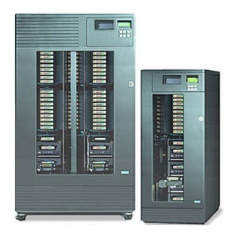
Page 32: Models
5433, 5466 58132, 58264 8111 8211, 8222 6430, 6460 68120, 68240 8433, 8466 88132, 88264 Figure 3-1 TLS-5000/6000/8000 Libraries TLS-5000 Feature/Model 5433 5466 58132 58264 Maximum number of tape drives Media capacity in cartridges (11 cartridges per magazine) Std. Std. -
Page 33: Model Identification
TLS-6000 Feature/Model 6110 6210 6220 6430 6460 68120 68240 Maximum number of tape drives Media capacity in cartridges (10 cartridges per magazine) Opt. Opt. Opt. Std. Std. Std. Std. Barcode Reader(s) I/O port for automated cartridge Opt. Opt. Std. Std. Std. -
Page 34: Major Assemblies
bay libraries because of their dual Drive Bays. All other models are single bay libraries. Differences among the models are noted where required. Depending upon the particular model, the TLS system devices may have the following features: • The wide LVD/SE SCSI interface is standard for the TLS and all available tape drives •... -
Page 35: Display
Display I/O Port Control Keys Key Lock Window Door Logo 6110/8111 62xx/82xx (54/64/84xx and 58/68/88xxx have the same external features) Figure 3-3 TLS Front View Product Description 501450 Rev. K... - Page 36 3.4.1.2 Rear Panel The AC power receptacle, line fuse, power switch and SCSI connectors are mounted on the TLS rear panel. TLS systems operate over a range of 100-120 VAC or 200-240 VAC, 50 Hz or 60 Hz. CAUTION When powering 58xxx, 68xxx and 88xxx libraries from 100-120 VAC, a 10-amp line fuse must be installed.
- Page 37 Top Cover Rear Panel Rear Service Panel Mounting Screws (6) Q-Link Rear Service Panel Ethernet Connector or Fibre Channel Option (Optional on some models) Interface Label SCSI Cable Access Power Switch Access Cover Quarter-turn Fasteners (4) (TLS-64/84xx models only) Nameplate FCC Label Access Cover Fuse Label...
- Page 38 SCSI Connectors Interface Label Thumbscrew Latch Drive Cooling Fan +12V LED +5V LED Figure 3-6 54xx, 64xx and 84xx Rear View with Access Cover Removed Product Description 501450 Rev. K...
- Page 39 Top Cover Q-Link Ethernet Connector (Optional on some models) Rear Panel Rear Service Panel or Fibre Channel Option (2) Rear Service Panel Mounting Screws (6) per Panel Interface Labels SCSI Cable Access Power Switch Nameplate Access Cover Quarter-turn Fasteners Air Filter (4) per Cover Cover (TLS-68/88xxx models only)
- Page 40 SCSI Connectors Drive Cooling Fan Thumbscrew Latch +12V LED +5V LED Figure 3-8 58xxx, 68xxx and 88xxx Rear View with Access Covers Removed (Also see Figure 3-7) 3-10 Product Description 501450 Rev. K...
-
Page 41: Tls Components
3.4.2 TLS Components This section defines some of the components, which make up the TLS. I/O Port Guide Shafts and Magazine Leadscrew Handler and Gripper Carriage Barcode Reader Private Slot (only in single bay models) Tape Drives Figure 3-9 TLS Major Internal Assemblies (Single Bay Library) Product Description 3-11 501450 Rev. - Page 42 3.4.2.1 Magazines TLS-6000 magazines hold up to ten tape cartridges while TLS-5000 and TLS-8000 magazines hold up to eleven tape cartridges. A magazine and its cartridges can be removed from the TLS and stored as a unit with a dust cover. Before storing a magazine, be sure to install its dust cover.
- Page 43 Magazine Dust Cover Magazine Rear Mounting Tabs (2) DLT Data Cartridge Magazine: Qualstar P/N 500953-01-3 LTO Data Cartridge Magazine: Qualstar P/N 501350-01-1 SAIT Data Cartridge Magazine: Qualstar P/N 501350-02-9 Figure 3-11 Magazine and Magazine Mount (DLT model shown) Product Description 3-13 501450 Rev.
- Page 44 3.4.2.2 Magazine Mounts The TLS contains one or more magazine mounts, (see Figure 3-11). Upgrade kits are available for the following models, which double the number of magazine mounts. From Model: To Model: 5433 5466 58132 58264 6210 6220 6430 6460 68120 68240...
-
Page 45: I/O Port
(10 for TLS-6000 libraries and 11 for TLS-5000 and TLS-8000 libraries). If the selected number of VIOP slots equals the number in a magazine, then the entire magazine may be removed as an I/O unit. -
Page 46: Carriage, Handler And Gripper
SCSI bus. This is a nature of the Tape Drives. NOTE DLT or SDLT tape drive assemblies cannot be installed in TLS-5000 or TLS-8000 libraries; LTO tape drive assemblies cannot be installed in TLS-5000 or TLS-6000 libraries and SAIT tape drive assemblies cannot be installed in TLS-6000 or TLS-8000 libraries. -
Page 47: Shuttle Mechanism
Pre-printed barcode labels, which are both human- and machine-readable, are available from a number of sources, including Qualstar. A barcode reader consists of a charge-coupled sensor (similar to that used in a video camera) and associated electronics. -
Page 48: Barcode Labels
Qualstar. Barcode labels must conform to ANSI/AIM BCI-1995, Uniform Symbology Specification Code 39. Please refer to PIN-040 at www.qualstar.com (click on Support tab) for more information. By default, the TLS expects a modulus 43 check character at the end of each label. -
Page 49: Location Designators
TLS Location Type SCSI Element Type Default Starting SCSI Address Magazine Storage Tape Drive Data Transfer 63000 I/O Port Import/Export 64000 Handler Medium Transport 65000 Table 3-5 Location Type to Element Type Mapping 3.5.3 Location Designators There are six types of Locations (physical cartridge locations) and they are referenced in the TLS menus by Location Designators. -
Page 50: Element Addresses
Shuttle For dual bay libraries the shuttle mechanism slot is designated by the letter . This location cannot be addressed by the Host. (Note: Mechanism appear as a unified Medium-Transport element to a SCSI host.) Drives Tape drive locations, assigned from top to bottom, are designated through for Single Bay libraries. -
Page 51: Inventory Database
If the validity data is true, then its associated data is correct. If the validity data is false, then its associated data may not be correct, but usually contains the last-known data. Additional definitions for the database are included in the TLS-5000/6000/8000 SCSI-2 Interface Manual (Qualstar document number 501205). Product Description 3-21 501450 Rev. -
Page 52: Inventory Validation
3.5.7 Inventory Validation When the inventory database is invalidated, the changer scans all locations before it does anything else, and stores the cartridge location information in its internal inventory database. If a barcode reader is installed (optional on some models), and barcode labels are affixed to the cartridges, barcode information is also stored as part of the inventory information. -
Page 53: Random And Multi-Sequential (Multiple Stacker) Operation
• Configure the TLS including Drives, SCSI and Logical Libraries • Dump diagnostic logs • Upload new TLS firmware • Upload new Q-Link firmware • Move inventory • Clean or unload tape drives Additionally, Q-Link can be configured to e-mail event or fault messages to a list of support staff when a name server and SMTP server are available. -
Page 54: Logical Libraries
3.8 Logical Libraries When shipped from the factory, all TLS-5000, TLS-6000 and TLS-8000 libraries look like a single library with all of its tape drives and storage slots dedicated to the random operation of Library-“a”. -
Page 55: Cartridge Location Designator Diagrams
3.10 Cartridge Location Designator Diagrams 6210 I/O Port Slot 6110 Magazine Slots Magazine Slots Private Slot Handler Handler Drive Drive Figure 3-13 6110 and 6210 Cartridge Location Designators 6220 I/O Port Slot 1A10 2A10 1A09 2A09 1A08 2A08 1A07 2A07 1A06 2A06 Magazine Slots... - Page 56 6430 I/O Port Slot 1A10 3A10 5A10 1A09 3A09 5A09 1A08 3A08 5A08 1A07 3A07 5A07 1A06 3A06 5A06 Magazine Slots 1A05 3A05 5A05 1A04 3A04 5A04 1A03 3A03 5A03 1A02 3A02 5A02 1A01 3A01 5A01 Face Private Slot Handler Drives Figure 3-15 6430 Cartridge Location Designators 3-26...
- Page 57 6460 I/O Port Slot 1A10 2A10 3A10 4A10 5A10 6A10 1A09 2A09 3A09 4A09 5A09 6A09 1A08 2A08 3A08 4A08 5A08 6A08 1A07 2A07 3A07 4A07 5A07 6A07 1A06 2A06 3A06 4A06 5A06 6A06 Magazine Slots 1A05 2A05 3A05 4A05 5A05 6A05 1A04...
- Page 58 68120 I/O Port Slot . . I . . L1B10 L3B10 L5B10 R1B10 R3B10 R5B10 L1B09 L3B09 L5B09 R1B09 R3B09 R5B09 L1B08 L3B08 L5B08 R1B08 R3B08 R5B08 L1B07 L3B07 L5B07 R1B07 R3B07 R5B07 Magazine Slots Magazine Slots L1B06 L3B06 L5B06 R1B06 R3B06 R5B06...
- Page 59 68240 I/O Port Slot I . . L1B10 L2B10 L3B10 L4B10 L5B10 L6B10 R1B10 R2B10 R3B10 R4B10 R5B10 R6B10 L1B09 L2B09 L3B09 L4B09 L5B09 L6B09 R1B09 R2B09 R3B09 R4B09 R5B09 R6B09 L1B08 L2B08 L3B08 L4B08 L5B08 L6B08 R1B08 R2B08 R3B08 R4B08 R5B08 R6B08...
- Page 60 8222 I/O Port Slot 1A11 2A11 1A10 2A10 1A09 2A09 1A08 2A08 1A07 2A07 Magazine Slots 1A06 2A06 1A05 2A05 1A04 2A04 1A03 2A03 1A02 2A02 1A01 2A01 Face Private Slot Handler Drives Figure 3-20 8222 Cartridge Location Designators 5433 & 8433 I/O Port Slot 1A11 3A11...
- Page 61 5466 & 8466 I/O Port Slot 1A11 2A11 3A11 4A11 5A11 6A11 1A10 2A10 3A10 4A10 5A10 6A10 1A09 2A09 3A09 4A09 5A09 6A09 1A08 2A08 3A08 4A08 5A08 6A08 1A07 2A07 3A07 4A07 5A07 6A07 Magazine Slots 1A06 2A06 3A06 4A06 5A06...
- Page 62 58264 & 88264 I/O Port Slot . . I . . L1B11 L2B11 L3B11 L4B11 L5B11 L6B11 R1B11 R2B11 R3B11 R4B11 R5B11 R6B11 L1B10 L2B10 L3B10 L4B10 L5B10 L6B10 R1B10 R2B10 R3B10 R4B10 R5B10 R6B10 L1B09 L2B09 L3B09 L4B09 L5B09 L6B09 R1B09 R2B09...
-
Page 63: Control Panel
Control Panel 4.1 Introduction The control panel (Figure 4-1) is composed of a Display, six Control Keys and an I/O port. The control panel is used to configure and control the library system and to add or remove cartridges from the library. An audible alarm is provided behind the control panel for alerting the user to several different types of events, like a door open condition, or a tape cartridge inventory violation. -
Page 64: Control Keys
4.3 Control Keys Five of the six control keys below the display are used to access the menu system. The sixth control key, the (Daisy) key, is used to manually operate the I/O port, or park the changer’s carriage at the top or bottom of its range of motion. The control key functions are explained in detail in Chapter 6. - Page 65 DLT Tape Cartridge Write Enable/Protect Tab Window IBM LTO Tape Cartridge Write Enable/Protect Tab Window (shown unlocked) HP LTO Tape Cartridge SAIT Tape Cartridge Figure 4-3 Inserting a Tape Cartridge into the I/O Port NOTE DLT tape cartridges are write-protected when the Enable/Protect tab is moved to the left, showing an orange stripe through the tab's window.
- Page 66 This page left blank intentionally. Control Panel 501450 Rev. K...
-
Page 67: Installation
Installation 5.1 Installation Considerations When selecting a location for the TLS, be sure to consider the unit weight and provide a stable operating location. These tape libraries are not intended for use in mobile applications. They were designed for use in an office environment. Also remember to provide sufficient free space around the unit to allow for loading/unloading media/drives, establishing cable connections, and airflow considerations. -
Page 68: Power Source Disturbances
5.1.3 Power Source Disturbances The TLS will continue to operate uninterrupted and without damage over a one-cycle line dropout, however, longer power disturbances can occur. Qualstar recommends the use of an Uninterruptible Power Supply (UPS) to minimize the potential for data loss in case of an unexpected power interruption. -
Page 69: Ventilation
There are multiple universal input, line-switching power supplies in each model. The supplies feature a soft-start circuit to eliminate current surges on the AC mains when power is applied. They also feature an over-voltage protection circuit, that protects the robotics electronics and the tape drives in the event of a power supply failure. 5.1.4 Ventilation When selecting a location for the TLS, be sure to allow about four inches of clearance around the TLS, to be sure that nothing will block the air intake and exhaust ports. - Page 70 1.00 2.75 Stabilizer Feet (2) Typical EMPTY SHIPPING MODEL HEIGHT WIDTH DEPTH WEIGHT WEIGHT (in/cm) (in/cm) (in/cm) (lb/kg) (lb/kg) 6110, 8111 22.9 / 58.2 13.1 / 33.3 24.9 / 63.2 58 / 26.3 90 / 40.8 6210, 6220 34.7 / 88.1 13.1 / 33.3 24.9 / 63.2 89 / 40.3...
- Page 71 Dimensions shown in inches 37.25 30.5 1.12 61.9 EMPTY SHIPPING MODEL HEIGHT WIDTH DEPTH WEIGHT WEIGHT (in/cm) (in/cm) (in/cm) (lb/kg) (lb/kg) 58132, 58264 61.9 / 157.3 37.25 / 94.62 30.5 / 77.5 359 / 163 602 / 273 68120, 68240 88132, 88264 Shipping weights include the TLS, empty magazines and accessories.
-
Page 72: Stabilizer Feet Installation
Other Weights Weight (lb/kg) Tape Drive/Carrier Assembly 8.0 / 3.6 Magazine 2.0 / 0.9 Data Cartridge 0.5 / 0.23 SCSI Bridge (Jumper) Cable 0.3 / 0.13 Table 5-2 Other Weights 5.2 Stabilizer Feet Installation Each 54xx, 62xx, 64xx, 82xx and 84xx series library must have stabilizer feet installed on the sides of the cabinet to meet safety requirements. - Page 73 Reinstall two of the screws removed in step 2 to secure the Stabilizer Foot. Lower the cabinet back down. Repeat steps 3 through 5 to install a Stabilizer Foot for the left side of the cabinet. Stabilizer Feet Stabilizer Foot Bottom/Front of Unit Top/Front of Unit Figure 5-4 Stabilizer Foot Installation...
-
Page 74: Locking Casters On Dual Bay Models
5.3 Locking Casters on Dual Bay Models After a 58xxx, 68xxx or 88xxx series library has been moved into its desired position, the casters on the bottom of the TLS must be locked. NOTE Any repair or replacement of the casters on the bottom of the TLS should only be preformed by qualified service personnel. -
Page 75: Supported Tape Drives
Turn off the AC power switch and remove the power cord. 5.5 Supported Tape Drives All tapes drives used in TLS-5000, TLS-6000 and TLS-8000 libraries are made by their manufacturer expressly for use in Qualstar tape libraries and must be supplied by Qualstar or its authorized representatives. -
Page 76: Dlt Tape Cartridge Inspection
• Never apply adhesive labels to the tape cartridge anywhere except in the recess provided on the front side (same side as the write-enable/protect switch). Labels applied elsewhere could cause the cartridge to become jammed inside a tape drive or magazine. •... - Page 77 reel lock which can break if the cartridge is dropped. This may cause any rattling sound when the tape cartridge is gently shaken. If this reel lock tab is not visible do not use the cartridge. Also located on the bottom of the tape cartridge is the spring-loaded hub.
- Page 78 Leader Loop Leader Loop Figure 5-8 Open Door on Tape Cartridge Showing Tape Leader in Correct Position Examples of three different tape cartridge loop problems are shown in Figure 5-9. No tape cartridge that exhibits the problems shown should be used in a tape drive.
-
Page 79: Installing A Tape Drive Assembly
5.7 Installing a Tape Drive Assembly CAUTION This installation procedure should only be performed by qualified service personnel. Be sure to turn the TLS’ power off before installing or removing tape drive assemblies. Model 54xx, 58xxx, 6110, 64xx, 68xxx, 8111, 84xx and 88xxx libraries are shipped with the tape drive assemblies that were ordered with the TLS already installed. - Page 80 IMPORTANT: A filler plate must be installed over every unused Tape Drive Assembly opening or else the positive-pressure cooling system will not function properly. Drive Filler Plate is Qualstar Part Number 501128-01-1 and the 6-32 screws are Part Number 706-0005-1.
-
Page 81: Installation
When installing Quantum DLT 4000, 7000 and 8000 drives check the left and right sides of the Tape Drive Assembly to determine if the cover plates are closed (Figure 5-12). Both plates must be closed before installing a Tape Drive Assembly in a TLS. - Page 82 Drive Cooling Fan SCSI Connectors Carrier Handle Carrier Handle + 12V LED Nameplate + 5V LED Thumbscrew Latch Fibre Channel Connector Fibre Channel Connector Link LED Activity LED LTO Direct Fibre Attach SAIT Direct Fibre Attach Tape Drive Tape Drive The Direct Fibre Attach Tape Drives require commonly available LC Duplex Multimode fibre channel cables.
-
Page 83: Access Cover Replacement
Mounting Rails Mating Connector Guide Pins Figure 5-14 Model 6220 - Rear View Turn the Thumbscrew Latch on the Tape Drive Assembly all the way clockwise by hand, until it is finger-tight (Figure 5-13). CAUTION Do not use pliers or any other tool to tighten the Thumbscrew Latch. Using a tool to tighten the Thumbscrew Latch might permanently damage the latch. - Page 84 SCSI bus. Therefore, wait until the changer becomes ready, before turning on the power to the host system, otherwise the host may not be able to see the drives. When the changer is ready, display Line 1 indicates and the TLS' model number, while the rest of the display is Qualstar blank. 5.7.4.2 Custom Configuration If desired, follow the steps below to change a drive's configuration information.
- Page 85 Press the (DOWN) key (if necessary) to select a drive number (Td), then press the ENTER key to view the menu below. (The figure below shows the default menu for an installed DLT 8000 drive.) C•Drive•••••••••••T1 Mdl: DLT8000 SN:??????????????? Enabled: Revision: xxxx SCSI Bus:...
-
Page 86: Tape Drive Assembly Removal
After completing all of the desired configuration changes, press the MENU key, then press the EXIT key, to exit the menu system. Drive Position SCSI Id Number Table 5-3 Default Tape Drive SCSI Id Numbers NOTE The remaining values in this menu (except for the ) relate to sequential operation. -
Page 87: Installing Media
5.9 Installing Media 5.9.1 Static Precautions Before handling data cartridges, it is a good idea to eliminate any static charge that may exist. To protect the data stored on the tape cartridges, just follow the simple procedure below before loading, moving, or removing any data cartridges. Open the TLS' door and locate the grounding strap connected between the door and the lower-left corner of the TLS (Figure 5-15). -
Page 88: Loading A Magazine
5.9.2 Loading a Magazine CAUTION Do not drop tape cartridges. If a cartridge is dropped, the tape may be damaged without any visible signs. Using a damaged cartridge can seriously damage a tape drive. Magazines may be loaded before or after being installed in the TLS. DLT cartridges are write protected when the Enable/Protect tab is moved to the left, with the orange strip showing through the tab’s window. -
Page 89: Installing And Removing Magazines
CAUTION Tape cartridges can be damaged by tilting a magazine opening downwards (the tapes might fall out). NEVER TILT A LOADED MAGAZINE DOWNWARDS! Always keep loaded magazines upright or on its back. 5.10 Installing and Removing Magazines Refer to Figure 5-17 for this procedure. The magazines are designed for easy installation and replacement without tools. - Page 90 Magazine Dust Cover Magazine Rear Mounting Tabs (2) DLT Data Cartridge Magazine: Qualstar P/N 500953-01-3 LTO Data Cartridge Magazine: Qualstar P/N 501350-01-1 SAIT Data Cartridge Magazine: Qualstar P/N 501350-02-9 Figure 5-17 Magazine and Magazine Mount (DLT model shown) 5-24 Installation...
-
Page 91: Scsi Interface
5.11 SCSI Interface The standard SCSI control-interface to the Medium-changer (MC) is both Low Voltage Differential (LVD) and Single-Ended (SE) capable. This is defined by ANSI as Multimode Low Voltage Differential or MLVD and is also called LVD/SE. The interface can operate in the narrow or wide modes. All available tape drives support wide LVD/SE operation. -
Page 92: Connecting The Scsi Data Cable(S)
Bridge Cable Connectors in order, top to bottom. (see 4 and 5 for example). Connect the bottom tape drive Cable Connector to the SCSI host computer. NOTE For Qualstar Part Numbers of terminators see Table 5-5. The Qualstar Part Number for a Bridge Connector Cable is 501087-01-9. 5-26 Installation 501450 Rev. -
Page 93: Scsi Bus Termination
* Assuming that the Medium Changer is connected to the host via SCSI. See the Fibre Channel Option Installation and Operation Manual (Qualstar P/N 501440) if the Medium Changer is connected with the Fibre Channel Option. Figure 5-19 SCSI and DFA Connection Examples 5.11.4 SCSI Bus Termination... -
Page 94: Scsi Termination Power
SCSI Bus Type QUALSTAR P/N Low Voltage Differential or 117-0011-9 Single-Ended – LVD/SE Table 5-5 68 Pin SPI-2 Terminators 5.11.5 SCSI Termination Power The TLS can supply up to 2 amps of termination power to the SCSI bus connected to the MC. -
Page 95: Access Cover
(TPWR) disconnects the termination power (TERMPWR) on the SCSI bus. The TLS is shipped with the jumper installed and Qualstar recommends that it be installed if the changer is at the end of the SCSI bus. If the jumper is removed, TERMPWR must be available from another device on the SCSI bus. -
Page 96: Testing Basic Scsi Operation
5.11.8 Testing Basic SCSI Operation The MC, can now be tested to verify that it responds correctly to commands from the host. The simplest way of doing this is to issue a Test Unit Ready command to the MC. If the MC returns a GOOD status, then it is certain that the SCSI communications protocol and SCSI cable (and associated line drivers and receivers) are operational. -
Page 97: The Menu System
The Menu System The menu system allows the user to perform manual operations. It also allows a qualified individual to make configuration changes to the changer and monitor maintenance and operation. This chapter explains the menu system, the types of information it presents, and how to use it. -
Page 98: The Enter Control Key
If a multiple-choice value is highlighted, the (UP) and (DOWN) keys cycle through the available choices. If the (UP) or (DOWN) key is pressed and held down, the control key's action repeats at a rapid rate. 6.1.3 The ENTER Control Key The ENTER key behaves as follows: •... -
Page 99: The Exit Control Key
6.1.4 The EXIT Control Key The EXIT key behaves as follows: While editing a menu item’s value, pressing the EXIT key exits the editor and restores the pointer to the menu item. Note that all values changed during editing are actually changed, exiting does not undo those changes. - Page 100 • If no tape is inserted, the I/O port slot retracts one or two minutes after the I/O port is summoned. Use the Configuration\Advanced\Changer\I/O menu item to select either the one or two minute delay time. Port CALL Key The host software then determines where the tape cartridge should be stored. The storage location can also be manually determined using the menu system provided the menu system has not been locked by the system administrator.
-
Page 101: The Top Menu
6.1.5.2 Parking the Handler While the operating display is visible, press and hold down the (Daisy) key to view (Daisy) key menu (Figure 6-2), press the (UP) or (DOWN) key to execute command, then release both keys. PARK HIGH PARK LOW 6.2 The Top Menu To see the Top Menu, turn on the TLS, wait until the display shows model number, then press the MENU key. -
Page 102: Menu Elements
6.3 Menu Elements 6.3.1 Menu Items Line 1 of any menu display always indicates the name of the menu right justified, with the exception of the Top Menu, where menu names are left justified. The name of, or an acronym for, the parent menu will precede the menu name and will be left justified. -
Page 103: Values
These values can contain up to 96 different characters (see Section 6.3.4.4), including ten numerals (0-9), upper and lower case letters and special characters, like spaces, dashes, etc. There is no roll-over between digits. Example: Qualstar TLS-8211 6.3.2.3 Multiple-Choice Values Each multiple-choice value has its own list of valid choices. -
Page 104: Location Designators
6.3.3 Location Designators Refer to Section 3.5 for definitions of locations and SCSI elements. A Location Designator contains six characters used to describe any physical location. A “p” in the first character signifies a physical location and then the five remaining characters are defined below. -
Page 105: Editing Values
The last storage location in the first magazine: Face 1, Story A, Slot 11 (single bay models) p.1A11 Note that TLS-6000 models have 10 slots and TLS-5000 and TLS-8000 models have 11. The first magazine storage location: Left Carousel, Face 1, Story A, Slot 1... - Page 106 6.3.4.2 Editing non-Multiple-Choice Values If only the first character of the value is highlighted with a flashing block cursor after pressing the ENTER key, the value is either numerical, alphanumerical, or a cartridge location. These values may be edited one character at a time using the ENTER key to select the character to be edited and then using the (UP) or (DOWN) key to change the character's value.
- Page 107 (space) ¥ “ → & < ← ‘ > Table 6-5 Alphanumeric Characters and their “ACSII” Hexadecimal Equivalents. 6.3.4.5 Editing Cartridge Location Values (Designators) There are two ways to edit cartridge location designators with either the (UP) or (DOWN) key. First, like an alphanumeric value, a cartridge location designator can be edited one character at a time.
-
Page 108: The Menu Hierarchy
The Maintenance menu is designed to help a qualified repair technician diagnose and repair the TLS. Its functions are outside the scope of this manual and are fully explained in the TLS-5000/6000/8000 Technical Service Manual (Qualstar document number 501090). The Operation menu is designed for the user. It allows an operator to perform tasks associated with the operation of the TLS. -
Page 109: Alerts
6.6 Alerts Alerts are important messages, which take over the entire display and remain visible until dismissed by the operator. If the alert message is longer than four lines, a down arrow in the lower right corner indicates more text is visible by scrolling the display with the (DOWN) key. - Page 110 This page left blank intentionally. 6-14 The Menu System 501450 Rev. K...
-
Page 111: Resource Management
Resource Management 7.1 Introduction The physical resources of a TLS-5000, 6000 or 8000 tape library may be sub-divided for multiple purposes by allocating tape drives and storage locations (Magazine slots) to specific partitions. The Handler is a shared resource which cannot be dedicated to any single task. -
Page 112: Sequential Operations
Medium-changer knows the SCSI ID of the host computer that is talking to it and can therefore indicate to that host that only a pre-determined (pre-configured) list of physical resources are available to it. This masquerade can be done for a total of four libraries –... -
Page 113: Resource Inventory
TLS-88264 There are 10 slots per magazine in TLS-6000 models and 11 slots per magazine in TLS-5000 and 8000 models. Not all mounts may have magazines installed. Table 7-1 Available TLS Resources by Model Fill out the TLS-Model line and the Tape Drive Allocation Table below to indicate which resources are installed in your TLS as well as some of their facts (why not use a pencil or first make a copy of this page). -
Page 114: Resource Allocation Worksheet
7.5 Resource Allocation Worksheet TLS-Model: TLS-_____________ Device Make Model SCSI Bus SCSI ID Allocated to:* Qualstar TLS-54xx or TLS-6000 or TLS-8000 L-MC Qualstar TLS-58xxx or TLS-68xxx or TLS-88xxx R-MC Qualstar TLS-58xxx or TLS-68xxx or TLS-88xxx Factory Default Values are shown in brackets [default value] * Allocated to: [Library-a], Library-b, Library-c, Library-d, or Sequential # (where # is the Drive number). - Page 115 Partition Sequential Input Mag. Slots Output Mag. Slots* (drive specific) Mode First Last First Last Sequential-T1 Sequential-T2 Sequential-T3 Sequential-T4 Sequential-LT1 Sequential-LT2 Sequential-LT3 Sequential-LT4 Sequential-RT1 Sequential-RT2 Sequential-RT3 Sequential-RT4 Sequential Modes: Sequential, Recycle and Dual-Bin (see Chapter 10) * Output Magazine Slots used for Dual-Bin mode only. Must be same or greater number of slots than the Input magazine slots.
-
Page 116: Resource Allocation Examples
Sequential drives running in the Dual-bin mode require two identical slot allocations because of their separate input- and output-bins. The input and output bins need not be adjacent, although that is a good practice. Verify that only existing resources have been allocated and that there are no resources allocated to more than one partition. -
Page 117: Configuring The Tls For The Desired Allocations
Partition Sequential Input Mag. Slots Output Mag. Slots* (drive specific) Mode First Last First Last Sequential-LT1 Sequential-LT2 Sequential-LT3 Sequential-LT4 Sequential-RT1 Sequential-RT2 Sequential R4B01 R4B10 Sequential-RT3 Dual-Bin R5B01 R5B10 R6B01 R6B10 Sequential-RT4 * Presently, the I/O port can be assigned to only one logical library however a VIOP may be assigned to any logical library. - Page 118 menu Configuration\Advanced\Library ? Variable Value From Column # of Table 7-3 Enable: Drive First: Drive Last: Fixed First: Fixed Last: Slot First: Slot Last: VIOP First: VIOP Last: I/O Port: “?” represents the partition being configured (a, b, c, or d). If an I/O port is installed, then it may be allocated to only one partition however a VIOP may be assigned to any logical library.
- Page 119 Configure each library and drive according to all of the parameters of Sections 8.13 and 8.20. Now enable the active Logical Libraries by changing their values to . If the Configuration\Advanced\Library ?\Enable: value cannot be set to ON, the problem may be that a resource has been allocated to more than one library or sequential drive.
- Page 120 This page left blank intentionally. 7-10 Resource Management 501450 Rev. K...
-
Page 121: The Configuration Menu
Configuration: OFF Inventory: Master: Figure 8-1 The Configuration Menu (Part 1) menu is used to customize the operation of the TLS-5000, Configuration TLS-6000 and TLS-8000 to meet the system requirements. The Configuration menu consists of several sub-menus, some affecting the unit's interaction with the SCSI system, and others affecting the unit's interaction with the user. - Page 122 The following sections explain each menu in detail. An explanation of the display and detailed instructions on navigating the menu system are contained in Chapter 6. Not all values or menu items appear at all times; some depend upon the model of library in use, other configuration parameters and incomplete prerequisite conditions.
-
Page 123: Configuration/Security Menu
The Legends in Figure 8-1 and Figure 8-2 indicate the types of digits found in the value items of the menu's sub-menus. An explanation of each type Configuration is given below. Legend Explanation Decimal digit (0-9): A Decimal value contains one or more decimal digits, indicating the present value of the item. -
Page 124: Door Lock
Setting any or all of the security locks to does not disable navigation through the menu structure, rather it simply prevents certain values from being changed, or the execution of certain commands. When an item is secured by more than one lock, all of the locks used to secure the item must be set to , before the locked item can be changed or executed. - Page 125 Door Configuration Inventory Master Lock Lock Lock Lock Menu Item \Configuration SCSI ID:, SCSI ID Left:, SCSI ID Right: SET TO DEFAULTS \Configuration\Advanced\ all items Control Panel\Alarm \Configuration\Advanced\ all items Control Panel\Display \Configuration\Advanced\Changer Busy:, Door Open:, Filter Days:, LabelCheckChar:, Power On Clear:, Use Private Slot: \Configuration\Advanced\Changer\ Motion:, Prevent:...
-
Page 126: Configuration Menu
8.2 Configuration Menu •••••••Configuration •Advanced •Drive •Q-Link SCSI ID: SCSI ID Left SCSI ID Right: •Security SET TO DEFAULTS This menu is the root configuration menu. It contains sub-menus and commands. NOTE Note that the bold menu items are model dependent. Libraries with single bays have a single sub-menu while libraries with dual bays (58xxx/68xxx/88xxx models), instead have SCSI ID sub-menus. -
Page 127: Configuration\Advanced Menu
The changer returns a CHECK CONDITION status with a Sense Key value of NOT READY, plus the appropriate information in the ASC and ASCQ data. Refer to the TLS - 5000/6000/8000 SCSI-2 Interface Manual (Qualstar document number 501205). The Configuration Menu... -
Page 128: Door Open
8.4.2 Door Open This value determines the action the carriage/handler takes when the door is opened while the carriage/handler is moving. ABORT The carriage/handler stops and does not resume operation when the door is closed (default value). HOLD The carriage/handler stops, and then resumes operation when the door is closed. -
Page 129: Power On Clear
6110 magazine slots or the I/O port in any model. 8.5 Configuration\Advanced\Changer\Door Lock Menu CA•Changer•Door Lock Motion: Prevent: This feature is currently not available on TLS-5000, TLS-6000 and TLS-8000 libraries. The Configuration Menu 501450 Rev. K... -
Page 130: Configuration\Advanced\Changer\Inventory Menu
8.6 Configuration\Advanced\Changer\Inventory Menu CA•Changer•Inventory Invalidate: SENTRY Label Scan: ALWAYS Mag. Labels: SOME PowerOn:INVALIDATE Seq. Labels: SOME Source Drive: SourceI/O Port: NO NOTE All items in this menu are locked by the Configuration Lock and the Master Lock. See Section 8.1. This menu defines the conditions under which the inventory will be rescanned, and which items will be rescanned. -
Page 131: Invalidate
8.6.1 Invalidate This value indicates the condition that invalidates the inventory. is a multiple-choice value with the options listed below: Invalidate SENTRY The inventory is invalidated whenever the Inventory Sentry Beam is disturbed (default value). DOOR The inventory is invalidated whenever the door is opened. NEVER The changer never invalidates the inventory. -
Page 132: Poweron
8.6.4 PowerOn This value determines whether or not the inventory database is invalidated when TLS power is removed or lost. is a multiple-choice value with the following options: PowerOn INVALIDATE The inventory database is invalidated whenever TLS power is applied. This might be the preferred setting if the door is left unlocked (default value). -
Page 133: Source I/O Port
Next, the cartridge is moved from the tape drive, to any slot. The tape drive’s element address is not included in the determination, so the cartridge's source address is 8, its more recent element address. Example 2: The value is set to Source Drive First, a cartridge is moved from a magazine slot whose element address is 8, to a tape drive whose element address is 15. -
Page 134: Configuration\Advanced\Changer\I/O Port Menu
8.7 Configuration\Advanced\Changer\I/O Port Menu CA•Changer••I/O Port CALL Key: 1 MIN Export: Extended:NOT READY Import: Import Scan: Slot Access: BOTH NOTE All items in this menu are locked by the Configuration Lock and the Master Lock. See Section 8.1. menu facilitates control Configuration\Advanced\Changer\I/O Port of certain aspects of the I/O port operation. -
Page 135: Export
8.7.2 Export This value controls the changer’s access to the I/O port slot. It also sets the value of the Export Enable bit in the SCSI Read Element Status and Read Volume Element Address commands. is a multiple-choice value with the options listed below. Export The changer is allowed to place cartridges into the I/O port slot, and the value of the Export Enable bit is set to one (default value). -
Page 136: Import Scan
(58xxx/68xxx/88xxx models), Fibre Channel instead have sub-menus. FC LEFT FC RIGHT All other Fibre Channel related menu items are discussed in the Fibre Channel Option Installation and Operation Manual (Qualstar document number 501440). 8-16 The Configuration Menu 501450 Rev. K... -
Page 137: Model
menu describes the Configuration\Advanced\Changer\Mechanics hardware configuration of the TLS. The values in this menu are factory-set to reflect the unit's configuration at the time of shipping and are not changeable. In the following paragraphs, no default values are given, as they vary from unit to unit. -
Page 138: Configuration\Advanced\Control Panel Menu
8.9 Configuration\Advanced\Control Panel Menu CA•••••Control Panel •Alarm Backlight: Contrast: •Display menu allows customizing the Configuration\Advanced\Control Panel control panel to suit the environment. The Control Panel Display and contrast can be changed with this menu. 8.9.1 Backlight This value controls the backlighting of the Control Panel Display. The backlight is always on. -
Page 139: Handler Error
8.10.2 Handler Error This alarm sounds whenever the handler has a problem, which requires manual intervention (e.g. a stuck cartridge). The default value is 3700 8.10.3 Inventory Violation A condition has occurred, such as breaking the Inventory Sentry beam, which may have compromised the integrity of the inventory. -
Page 140: Configuration\Advanced\Library Menu
Display Files There are three sets of display data: , and . The host can CURRENT SAVED DEFAULT read all three sets of display data, and can change the set or the set. CURRENT SAVED In addition, the menu can be used to manually edit the CACP Display CURRENT files. -
Page 141: Configuration\Advanced\Library\? Menu
8.13 Configuration\Advanced\Library\? Menu C•Advanced•Library•? Enable: Drive First:llllll Drive Last: llllll Drives: Slot First: llllll Slot Last: llllll Slots: VIOP First: llllll VIOP Last: llllll VIOPs: DT Access: ??????? DT Serial: •ElementAddress Inq: NATIVE Volume Tag Pad:SPC This menu is used to enable a given logical partition (logical library) and to allocate resources to the enabled partitions within the TLS. -
Page 142: Drive Last
8.13.3 Drive Last This value defines the last tape drive assigned to this partition. The drives are numbered from T1 to T4 in single bay libraries. Drives in dual bay libraries are numbered LT1 to LT4 and RT1 to RT4 for the respective sides of the library. All tape drives from Drive First: to Drive Last: (inclusive) will be allocated to the selected partition. -
Page 143: Viop Last
8.13.12 DT Serial This value determines if the tape drive serial numbers are reported to the SCSI host as part of the Data Transfer Element Descriptor. Refer to the TLS-5000/6000/8000 SCSI Interface Manual (Qualstar document number 501205) for details. The Configuration Menu 8-23 501450 Rev. -
Page 144: Inq
The default value, causes the tape drive serial numbers to be padded with 00-FILL the NUL character (hex 00). Some software and equipment manufacturers do not adhere to this standard and pad the field with spaces. In order to provide emulation capabilities for these units, the value allows selecting from the DT Serial... -
Page 145: Configuration\Advanced\Library\Elements Address Menu
The number of each element type varies with the logical library configuration. The element address values are decimal, with a range of from zero to 65,535, and leading zeroes are suppressed in the display. See the TLS-5000/6000/8000 SCSI-2 Interface Manual for additional information on element addresses. -
Page 146: Configuration\Advanced\Library\Elementaddress\Display
8.14.1 Configuration\Advanced\Library\ElementAddress\Display There are two sets of element addresses. They are selectable in the menu and function as follows: SAVED This set of element addresses stored in non-volatile memory. set is the set that will be in use following a Reset SAVED event. -
Page 147: Configuration\Advanced\Log Menu
The changer maintains a log that consists of a list of internal events. This menu determines which events are logged. The purpose of the log is to assist in testing and isolating problems with the assistance of Qualstar support personnel. Each item in the... -
Page 148: Configuration\Advanced\Scsi Menu
8.16 Configuration\Advanced\SCSI Menu C•Advanced••••••SCSI C•Advanced SCSI•Left CA••••••••SCSI•Right •Library Disconnect: Enable: Interface: LVD/SE LUN: Parity: ABORT Synchronous: NOTE Many of the items in this menu are locked by one or more of the security locks. See 8.1 for details. This menu allows configuring the Medium-changer to match the system’s SCSI requirements. -
Page 149: Interface
is a multiple-choice value with the options listed below: Enable BUSY The Medium-changer responds to any SCSI command with a status of BUSY and the command is not executed. INFO The Medium-changer responds to all SCSI commands, except ONLY INQUIRY and REQUEST SENSE, with a status of BUSY (see BUSY above). -
Page 150: Parity
8.16.5 Parity This value determines what action the Medium-changer will take when it detects a parity error on the SCSI bus during a Command Out, Data Out, Status Out, or Message Out phase. is a multiple-choice value with the options listed below: Parity MESSAGE Use this option if the host adapter supports messages... -
Page 151: Configuration\Advanced\Scsi Inquiry Menu
8.17 Configuration\Advanced\SCSI Inquiry Menu CA•SCSI••••••Inquiry CA•SCSI••••••Inquiry Set: NATIVE Set: EXABYTE 10e Device-Specific (8 bytes) 0880020233000010 0880020233000010 QUALSTAR EXABYTE Vendor ID (8 bytes) TLS-???? EXB-10e Product ID (16 bytes) ?.?? ?.?? Product Revision (4 bytes) 0000000000000000 0000000000000000 Vendor-Specific (8 bytes) 0000000000000000... - Page 152 Selecting an Inquiry String Use the control keys as follows to copy the desired Inquiry string into the display. See Figure 8-4 for a list of available Inquiry data files. With the pointer at , press the ENTER key. The name of a data file is Set: highlighted.
- Page 153 Press ENTER and edit the line as previously described. When all the lines are satisfactory, press EXIT. NOTE If Custom string was created and then a predefined string is later chosen to be edited, the Custom string is deleted from the menu. Follow these steps to change to a different Inquiry string: Press the MENU key once to display the Top Menu...
-
Page 154: Configuration\Advanced\Scsi\Library Menu
8.18 Configuration\Advanced\SCSI\Library Menu CA•SCSI••••••Library CAS•Left•••••Library CAS•Right••••Library Initiator 0: Initiator 1: Initiator 2: Initiator 3: Initiator 4: Initiator 5: Initiator 6: Initiator 7: Initiator 8: Initiator 9: Initiator 10: Initiator 11: Initiator 12: Initiator 13: Initiator 14: Initiator 15: NOTE All items in this menu except Display are locked by the Configuration Lock and the Master Lock. See Section 8.1. -
Page 155: Configuration\Drive Menu
8.19 Configuration\Drive Menu Configuration••Drive •T1:DISABLED •T2:RANDOM •T3:1A01 •T4: NONE •LT1: NONE •LT2: NONE •LT3: NONE •LT4: NONE •RT1: NONE •RT2: NONE •RT3: NONE •RT4: NONE menu has up to eight sub-menus – one for each tape Configuration\Drive drive position. For single bay libraries the sub-menus are T1-T4. For dual bay libraries LT1 thru RT4 replace T1-T4 and represent the drives in both the left and right drive bays. -
Page 156: Configuration\Drive\?T? Menu
The selectable values in this menu are TLS model and option dependent. Refer to Qualstar Product Information Note 014 for an up-to-date list of supported DLT, LTO and SAIT tape drives. Whenever adding or removing tape drives from the system, this menu item must be used to reflect the change. -
Page 157: Enabled
model value is set to . The selection in this item is not affected by the NONE SET TO command. DEFAULTS 8.20.2 SN This value indicates the serial number of the tape drive. The value has no effect on the operation of the library and it is not changeable. 8.20.3 Enabled The drive is considered ready to be loaded. - Page 158 The default tape drive SCSI ID values are 1 through 4, for tape drives through respectively in single bay libraries. For dual bay libraries the SCSI ID values are 1 through 4 for tape drives LT1 through LT4 and for tape drives RT1 through RT4 the SCSI ID values are 5, 6, 8 and 9, respectively.
-
Page 159: Wwn
NOTE All drives may be operated from a narrow initiator, but the effective termination must be wide termination. NOTICE Changing the SCSI ID of a tape drive via the menu system causes the TLS to change the state of signals connected to the tape drive. However, the tape drive only checks these signals when power is applied or following a SCSI bus reset. -
Page 160: Mode
(five periods). To set the value to “..”, move the cursor to the third column and then use the Up arrow key until “..” is displayed. When this tape drive (upper right corner of this menu) is selected from the menu, the changer will go to this location to fetch the Operations\Clean Drive cleaning cartridge. -
Page 161: Input First
the library when set for . Any tape drives configured for INVENTORY POWER-ON the Random mode will ignore the Start value. The Start value has three possible settings: MANUAL If a cartridge is in the tape drive at power-on, the library stops and waits for the operator to either manually eject the cartridge or call upon the host system to eject it. -
Page 162: Output First
8.20.16 Output First The Output First value determines the first magazine cartridge location for the Output range allocated for Dual-Bin operation for this tape drive. See Chapter 9. 8.20.17 Output Last The Output Last value determines the last magazine cartridge location for the Output range allocated for Dual-Bin operation for this tape drive. -
Page 163: Use Dhcp
8.21.1 Ip This value is Q-Link’s current IP address. When the value is set to Use DHCP this value is supplied by a DHCP server. When , the IP address Use DHCP may be manually edited. 8.21.2 Ma This value is Q-Link IP mask. When the value is set to , this value is Use DHCP... -
Page 164: Del Admin Passkey
8.21.12 DEL ADMIN PASSKEY Executing this command resets the default User 1 (Admin) Passkey (user name and password become blank). The only appears when DEL ADMIN PASSKEY command access is valid and requires that the update Configuration Master security locks must be set to 8-44 The Configuration Menu 501450 Rev. -
Page 165: The Operation Menu
The Operation Menu ... Operation . Clean Drive . Demonstrations . Element Status LEGEND . Exchange Carts. . Move Cartridge = location designator PARK HANDLER = decimal digit . Position Carousel . Position Handler = hexadecimal digit . Sequential = alphanumeric character . -
Page 166: Introduction
9.1 Introduction Be sure to read the Menu System and Configuration Menu chapters before proceeding with this chapter. menu and its sub-menus are used for the following purposes: Operation • Control of Sequential operation (unattended backup with multiple tape cartridges per tape drive). •... -
Page 167: Operation Menu
Operation PARK HANDLER command. Most of the sub-menus contain commands, many of which simulate SCSI-2 commands. SCSI-2 commands are described in the TLS-5000/6000/8000 SCSI-2 Interface Manual (Qualstar document number 501205). All storage locations displayed in the menus contain the value. The Location value is the element's physical location designator. -
Page 168: Operation\Clean Drive Menu
9.3 Operation\Clean Drive Menu O••••••••Clean Drive NOTE Note that the bold menu items are model dependent. Libraries with single bays have a single sub-menu while libraries with dual bays (58xxx/68xxx/88xxx models), instead have SCSI ID sub-menus. SCSI ID LEFT SCSI ID RIGHT This menu is used to manually initiate the automatic insertion of a cleaning cartridge into a tape drive. -
Page 169: Operation\Demonstrations Menu
9.4 Operation\Demonstrations Menu O•••••Demonstrations •Feature List START RANDOM MOVES STOP RANDOM MOVES Load Drives: menu is primarily used in trade show exhibits to Demonstrations demonstrate the TLS. The commands in this menu cause the changer to start and to stop making continuous, random cartridge moves. The Feature List item is used to display messages about TLS features. -
Page 170: Stop Random Moves Command
9.4.3 STOP RANDOM MOVES Command command stops the continuous sequence of random STOP RANDOM MOVES cartridge moves that begins when the command is invoked. START RANDOM MOVES command appears in the menu after the STOP RANDOM MOVES START command is invoked. It disappears from the menu after it is invoked RANDOM MOVES to stop the demonstration. -
Page 171: Initialize Command
non-volatile RAM. This information is available to the host software through the SCSI-2 Read Element Status command. The changer never forgets its inventory (cartridge locations and their optional barcode label values). However under default configuration settings, the changer assumes the inventory information is invalid if power is removed, or if the inventory is INVALIDATED or when the Inventory Sentry Beam is broken. -
Page 172: Invalidate Command
9.5.3 INVALIDATE Command NOTE This command is locked by the Inventory Lock and the Master Lock. command is used to invalidate the entire cartridge inventory INVALIDATE database maintained by the changer. The changer will not allow an invalid database to exist if it has not reviewed the invalid or unknown parts. Therefore, the command causes the changer to always rescan the entire cartridge INVALIDATE inventory and to update its cartridge inventory database accordingly. -
Page 173: Operation\Element Status\Display Menu
SCSI-2 Read Element Status command. The SCSI-2 Read Element Status command is described in the TLS-5000/6000/8000 SCSI-2 Interface Manual (Qualstar document number 501205). Please refer to the Interface Manual for a detailed explanation of all... -
Page 174: Operation\Element Status\Find Label Menu
The only editable values in the menu Operation\Element Status\Display are the and Source values. Location Loc. Operation\Element Status\Display menu–Displayed Values ASC and ASQ These items only display when the value of Exception is YES . This item only displays when the value of Primary Tag is YES . -
Page 175: Entering A Search Mask
Tape Drives T1 and up Magazine Slots 1A01 and up (including VIOP slots) I/O Port Slot Handler Private Slot When a match occurs, only the first location matching the search mask is displayed. Further label searches using the same search mask will yield the same result. 9.7.2 Entering a Search Mask Place the item pointer to the left of the value, then press the ENTER key. - Page 176 This menu is used to manually exchange cartridges between two or three locations. It performs the same function as the SCSI-2 Exchange Medium command. There are three Element/Location values involved: From Location, 1st Destination/Location, and 2nd Destination/Location. CAUTION Exchanging cartridges will change the inventory, regardless of Sequential mode allocation, or host reservation status.
-
Page 177: Operation\Move Cartridge Menu
9.9 Operation\Move Cartridge Menu O•••••Move Cartridge From Loc.: llllll To Location:llllll MOVE NOTE command is locked by the Inventory Lock and the Master Lock. MOVE This menu is used to move a cartridge to an empty location. It contains the MOVE command, which performs the same function as the SCSI-2 Move Medium command. -
Page 178: Operation\Position Handler Menu
9.11 Operation\Position Handler Menu O•••Position Handler To Location:llllll POSITION This menu is used to position the handler at a specific location. Using the Position command is a convenient way to locate a particular slot. It performs the Handler same function as the SCSI-2 Position to Element command. Simply edit the value, and then invoke the command. -
Page 179: Operation\Sequential\?T? Menu
Sequential State Location State Description Description STOPPED Idle - waiting to start Location of the cartridge to be loaded when next started RUNNING Sequential mode in progress The return to location of the cartridge presently in the tape drive EMPTY Stopped, but waiting for the cartridge The return to location of the in the tape drive to be ejected... -
Page 180: Operation\Unload Drive Menu
9.14 Operation\Unload Drive Menu O•••••••Unload Drive NOTE Note that the bold menu items are model dependent. Libraries with single bays have a single sub-menu while libraries with dual bays (58xxx/68xxx/88xxx models), instead have SCSI ID sub-menus. SCSI ID LEFT SCSI ID RIGHT This menu will only appear when at least one tape drive has a tape cartridge loaded. -
Page 181: Sequential Operation
Sequential Operation 10.1 Introduction A sequential tape drive looks to the host computer as a singular tape drive with an operator supplying it with tapes. A host backup application which is not aware of tape libraries can simply write its backup data to the drive until the tape becomes filled. It then causes the tape to be rewound and ejected from the drive. -
Page 182: Configuration\Drive\?T? Menu
When a Dual-Bin operation is interactively started (via the menu system), the changer moves the cartridge found at (or after) its Input First location into the drive. When the drive ejects the cartridge, the changer automatically places it in the first empty cartridge location in the drive’s Output location range. -
Page 183: Mode
menu (shown above in italic type) for each Configuration\Drive\?T? Sequential tape drive. Each of these menus items is described in detail below. 10.2.1 Mode Each installed tape drive in the TLS will be in one of four modes: Random, Sequential, Recycle or Dual-Bin. - Page 184 • Either the or the is unassigned. Input First Input Last An unassigned value is indicated by five dots (..) in the Display. • One or more of the drive’s allocated magazine storage locations are reserved by the SCSI host (see the menu).
-
Page 185: Dual-Bin Configuration
NOTE When this menu’s value is set and the number of cartridges allocated for Input First Sequential or Recycle operation with this menu’s drive ( ) is set in this menu’s Input value, it is not necessary to edit this menu’s value. - Page 186 • One or more of the drive’s allocated magazine storage locations are reserved by the SCSI host (see the menu). Maintenance\Display Reservs. • The entire changer is reserved by the SCSI host. Input Last Output Last Input Slots Dual Bin Tape Drive Output Slots Input First...
- Page 187 10.2.3.3 Input Slots This value indicates the number of magazine storage locations allocated for the Input range for Dual-Bin operation with this drive. Changing this value will change the value, or it may change the value if the Input Last Input First Input Last value is already at the highest possible location.
-
Page 188: Start
NOTE When this menu’s value is set and the number of cartridges allocated for Output First Dual-Bin operation with this menu’s drive ( ) is set in the value, it is not Output Slots necessary to edit this menu’s value. Output Last 10.2.3.6 Output Slots... -
Page 189: Operation\Sequential Menu
INVENTORY If a cartridge is in the tape drive at power-on or after an inventory violation, the previous input and output slots are invalidated. If after the library completes an inventory scan and finds the input and output slots are both valid, the library attempts to continue from where it left off. -
Page 190: Operation\Sequential\?T? Menu
Sequential State Location State Description Description STOPPED Idle - waiting to be started. Location of the cartridge to be loaded when next started. Five dots indicate a completed or unstarted Sequential operation (as shown above for drive T1). RUNNING Sequential mode in progress. The return to location of the cartridge presently in the drive. -
Page 191: Slot
NOTE The state of Sequential operation for the displayed drive must be before the STOPPED Slot, values in this menu can be edited. Input Slot or Output Slot 10.4.1 Slot This value indicates the current cartridge location of the sequence. If the operation has not been started, this will be the unassigned value. -
Page 192: Interruptions
When the Sequential operation for this drive is completed: • menu indicates for this drive (?T?). Operation\Sequential STOPPED •?T?: STOPPED ••••• • For Sequential or Recycle Configuration: In the menu the value indicates “••••”. Operation\Sequential\?T? Slot Slot: ••••• • For Dual-Bin Configuration: In the menu the Input value indicates... -
Page 193: Breaking The Inventory Sentry Beam
10.5.2 Breaking the Inventory Sentry Beam Breaking the Inventory Sentry Beam violates the changer’s inventory and stops the sequential process. However, the sequential tape drive in use continues to operate when under the modes of the MANUAL INVENTORY Operation\ menu. Any sequential tape drives under the Sequential\?T?\Start POWER-ON mode will stop and have to be restarted using the START command. - Page 194 This page left blank intentionally. 10-14 Sequential Operation 501450 Rev. K...
-
Page 195: Q-Link Remote Library Manager
Q-Link Remote Library Manager The optional Q-Link provides a remote interface to Qualstar’s TLS series tape libraries. This allows a user/supervisor to observe, configure, control and possibly trouble-shoot a TLS library over the Internet or a LAN using Internet Explorer 6 (and higher), Netscape 6.2 (and higher) web browsers, Java Virtual Machine 1.3.10 and the... -
Page 196: Setting The Ip Parameters Automatically
11.1.1 Setting the IP Parameters Automatically Confirm with your I.T. manager that DHCP service is running on the network that Q-Link will be connected to. Navigate to the TLS menu item and press the Configuration\Q-Link ENTER key. This menu panel is used to set Q-Link network addresses. Scroll down to the item with the (DOWN) key. -
Page 197: Del Admin Passkey
NOTE The SET ADDRESSES command will only appear if the Ip, Ma or Gw addresses have been edited. Use the (UP) and (DOWN) keys to navigate the selection indicator to the command. Press the ENTER key to invoke the command. The SET ADDRESSES display will change as follows to indicate the setup operation is in progress. -
Page 198: Connect Q-Link To The Ethernet Lan
11.2 Connect Q-Link to the Ethernet LAN After Q-Link’s Ethernet address is configured (see Section 8.21), it can be attached to your LAN. Q-Link’s Panel Network Connection RJ45 Connector Figure 11-1 Detail of Network Connection Attached to Q-Link 11.3 Browser Compatibility Issues Q-Link has been tested with Internet Explorer 6 (and higher), Netscape 6.2 (and higher) web browsers, Java Virtual Machine 1.3.10 and the Microsoft Virtual Machine, which ships with Microsoft operating systems prior to XP. -
Page 199: Quick Start Guide
“passcode” is used it refers to both the User Name and Password information. 11.7.1 The Sign-In Screen The default settings when Q-Link is shipped from the Qualstar factory are a blank User Name and a blank Password. Q-Link will bypass the sign in screen as long the User Name and Password are blank. -
Page 200: The Private Folder
If the Log Out button is clicked when the User Name and Password are blank a screen will appear that allows the user to log back into Q-Link. See Figure 11-3. Simply clicking on the underlined Log In words will allow the user to log back into Q- Link. - Page 201 When a user is logged in as Admin, all users are configurable. When a user is logged in without Admin privileges, the user is given no option to select other users and can only edit their own User Name and Password. See Figure 11-5. Figure 11-5 Sample of a Private\Passwords Screen without Admin Privileges The Configuration, Door Open, Inventory and Master privileges are direct representations of the privileges in the TLS manuals and will allow/disallow a user to...
-
Page 202: Edit The Name Server And Smtp Server Data
If the User 1 (Admin) Passcode (user name or password) has been forgotten, it can be set to blank by using the SET TO DEFAULTS command in the TLS while “update” access is valid. Please refer to the TLS-5000/6000/8000 Technical Service Manual, Qualstar document number 501090 for additional information on the Private menu. - Page 203 Figure 11-7 Sample of the Private\Email Screen Q-Link supports up to 10 individual email addresses that can be assigned to receive an email message when one or more of the following events occur: • Door open • Unit fault • Inventory fault •...
-
Page 204: Uploading Firmware
Q-link allows for the uploading of new Q-Link and library firmware. NOTE Firmware should only be updated after consulting with Qualstar’s Technical Support Department. They can be reached at (805) 583-7744 or E-mail them at support@qualstar.com 11.10.1 Q-Link Firmware Uploading Click on the Q-Link menu item under the Upload Firmware folder in the menu tree to access the Private\Firmware Upload\Q-Link screen and follow the instructions below. - Page 205 Figure 11-9 Sample of the Q-Link Firmware Upload Progress Screen Figure 11-10 Sample of the Q-Link Firmware Reprogramming Progress Screen Q-Link Remote Library Manager 11-11 501450 Rev. K...
-
Page 206: Library Firmware Uploading
When the Q-Link uploading/programming is complete a screen will appear that shows the old and new firmware information. See Figure 11-11. Q-Link uploading/programming has finished. Old firmware information: Date: 9/15/2002 Part number: 700118 Revision: 000.00024 New firmware information: Date: 1/30/2004 Part number: 700118 Revision: 000.00039 Figure 11-11 Sample of the Q-Link Uploading/Programming Has Finished Screen... - Page 207 Press the enter key or click on the Upload Firmware button to begin the uploading process. Note that after the upload begins browsing to another page will stop the firmware uploading process. Two different screens will appear as the uploading process proceeds. See Figure 11-13 and Figure 11-14.
- Page 208 Figure 11-14 Sample of the Library Firmware Reprogramming Progress Screen When the Q-Link uploading/programming is complete a screen will appear that shows the old and new firmware information. See Figure 11-15. Library uploading/programming has finished. Old Firmware Information: Date: 7/15/2002 Part number: 700115 Revision: 2.17 New Firmware Information:...
-
Page 209: Preventive Maintenance
Preventive Maintenance This chapter describes the things that can be done to keep the TLS running reliably. DANGER TO AVOID THE POSSIBILITY OF PERSONAL INJURY, BE SURE TO TURN OFF THE TLS’ POWER AND DISCONNECT THE POWER CORD BEFORE DOING ANY WORK INSIDE THE CABINET. -
Page 210: Cleaning The Interior
12.1.2 Cleaning the Interior The inside of the TLS cabinet is pressurized to keep out dust and cooled by filtered air to ensure an optimum operating environment. If a build-up of dust inside the unit should be noticed, check the condition of the air filter element and replace it if it is dirty. -
Page 211: Cleaning The I/O Port And Y Clear Sensors
12.1.5 Cleaning the I/O Port and Y Clear Sensors Refer to Figure 12-2. The I/O port has three sensors (emitter/detector pairs). Two of the I/O port sensors are mounted on the I/O port PCBA. The third I/O port sensor has its emitter mounted on the I/O Port Sensor PCBA, and its detector mounted on the I/O Port PCBA. -
Page 212: Cleaning The Tape Drives
Direct air spray to these 2 holes. Figure 12-3 Inventory Sentry Beam Emitter 12.1.7 Cleaning the Tape Drives Follow the procedures given in the documentation which came with the tape drives. Use a cleaning tape to clean a Quantum DLT drive when the Use Cleaning Tape LED lights on the drive's front panel (Figure 12-4). - Page 213 Use a cleaning tape to clean a Quantum SDLT 320 drive when the Yellow LED lights on the drive's front panel (Figure 12-5). Yellow LED Figure 12-5 Quantum SDLT 320 Tape Drive - Front View Use a cleaning tape to clean a Quantum SDLT 600 drive when the Yellow LED lights on the drive's front panel (Figure 12-5).
- Page 214 Use a cleaning tape to clean a Benchmark drive when the Alert LED lights on the drive's front panel (Figure 12-7). Alert LED WRITE PROTECT IN-USE ALERT Figure 12-7 Benchmark DLT Tape Drive - Front View Use a cleaning tape to clean an HP LTO drive when the Use Cleaning Cartridge LED lights on the drive's front panel (Figure 12-8).
- Page 215 Use a cleaning tape to clean an IBM LTO drive when displays on the drive's single- character display (Figure 12-9). Status Light Single-Character Display Figure 12-9 IBM LTO Tape Drive – Front View Use a cleaning tape to clean a SAIT drive when the Cleaning Request LED lights on the drive's front panel (Figure 12-10).
-
Page 216: Checking The Air Filters
12.2 Checking the Air Filters The TLS and the tape drives are cooled by outside air that is drawn into the TLS enclosure through one or more air filters (the larger TLS models have more than one filter). The air filters keep dust and dirt from entering the TLS, as the presence of dust and dirt could degrade the reliability of the tape drives and media. - Page 217 Next, increase the value in the Filter Days Configuration\ menu. If it is estimated that the filter could go an Advanced\Changer additional 90 days, increase the value accordingly. Filter Days Example: Change the value from days. Since pressing the EXIT key to dismiss the air filter alert message does not reset the power-on-days timer, the timer continues counting from its present value and the next alert will occur in 90 power-on days.
-
Page 218: Replacing The Air Filter
12.3 Replacing the Air Filter DANGER TO PREVENT THE POSSIBILITY OF PERSONAL INJURY, DO NOT REPLACE AN AIR FILTER ELEMENT WHILE THE TLS’ POWER IS ON. ONCE AN AIR FILTER ELEMENT IS REMOVED, THERE IS NOTHING TO PREVENT ACCIDENTAL CONTACT WITH THE MOVING FAN BLADES. GEFAHR UM EVENTUELLE PERSÖNLICHE VERLETZUNGEN ZU VERMEIDEN, WECHSELN SIE KEINEN LUFTFILTER WÄHREND DER STROM DES TLS EINGESCHALTET IST. -
Page 219: Dual Bay Libraries
Remove each Air Filter Clamp, then replace each air filter element with a new one (Qualstar P/N 500584-01-6). If an old air filter element is not yet dirty enough to be replaced and is being reinstalled, make sure that the side that was facing the inside of the library is placed in the same direction as it was when it was removed. -
Page 220: Lubricating The Leadscrews
Remove the large Air Filter Clamp and replace the two air filter elements with new ones (Qualstar P/N 500584-01-6). If an old air filter element is not yet dirty enough to be replaced and is being reinstalled, make sure that the side that was facing the inside of the library is placed in the same direction as it was when it was removed. -
Page 221: Magazines
For a Vertical (Y) Axis Leadscrew, an I/O port Leadscrew, or an Insertion (Z) Axis (Gripper) Leadscrew, apply a single pea sized ball of Qualstar Leadscrew Lubricant to the tip or your index finger, then rub your thumb and index finger together to spread the lubricant evenly on your fingertips. - Page 222 This page left blank intentionally. 12-14 Preventive Maintenance 501450 Rev. K...
-
Page 223: Repacking
Repacking This chapter explains how to properly repack the TLS-5000, TLS-6000 and TLS-8000 for shipping. 13.1 Models 6110, 8111, 62xx and 82xx DANGER DEPENDING UPON THE MODEL, THE TLS WEIGHS OVER 235 POUNDS (107 kg), EXCLUDING MAGAZINES AND CARTRIDGE DRIVES. IMPROPER LIFTING TECHNIQUES CAN RESULT IN BACK INJURY AND/OR EQUIPMENT DAMAGE. -
Page 224: Prepare The Unit For Packing As Follows
The shipping carton contains the following items: Tape Library System (TLS) Accessory Carton: One Power Cord Two Door Keys Magazines The Installation and Operation Manual The following items were shipped in a separate accessory carton: One Power Cord One Access Cover (64xx and 84xx models only) Two Door Keys Two Stabilizer Feet Magazines... - Page 225 Rock the top of the Inner Carton away from the Outer Carton, then place two Corner Blocks under the Inner Carton, on the side closest to the Outer Carton (item 5). Gently lower the Inner Carton back down onto the rear Corner Blocks, then place two more Corner Blocks on top of the Inner Carton, on the side facing the Outer Carton (item 5).
- Page 226 Foam Base Liner Foam Aft Liner Inner Carton Outer Carton Corner Blocks Plastic Bag 8 Total Inner Carton Accessory Carton Models 6110 and 8111 Only Inner Carton Corner Blocks 8 Total Figure 13-1 Repacking the TLS - Models 62xx and 82xx 13-4 Repacking 501450 Rev.
-
Page 227: Packing Models 54Xx, 64Xx And 84Xx
13.2 Packing Models 54xx, 64xx and 84xx DEPENDING UPON THE MODEL, THE TLS WEIGHS OVER 125 POUNDS (57 kg), EXCLUDING MAGAZINES AND CARTRIDGE DRIVES. IMPROPER LIFTING TECHNIQUES CAN RESULT IN BACK INJURY AND/OR EQUIPMENT DAMAGE. GET HELP WHEN LIFTING OR MOVING THE TLS. GEFAHR ABHAENGIG VOM MODELL BETRAEGT DAS GEWICHT DER TLS OHNE MAGAZIN UND CASSETTENLAUFWERK ÜBER 57 kg (125 POUND). - Page 228 Install the plastic bag over the TLS, then install the carton over the TLS and the plastic bag (item 4). Install all four carton flap wing nuts and fender washers (item 3). Rear Rear Thumb Screws Top View Front Thumb Screws Cabinet Door Front...
-
Page 229: Packing The Dual Bay Tls Models
13.3 Packing the Dual Bay TLS Models DANGER DEPENDING UPON THE MODEL, THE TLS WEIGHS OVER 602 POUNDS (273 kg), EXCLUDING MAGAZINES AND CARTRIDGE DRIVES. IMPROPER LIFTING TECHNIQUES CAN RESULT IN BACK INJURY AND/OR EQUIPMENT DAMAGE. GET HELP WHEN LIFTING OR MOVING THE TLS. GEFAHR ABHAENGIG VOM MODELL BETRAEGT DAS GEWICHT DER TLS OHNE MAGAZIN UND CASSETTENLAUFWERK ÜBER 273 kg (602 POUND). - Page 230 Groove in Pallet Assembly 2 x 4 at rear of Pallet Assembly Pallet Assembly 2 x 4 to be inserted into the Pallet Assembly Ramps Library Wheels Figure 13-4 Ramps Attached to the Pallet Assembly Carefully align the ramps with the wheels of the library. CAUTION Make sure that the wheels remain aligned with the center of the ramps and the ramps remain attached to the edge of the pallet when the library is being moved.
- Page 231 2 x 4 to be inserted into the Pallet Assembly Notches in the Pallet Assembly Pallet Assembly Ramps Figure 13-5 Ramps Under the Library Detach the ramps and place them under the library. Insert the 2 x 4 into the notches in the pallet assembly. Cover the library with the plastic bag.
- Page 232 Guide the two pieces of nylon webbing over the top of the library, making sure that they are not twisted and that the webbing is located in the center of the library. To tighten the webbing, thread the end of one of the pieces of webbing through the slot in the ratcheting mechanism and up past the lever of its corresponding buckle.
- Page 233 Cardboard Top Cap Shipping Carton Pallet Assembly Figure 13-8 Pallet Assembly and Shipping Carton Place the cardboard top cap on top on the shipping carton. Secure the top cap to the shipping carton with packing tape. Attach packing tape to the corners of the shipping carton to secure the edges where the two shipping carton pieces overlap.
- Page 234 This page left blank intentionally. 13-12 Repacking 501450 Rev. K...
-
Page 235: Glossary
Glossary SCSI Bus TAPE TAPE CHANGER DRIVES CARTRIDGES CONTROL CARRIAGE (moves vertically) PANEL PORT BARCODE READER HANDLER MAGAZINES (optional) (moves horizontally) CAROUSEL (rotates) (selective) Figure 14-1 Diagram of Glossary Terms Barcode This device (optional on some models) reads barcode labels found on Tape Cartridges. Reader Barcode label information may be used to identify each Tape Cartridge in the TLS. - Page 236 Control The Control Panel has a group of control keys and an alphanumeric display. The Panel Control Panel is used to inform the operator of the Changer’s status and to accept setup, operational and diagnostic commands from the operator. Cookies A very small data file deposited on a computer by a web-based site for future recovery of the client’s identification and preferences.
- Page 237 IP addresses. PCBA Printed Circuit Board Assembly Q-Link Qualstar’s proprietary Remote Library Manager that provides a web site in the library. Robotics Any part of the library that moves. This includes the Carousel, Carriage, Gripper, Handler, I/O port, etc.
- Page 238 Stacker A term that refers to a “Single-pass, sequential-only Changer.” A Stacker device changes Tape Cartridges for a single Tape Drive from a stack of available Tapes Cartridges. The sequence cannot be repeated without operator intervention. A Stacker needs no commands from a host computer to perform its function. All that is required of the host computer is for it to write its data to tape and then eject the tape when it becomes full.
Need help?
Do you have a question about the TLS-5000 and is the answer not in the manual?
Questions and answers