Parker Aries AR-04CE Hardware Installation Manual
Hide thumbs
Also See for Aries AR-04CE:
- Quick reference manual (2 pages) ,
- Hardware installation manual (129 pages)

Related Manuals for Parker Aries AR-04CE


Summary of Contents for Parker Aries AR-04CE
- Page 1 sales@artisantg.com artisantg.com (217) 352-9330 | Visit our website - Click HERE...
- Page 3 Aries Controller series products and the information in this user guide are the proprietary property of Parker Hannifin Corporation or its licensers, and may not be copied, disclosed, or used for any purpose not expressly authorized by the owner thereof.
-
Page 4: Table Of Contents
Parker Hannifin Table of Contents Important User Information ......................x Chapter 1 Introduction ........................1 Aries Controller—Overview ......................2 Aries Controller Product Description ..................2 Aries Controller Part Numbers....................2 Input Power Level ........................2 Output Power Level ......................... 3 Components.......................... - Page 5 Parker Hannifin Regeneration Protection......................37 Regeneration Connection ...................... 37 Internal Regeneration Capability ................... 38 Chapter 4 Communications......................39 Overview........................... 40 Ethernet Specifications......................40 Ethernet Cable Specification ....................40 Ethernet Connector........................ 40 Assigning IP Addresses ......................42 Setting the IP Address—Aries Controller ................42 Setting the IP Address and Subnet Mask—PC ..............
- Page 6 Parker Hannifin Current Foldback ........................85 Cables ............................85 EMC Ready Cables ....................... 85 Non-EMC Cables........................85 Appendix B External Power-Dump Resistor Selection............86 External Power Dump ......................87 Simplified Resistor Selection....................88 Calculating Resistance—Rotary Motors .................. 89 Total Kinetic Energy....................... 89 Total Potential Energy ......................
- Page 7 Table 13 Additional Inputs—Electrical/Timing Characteristics..........26 Table 14 Outputs—General Purpose Outputs Electrical/Timing Characteristics..... 27 Table 15 Output Power, Continuous and Peak................ 27 Table 16 Wiring to Parker Motors..................... 28 Table 17 Input Power Requirements..................29 Table 18 Motor Power Fuse Information.................. 29 Table 19 Fuse Part Numbers ....................
- Page 8 Parker Hannifin Table of Figures Figure 1 Cabinet Losses: AR-04CE (400 Watt) Connected to Parker BE344J Motor ....7 Figure 2 Cabinet Losses: AR-08CE (750 Watt) Connected to Parker BE343J Motor ....8 Figure 3 Cabinet Losses: AR-13CE (1300 Watt) Connected to Parker MPM1421CSJ Motor .. 9 Figure 4 Drive Mounting for All Aries Controllers ..............
- Page 9 Parker Hannifin Product Type........... Aries Controller Family AR-04CE, AR-08CE, and AR-13CE The above product complies with the requirements of directives: • EMC Directive 89/336/EEC; • Low Voltage Directive 73/23/EEC; and • CE Marking Directive 93/68/EEC provided the installation requirements described in this guide are met, and there are no special requirements of the installation and operating environment so that the application may be considered typical.
- Page 10 Parker Hannifin Warning — Risk of damage and/or personal injury The Aries Controllers described in this guide contain no user-serviceable parts. Attempting to open the case of any unit, or to replace any internal component, may result in damage to the unit and/or personal injury. This may also void the warranty.
-
Page 11: Important User Information
The information in this user guide, including any apparatus, methods, techniques, and concepts described herein, are the proprietary property of Parker Hannifin or its licensors, and may not be copied disclosed, or used for any purpose not expressly authorized by the owner thereof. -
Page 12: Chapter 1 Introduction
C H A P T E R O N E Introduction Chapter 1 Introduction IN THIS CHAPTER • Aries Controller—Overview..............2 • Checking Your Shipment ..............3 • Illustrations in this Installation Guide............. 4 • Assumptions of Technical Experience ..........4 •... -
Page 13: Aries Controller-Overview
Parker Hannifin Aries Controller—Overview The Aries Controller is a single-axis drive/controller based on the Aries drive platform. Setup and programming is accomplished using the AcroBASIC language within the ACR-View programming environment. Aries Controller Product Description The Aries Controller is a single-axis digital servo drive with controller capability. -
Page 14: Output Power Level
Parker Hannifin Output Power Level Servo Motor Drives In Table 1, the maximum current is given at 120/240 VAC input, which equates to a motor bus voltage of 170/340 VDC. Drive Continuous Peak Continuous Shaft Current (RMS) Current Output Power... -
Page 15: Motors
Parker Hannifin Motors You may have ordered a motor from one of the following families of compatible Parker motors: • • BE Series I Linear Series • • LXR Series SL Linear Series • • MPP Series T Linear Series •... -
Page 16: Chapter 2 Mechanical Installation
C H A P T E R T W O Mechanical Installation Chapter 2 Mechanical Installation IN THIS CHAPTER • Environment & Drive Cooling ..............6 • Dimensions..................10 • Weight ....................11 • Mounting Guidelines ................11... -
Page 17: Environment & Drive Cooling
Parker Hannifin Environment & Drive Cooling The Aries Controller drive operates in an ambient temperature range of 0°C (32°F) to 50°C (120°F) ambient air temperature. The drive can tolerate atmospheric pollution degree 2. Only dry, non-conductive pollution is acceptable. Therefore, it is recommended that the drive be mounted in a suitable enclosure. -
Page 18: Cabinet Cooling
Following are graphs showing cabinet losses and tables showing power dissipation for each drive/controller model. AR-04CE Model The following values have been measured using the Parker BE344J motor. Figure 1 Cabinet Losses: AR-04CE (400 Watt) Connected to Parker BE344J Motor Shaft Power Voltage 200W... -
Page 19: Table 5 Power Dissipation For Ar-08Ce (750 Watt Model)
Parker Hannifin AR-08CE Model The following values have been measured using the Parker BE343J motor. Figure 2 Cabinet Losses: AR-08CE (750 Watt) Connected to Parker BE343J Motor Shaft Power Voltage 200W 700W 120 VAC 240 VAC * Drive enabled, zero torque. -
Page 20: Cabinet Cooling Calculations
Parker Hannifin AR-13CE Model The following values have been measured using the Parker MPM1421CSJXXXN motor. Figure 3 Cabinet Losses: AR-13CE (1300 Watt) Connected to Parker MPM1421CSJ Motor Shaft Power Voltage 700W 1300W 120 VAC 130W 240 VAC 146W * Drive enabled, zero torque. -
Page 21: Dimensions
Parker Hannifin Dimensions There is one basic housing size, although the height of the heat sink fins varies with each model. This section contains the dimensions of all models. Drive Dimensions Figure 4 Drive Mounting for All Aries Controllers Overall Width... -
Page 22: Weight
Parker Hannifin Weight Table 8 lists the weight of each drive/controller model. Weight Drive/Controller pounds (kg) AR-04CE 2.9 (1.32) AR-08CE 3.3 (1.50) AR-13CE 4.2 (1.91) Table 8 Drive/Controller Weights Mounting Guidelines The Aries Controller is a vented product. To prevent material spilling into the drive, mount it under an overhang or in a suitable enclosure. -
Page 23: Figure 5 Panel Layout Dimensions For All Aries Controller Models
Parker Hannifin Figure 5 Panel Layout Dimensions for All Aries Controller Models - 12 - Aries Controller Hardware Installation Guide... -
Page 24: Chapter 3 Electrical Installation
C H A P T E R T H R E E Electrical Installation Chapter 3 Electrical Installation IN THIS CHAPTER • Installation Safety Requirements ............14 • System Installation Overview .............. 15 • Connectors ..................16 • Output (Motor) Power................27 •... -
Page 25: Installation Safety Requirements
Auto-Configuration for Encoders The drive/controller recognizes “smart encoders” attached to Parker motors. You can apply power to the drive/controller, and it reads all necessary motor parameters from the motor. The drive/controller and motor are then ready to use. -
Page 26: System Installation Overview
Parker Hannifin System Installation Overview This section details the components and configuration necessary for electrical installation of all models of the Aries Controller. Installation of a motion control system requires an Aries Controller, a compatible motor (listed on page 4), and access to a computer. See Figure 6 for a diagram of this system. -
Page 27: Connectors
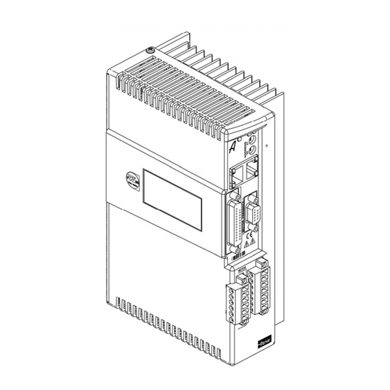
Parker Hannifin Connectors All Aries Controller models have the same set of connectors. Connector specifications are in this section and also “Appendix A Additional Specifications.” Figure 7 shows the name and location of the connectors. Figure 7 Aries Controller Connectors... -
Page 28: Output Power Connector
Parker Hannifin Output Power Connector The drive’s Motor screw terminal connector provides output power to the motor. [For connection information, see Output (Motor) Power on page 27.] The drive’s Motor connector provides terminals U, V, W and for connecting output power to the motor. It also serves to connect an external motor brake to the drive’s internal solid-state relay on the two BK terminals. -
Page 29: Input Power / Mains Connector
Parker Hannifin Input Power / Mains Connector The Input Power / Mains connector contains terminals for external regeneration, control power, and motor power. Do not connect power to this connector before reading the section Power Supply on page 29. The Input Power / Mains connector provides terminals L1, L2, and connecting motor mains power. -
Page 30: Motor Feedback Connector
Manufacturer ........... KYCON or equivalent KYCON Part Number......K66-E15S-NR Motor Feedback Connector Specification—Mating Connector Mating connectors are not provided with the drive. Parker cables are available with mating connectors attached. Connector Type........15-Pin High Density D-Subminiature (male connector) Manufacturer ........... AMP or equivalent... -
Page 31: Table 9 Motor Feedback Connector Pinout
748333-4 Gold Flash—Amp Part Number 748333-7 Important — Encoder inputs use a DS26LV32 differential line receiver. Parker Hannifin recommends 26LS31 (or compatible) differential line driven encoders. Single-ended encoders are not compatible with the drive/controller. Motor Feedback Connector Pinout Pinout configuration for the Motor Feedback connector is listed in Table 9. A box surrounding pins indicates a requirement for twisted pair wiring. -
Page 32: Figure 12 Internal Circuit Diagram For The Motor Feedback Connector
Parker Hannifin Internal Connections A schematic diagram of the internal connections for the Motor Feedback connector is shown in Figure 12. Figure 12 Internal Circuit Diagram for the Motor Feedback Connector Chapter 3 Electrical Installation - 21 -... -
Page 33: Drive I/O Connector
Parker Hannifin Encoder Inputs Encoder input requirements are listed in Table 10. Description Typical Units Common Mode Range Current—Encoder Current—Hall Differential Threshold Voltage -200 +200 Differential Termination ohms Impedance Thermal Switch Current Thermal Switch Voltage Maximum (supplied) Primary Encoder Input Frequency (pre-quadrature) Note: All parameters are at the connector pin. - Page 34 Parker Hannifin KYCON Part Number......K22-B25S-NR Drive I/O Connector Specification—Mating Connector Mating connectors are not provided with the drive. Connector Type........25-Pin D-Subminiature (male connector) Manufacturer ........... AMP or equivalent Cable Kit..........AMP Part Number 748474-1 Includes: 1658648-1 connector, shield, enclosure, and two jack...
-
Page 35: Table 11 Drive I/O Connector Pinout
Parker Hannifin Drive I/O Connector Pinout Pinout configuration for the Drive I/O connector is listed in Table 11. A box surrounding pins indicates a requirement for twisted pair wiring. Signal Input 0+ Input 0– Input 1+ Input 1– Input 2+ Input 2–... -
Page 36: Figure 14 Internal Circuit Diagram For The Drive I/O Connector
Parker Hannifin Internal Connections A schematic diagram of the internal connections for the Drive I/O connector is shown in Figure 14. Figure 14 Internal Circuit Diagram for the Drive I/O Connector Chapter 3 Electrical Installation - 25 -... -
Page 37: Table 12 Inputs-Trigger And Home Electrical/Timing Characteristics
Parker Hannifin Inputs—High-Speed The high-speed inputs are optically isolated inputs. Current is limited internally for input voltage control of 5 to 24 volt logic. The Anode (+) and Cathode (−) optocoupler inputs are on separate connector pins to allow significant flexibility in wiring to different styles of interface. -
Page 38: Output (Motor) Power
Parker Hannifin Outputs—General Purpose The general purpose outputs are optically isolated and current limited. Both sides of the MOSFET output structure are brought to the pins to allow significant flexibility in wiring to different styles of interface. Description Typical Units Turn-on time –... -
Page 39: Output (Motor) Power Connections
Figure 15 Output Power Connection Current Parker motor cables are marked with white numbers (1,2, or 3) to indicate the phase. Connect Motor Phase 1 to U, 2 to V, and 3 to W, and Motor Safety Earth to the Protective Earth ground connector. -
Page 40: Power Supply
Parker Hannifin Power Supply Important — Power to the Aries Controller can be supplied in two ways. Completely read this section and comply with all safety measures before proceeding with connecting the unit to power. Input Power The mains Motor Power supply and the optional Control Power supply for the drive/controller must meet the requirements listed in Table 17. -
Page 41: Drive Inrush Current
Parker Hannifin Control Power Fuse Information Each Control Power input line must be protected by the following fuse: Fuse Rating..........1 Amp Fuse Type ..........Class CC (Bussmann KTK-R-1 or equivalent UL listed fuse) Input Voltage Range ....... 120/240 VAC, 50/60 Hz Input Current ........... -
Page 42: Power Supply Connections
Parker Hannifin Power Supply Connections Power to the Aries Controller may be supplied in one of two ways: a single- source to the Motor Input Power (Mains) screw terminals with the factory- installed jumpers in place; or removal of the jumpers and application of separate sources to the Motor Power terminals and to the Control Power terminals. -
Page 43: Figure 17 Motor And Control Power Supply Connection, Separate Sources
Parker Hannifin Separate Sources Connections Figure 17 shows how to connect separate external Motor and Control Power sources to the terminal connector installed in the drive. Note: You must remove the factory installed jumper wires to use separate power sources. For more information on the jumpers, see Factory Installed Jumpers on page 19. -
Page 44: Multiple Drive/Controller Installations
Figure 18. Under normal operation, no current should flow through the Protective Earth ground. Safety Earth Connection For multiple drive installations, Parker Hannifin recommends a single point or “star” safety earth configuration. Figure 18 represents a typical star safety earth connection . -
Page 45: Brake Relay (Optional)
Parker Hannifin Brake Relay (Optional) The Brake Relay connection (on the Output Power connector) provides a safety feature for your motion control system, particularly for vertical applications. The drive/controller acts as a control switch for the motor brake (if a brake is present). When 24V is applied from an outside power supply through the drive’s Brake Relay (BK) terminals, the motor brake is disabled. -
Page 46: Brake Relay Connection
Brake Relay to Motors with Full Wave Rectifiers Some Parker brake motors (BE, SM, SE, NeoMetric, MPP, and J series motors, serial numbers 010904xxxxx and greater) contain full wave rectifiers, so connection polarity is not an issue during installation. -
Page 47: Figure 20 Brake Relay Connection For Motor With Full Wave Rectifiers
Parker Hannifin Figure 20 shows a typical application. Figure 20 Brake Relay Connection for Motor with Full Wave Rectifiers - 36 - Aries Controller Hardware Installation Guide... -
Page 48: Regeneration Protection
010904xxxxx, or non-Parker motors, you must install a fly-back diode. Consult the specifications or the manufacturer of your motor. 1. Connect one red/blue brake wire (Parker Motor cable or equivalent) to one BK terminal (located on the Motor connector. -
Page 49: Internal Regeneration Capability
Parker Hannifin Figure 22 illustrates the external regeneration resistor connections. Figure 22 External Regeneration Connection Warning — The drive/controller’s connector strip terminals are at hazardous voltages when power is applied, and up to several minutes after power is removed. Lower voltages may still be present for several minutes after power is removed. -
Page 50: Chapter 4 Communications
C H A P T E R F O U R Communications Chapter 4 Communications IN THIS CHAPTER • Overview ..................... 40 • Ethernet Specifications ............... 40 • Assigning IP Address ................42 • Connecting to a PC ................46 •... -
Page 51: Overview
Parker Hannifin Overview The Aries Controller drive communicates in a standard Ethernet network, thereby providing a direct link for sending commands through the ACR-View online help system installed on a PC. This chapter describes how to establish the standard Ethernet connection. -
Page 52: Table 23 Rj-45 Connector Pinout
Parker Hannifin Ethernet Connector Pinout Table 23 contains the Ethernet connector pinout. Signal Wire Color Description White/orange Differential Receive positive side RX– Orange Differential Receive negative side White/green Differential Transmit positive side Blue Not used White/blue Not used TX– Green... -
Page 53: Assigning Ip Addresses
Parker Hannifin Assigning IP Addresses Communication between the Aries Controller and your PC must be set up before connecting over the Ethernet network. Do this by first setting the IP address of the Aries Controller, and then setting the IP address and subnet mask for the PC. -
Page 54: Setting The Ip Address And Subnet Mask-Pc
Parker Hannifin Setting the IP Address and Subnet Mask—PC Now set the IP address and Subnet mask for your PC. (These instructions are for Windows XP users. If you have another Windows version, the steps may vary. Please consult your Network Administrator.) 1. -
Page 55: Figure 27 Internet Protocol (Tcp/Ip) Properties Screen
Parker Hannifin 5. Select Internet Protocol (TCP/IP) and click on the Properties button. You should get a window similar to this: Figure 27 Internet Protocol (TCP/IP) Properties Screen 6. Click on the radio button next to “Use the following IP address:” and type in an IP address with the same first three octets as the default Aries Controller IP address (192.168.100). -
Page 56: Figure 28 Internet Protocol Properties Screen Completed
Parker Hannifin 7. Set the Subnet mask value to 255.255.255.0. Your window should look similar to the following: Figure 28 Internet Protocol Properties Screen Completed 8. Click OK twice to close the windows and save your changes. 9. It might be necessary to reboot your PC before you can connect to the Aries Controller. -
Page 57: Connecting To A Pc
Parker Hannifin Connecting to a PC After assigning the IP address for the Aries Controller, and the Subnet mask and a different IP address for your PC, connect one end of an Ethernet cable to the PC. Connect the other end to one of the Aries Controller’s two RJ-45 socket connectors. -
Page 58: Led Status Indicators
Parker Hannifin LED Status Indicators Ethernet Network Status The drive has one bi-color LED on the left of the front panel that indicates Ethernet status. It displays green or yellow colors. Figure 30 shows the location of the LED on the unit. -
Page 59: Table 26 Drive Status Indicator Led Descriptions
Parker Hannifin Figure 31 Drive/Controller Status Indicator LEDs Drive/Controller Status LED Illumination States LED Left LED Right Description Drive/Controller Enabled Green Enabled Green Yellow (flashes during Enabled, Regeneration active Regeneration) Green Yellow/Green (alternating) Enabled, Autorun mode Drive/Controller Disabled Disabled, no faults or... -
Page 60: Chapter 5 Tuning
CHAPTER FIVE Tuning Chapter 5 Tuning IN THIS CHAPTER • Servo Tuning Overview............... 50 • Position Variable Overview ..............51 • Servo Response Overview..............52 • Servo System Gains ................55 • Servo Tuning—Tutorial ............... 58 • Auto-Tuning..................64... -
Page 61: Servo Tuning Overview
Parker Hannifin Servo Tuning Overview The Aries Controller uses a digital control algorithm to control and maintain position and velocity. The digital control algorithm consists of a set of numerical equations used to periodically (once every servo sampling period) calculate the value of the control output. -
Page 62: Position Variable Overview
Parker Hannifin Position Variable Overview In a servo system, the controller uses two types of position information: commanded position and actual position. As these positions change with time, you can use the position values to determine if the system is positioning as you expect. -
Page 63: Servo Response Overview
Parker Hannifin Even when the system is properly tuned, the position error can still be quite significant due to a combination of factors such as the desired profile, the motor's limitation, or the dynamic characteristics of the system. For example,... -
Page 64: Position Response Types
Parker Hannifin Position Response Types Table 27 identifies the six basic types of position responses. The primary difference among these responses is due to damping—the suppression (or cancellation) of oscillation. Response Description Profile (position/time) Unstable Instability causes the position to oscillate in an exponentially diverging fashion. -
Page 65: Performance Measurements
Parker Hannifin Performance Measurements If you plot of the position response versus time, you can make a few measurements to quantitatively assess the performance of the servo. These three measurements are made before or shortly after the motor stops moving: •... -
Page 66: Servo System Gains
Parker Hannifin Servo System Gains Proportional Feedback Control (PGAIN) Proportional feedback is the most important feedback for stabilizing a servo system. When the controller uses proportional feedback, the control signal is linearly proportional to the position error (the difference between the commanded position and the actual position). -
Page 67: Controlling Integral Windup
Parker Hannifin Controlling Integral Windup If you are using integral control (IGAIN) and there is an appreciable position error that persists long enough during the transient period (time taken to reach the setpoint), the control signal generated by the integral action can end up too high;... -
Page 68: Figure 35 Integrator Windup (Using The Ilimit)
Parker Hannifin The integral windup limit (ILIMIT) command allows you to set the absolute limit of the integral. The commanded limit, in essence, turns off the integral action as soon as it reaches the limit; consequently, position overshoot and oscillation can be reduced (see Figure 35.) -
Page 69: Servo Tuning-Tutorial
IGAIN: Adjusts steady-state errors (not discussed in this tutorial). Adding integral gain also increases responsiveness, though the increase might not be noticeable. Tuning Example The tuning example assumes the following: • Parker BE 241 motor. • 9 to 1 load-to-rotor inertia ratio. Illustration Legend Color Position... - Page 70 Parker Hannifin 1. As a starting point, the PGAIN is set to 0.0003; no DGAIN is set at this time. The following figure shows that the motor is under responsive. 2. The PGAIN is increased to 0.0005 to increase the response. As the next figure illustrates, the motor response increased significantly, the motor is under-damped.
- Page 71 Parker Hannifin 3. Setting the DGAIN to 0.00001 slightly over-damps the response, as shown in the following figure. Now you can return to adjusting the motor response by increasing the PGAIN. If you were to increase the proportional gain without adjusting the derivative gain, the oscillations would increase and possibly create motor instability.
- Page 72 Parker Hannifin 4. With PGAIN increased to 0.001, motor responsiveness has increased and the over-damping has decreased slightly. As there is no significant change to the settling, there is no need to adjust the DGAIN. However, there is still room for improvement on motor response.
- Page 73 Parker Hannifin 6. Increasing the DGAIN to 0.00003 damps the oscillation. As the next figure illustrates, both motor response and damping look good. You are ready to add a load to the motor. 7. With a loaded motor, the response has slowed and the damping is weaker.
- Page 74 Parker Hannifin 8. The PGAIN is increased to 0.02, and you can see better response from the motor. But there is still some oscillation from the motor, so increase the damping. 9. With DGAIN increased to 0.00015, the chattering is significantly reduced—both motor response and damping look good.
-
Page 75: Auto-Tuning
Parker Hannifin Warning — When tuning a servo motor, remove all loads from the motor to prevent personal injury or mechanical destruction. Once tuning provides a stable and responsive servo motor, you can attach the load and start the tuning process again. -
Page 76: Chapter 6 Troubleshooting
CHAPTER SIX Troubleshooting Chapter 6 Troubleshooting IN THIS CHAPTER • General Troubleshooting Guidelines ..........66 • Power ....................66 • Power-Up Sequence ................67 • Communications.................. 67 • Motor Control..................71 • Fault Correction................... 72... -
Page 77: General Troubleshooting Guidelines
Parker Hannifin General Troubleshooting Guidelines The Aries Controller design features easy connectivity, auto-detect functions, and reliability. In addition, LEDs on the front panel of the unit provide quick identification of AC power, drive, and Ethernet status. If, after following the... -
Page 78: Power-Up Sequence
Parker Hannifin Power-Up Sequence Observing the power-up sequence may help identify defective hardware or software issues. Any deviation from the following power-up sequence may indicate the need for additional technical resources. Please see “Technical Assistance” on page ii for contact information. -
Page 79: Ethernet Network Status Led
Parker Hannifin Steady Flash Description Ethernet — No Ethernet link detected Link/Activity Yellow — Ethernet link established, no activity — Yellow Ethernet link established and active Ethernet Speed — Ethernet 10Mbps Green — Ethernet 100Mbps Table 28 Ethernet Status LED Descriptions If neither RJ-45 Ethernet Status LED is illuminated, the physical Ethernet connection is faulty. -
Page 80: Table 29 Ethernet Status Indicator Led Descriptions
Parker Hannifin Ethernet Status LED Illumination States LED State Description Powering up; no connection on port 5002/5006 or 5003 Green TCP connection on port 5002 or 5006 UDP connection on port 5003 Red/Green (alternating) UDP and TCP connection active Table 29 Ethernet Status Indicator LED Descriptions 1. - Page 81 Parker Hannifin ACR-View The ACR-View software is a user-friendly interface for verifying status of and commanding the Aries Controller. Use ACR-View to perform additional troubleshooting of your network and drive/controller. Once you have established an Ethernet connection as indicated by the Ethernet Network Status LED, launch ACR-View on the computer system connected to your drive/controller.
-
Page 82: Motor Control
Parker Hannifin Motor Control The first step in troubleshooting motor-control issues is to examine the Drive/Controller Status LEDs (Figure 39). Use Table 30 to determine the indicated condition. Use the additional information in this section to take corrective action. Figure 39 Drive/Controller Status LEDs... -
Page 83: Fault Correction
Parker Hannifin Drive/Controller Status LED Illumination States LED Left LED Right Description Drive/Controller Enabled Green Enabled Green Yellow (flashes during Enabled, Regeneration active Regeneration) Green Yellow/Green (alternating) Enabled, Autorun mode Drive/Controller Disabled Disabled, no faults or Ethernet boot, 8-second process... -
Page 84: Error Codes
Parker Hannifin Error Codes Table 31 below contains a list of error messages and a brief description of corrective action. Error Resolution The motor rating is too high for the drive/controller, and the Motor Configuration drive/controller is using its own limits for safety reasons. -
Page 85: Drive Configuration
Parker Hannifin Error Resolution Wait for the drive/controller to cool down. E34 Drive Temperature Fault The motor thermal model has determined the motor is too hot. Wait for E35 Motor Thermal Model Fault the motor to cool, and then re-enable the drive/controller. (S21 Transfer Mode Temperature) Motor thermal switch has tripped. -
Page 86: Smart Encoders
3. Apply power to the drive/controller. a. Send the SFB command. It should report 4. If the response is not <*>4, then check the feedback cable (if using a non-Parker cable, check that it is correctly wired). If the cable is correctly wired and connected, the problem might be the encoder. - Page 87 Parker Hannifin 5. Does ?THALL report the Hall state sequence [1, 5, 4, 6, 2, 3, 1...] as the motor turns clockwise? (Clockwise means ?TPE is increasing when Bit 8455 set to zero (Ø); it is also the direction the motor turns in ?DMODE1.)
-
Page 88: Figure 40 Hall Connection Diagram
Parker Hannifin Procedures Procedure 1—Motor Wires Use this procedure to connect your motor wires to the Aries Controller. 1. With the motor’s feedback cable connected to the drive/controller, randomly connect two motor input power wires and slowly apply a positive voltage with respect to the third. See Figure 40 on page 77. -
Page 89: Table 32 Configuring Hall Sensors
Parker Hannifin Procedure 2—Hall Wires Use this procedure to connect your Hall wires to the Aries Controller. 1. First operate the Aries Controller in DMODE1 and verify that the motor turns clockwise. If not, swap any two motor wires. 2. Remove the motor input power leads, leaving the feedback cable connected to the drive/controller. -
Page 90: Figure 41 Motor Terminal Voltages (Back Emf) And Hall Sensor Signals
Parker Hannifin Figure 41 illustrates the alignment of phases U, V, and W with Halls 1, 2, and 3 as viewed from the front of the shaft. The illustration assumes the following: • Hall signals that are High equal signals. -
Page 91: Appendix A Additional Specifications
APPENDIX A Additional Specifications Appendix A Additional Specifications IN THIS CHAPTER • Amplifier ....................81 • Performance..................81 • Protective Circuits ................82 • Cables ....................85... -
Page 92: Amplifier
Parker Hannifin Amplifier Control Power: all models ....... 120/240 VAC Single Phase Mains Control Power AR-04CE, AR-08CE, and AR-13CE ..Single Phase AC Input, 120/240 VAC 16 or 32 kHz switching frequency (motor dependant), pulse-width modulated (PWM) with 3-phase motor output Current Loop Update Rate...... -
Page 93: Protective Circuits
Parker Hannifin Protective Circuits Short Circuit Protection The Aries Controller drive has an internal circuit that protects it from short circuits between one motor terminal to another (phase to phase), or from any motor terminal to earth. Short Circuit Fault—Cause ..... Phase-to-phase short circuit Phase-to-earth short circuit Results of Fault ........ -
Page 94: Under-Voltage Protection
Parker Hannifin Resetting the Fault After the internal temperature has dropped below the values shown in Table 35, you can clear the latched fault. There are two methods available: Cycle power to the drive/controller. –or– Open ACR-View and issue the DRIVE RES AXIS0 command to the Aries Controller. -
Page 95: Over-Voltage Protection
Parker Hannifin Over-Voltage Protection The Aries Controller over-voltage circuit protects the drive from excessive regeneration. If the voltage on the motor output terminals rises above the threshold voltage, the drive/controller issues an over-voltage fault and turns off power to the motor output terminals (Output Power connector). This allows the motor to freewheel to a stop. -
Page 96: Current Foldback
Figure 42 Time Until Current Foldback Occurs Cables EMC Ready Cables Many Parker cables are EMC installation ready. If installed according to instructions provided under A Highly-Immune, Low-Emission Installation— Meeting the Requirements of the Electromagnetic Compatibility (EMC) Directive on page 104, these cables are designed to aid the user in gaining European Compliance, and are thus an integral part of a CE system solution. -
Page 97: Appendix B External Power-Dump Resistor Selection
APPENDIX B External Power Dump Resistor Selection Appendix B External Power-Dump Resistor Selection IN THIS CHAPTER • External Power Dump ................. 87 • Simplified Resistor Selection............... 88 • Calculating Resistance—Rotary Motors ..........89 • Resistor Specifications—Rotary Motors ..........93 • Calculating Resistance—Linear Motors.......... -
Page 98: External Power Dump
There are two methods for selecting the appropriate external power-dump resistor: • In this appendix, the section Simplified Resistor Selection provides quick recommendations for Parker drive and motor combinations. • The sections Resistor Specifications—Rotary Motors and Resistor Specifications—Linear Motors step you through the relevant formulas to determine the needs of your particular application. -
Page 99: Simplified Resistor Selection
Table 38 contains recommended power-dump resistors for specific drive/controller and Parker Hannifin motor combinations. The recommendations are based on the calculations presented in the section Calculating Resistance—Rotary Motors. These recommendations assume a... -
Page 100: Calculating Resistance-Rotary Motors
Parker Hannifin Calculating Resistance—Rotary Motors Because there are different types of motion profiles and application-specific conditions, you may need to modify the results to suit your particular application. To keep it simple, the formulas assume a trapezoidal move profile in which the deceleration event is a single constant deceleration to zero (Ø) velocity. -
Page 101: Energy Absorbed By Drive Capacitors
Parker Hannifin calculate the potential energy that must be absorbed or dissipated elsewhere. Where potential energy (Joules) mass of forcer and load (kg) gravitational constant (9.81 m/s vertical height change during deceleration (m) Energy Absorbed by Drive Capacitors The Aries Controller drive capacitors absorb some of the kinetic and potential energy. -
Page 102: Energy Dissipated In Motor Winding Resistance
Parker Hannifin Energy Dissipated in Motor Winding Resistance Some energy is dissipated in the motor windings. Because the energy is converted to wasted heat in the motor, it is referred to as copper losses. The energy during deceleration can be derived from the inertia, deceleration rate, motor resistance, and motor torque constant. -
Page 103: Energy To Dissipate In The External Power-Dump Resistor
Parker Hannifin Energy to Dissipate in the External Power-Dump Resistor To stop a motor, kinetic and potential energy must go somewhere. Through the previous calculations, you have determined the total kinetic and potential energy, and the energy lost to various paths. -
Page 104: Resistor Specifications-Rotary Motors
Parker Hannifin Resistor Specifications—Rotary Motors Having determined the amount of energy to dump (E ), you can then calculate the resistor specifications. • Maximum resistance • Peak dissipation • Average dissipation Maximum Resistance This calculation determines the maximum value of resistance needed for the external power-dump resistor. - Page 105 Parker Hannifin Peak Dissipation During a single deceleration, all the calculated power-dump energy (E ) must dissipate in the external resistor. The external power-dump resistor then slowly dissipates that energy as heat. This peak power must not exceed the capabilities of the resistor, which is typically 10 times the average power rating.
-
Page 106: Calculating Resistance-Linear Motors
Parker Hannifin Calculating Resistance—Linear Motors Because there are different types of motion profiles and application-specific conditions, you may need to modify the results to suit your particular application. To keep it simple, the formulas assume a trapezoidal move profile in which the deceleration event is a single constant deceleration to zero (Ø) velocity. -
Page 107: Energy Absorbed By Drive Capacitors
Parker Hannifin Where potential energy (Joules) mass of forcer and load (kg) gravitational constant (9.81 m/s vertical height change during deceleration (m) Energy Absorbed by Drive Capacitors The Aries Controller drive capacitors absorb some of the kinetic and potential energy. While the capacitors absorb energy, the bus voltage increases. -
Page 108: Energy Dissipated In Motor Winding Resistance
Parker Hannifin Energy Dissipated in Motor Winding Resistance Some energy is dissipated in the motor windings. Because the energy is converted to wasted heat in the motor, it is referred to as copper losses. The energy during deceleration can be derived from the mass, deceleration rate, motor resistance, and motor force constant. -
Page 109: Energy To Dissipate In The External Power-Dump Resistor
Parker Hannifin Energy to Dissipate in the External Power-Dump Resistor To stop a motor, kinetic and potential energy must go somewhere. Through the previous calculations, you have determined the total kinetic and potential energy, and the energy lost to various paths. - Page 110 Parker Hannifin ⋅ ⋅ TRIP ⋅ Where maximum external power dump resistance (Ohms) voltage across the resistor (V TRIP current through the resistor (drive current required to decelerate the load)(Amps = power dump trip DC voltage (400 VDC) TRIP motor force constant (N/Amp...
- Page 111 Parker Hannifin Where = average power into the external power dump resistor (Watts) = peak power into the external power dump resistor (Watts) PEAK deceleration time (Seconds) cycle time or time between each deceleration event (Seconds) Important — Under normal operation the external power-dump resistor could operate in excess of 200 °C.
-
Page 112: Appendix C Regulatory Compliance-Ul And Ce
APPENDIX C Regulatory Compliance UL and CE Appendix C Regulatory Compliance–UL and CE IN THIS CHAPTER • System Installation Overview ............102 • Regulatory Agencies ................. 111 • Standards of Compliance..............111... -
Page 113: System Installation Overview
It should be stressed that although these recommendations are based on the expertise acquired during the design and development of the drive/controller, and on tests carried out on similar products, it is impossible for Parker to guarantee compliance of any particular installation. This will be strongly influenced by the physical and electrical details of the installation and the performance of other system components. -
Page 114: Installing The Drive/Controller
Parker Hannifin Installing the Drive/Controller Only qualified, skilled electrical technicians familiar with local safety requirements should install this product. For service, the drive/controller must be returned to an authorized service center. There are no user serviceable parts inside the chassis. In certain circumstances, opening the cover may void the product warranty. - Page 115 Parker Hannifin • Drive/Controller Protective Earth Conductor must be connected directly to a reliable system safety Earth point. Total resistance from the drive/controller’s Protective Conductor Terminal to a Reliable System Safety Earth must not exceed 0.1 Ohm, and must be capable of carrying 25A of Fault Current.
-
Page 116: Figure 43 360° Bonding Techniques
Parker Hannifin All braid termination connections must remain secure. For small diameter cables, it may be necessary to fold back the braid or add additional conductive material, such as conductive, adhesive, copper tape to increase the effective diameter of the cable so that R-clamps are secure. -
Page 117: Table 40 Control Power Filter Selection
Filter Manufacturer 6EP1 (160937-5) Corcom 10EP1 (160937-7) Corcom FN2070-10/06 Schaffner 1. Available from Parker: 10 Amp filter—part number 47-016140-01 16 Amp filter—part number 47-017900-01 Table 40 Control Power Filter Selection - 106 – Aries Controller Hardware Installation Guide... -
Page 118: Table 41 Mains Motor Power Filter Selection
Use shielded cabling with braided and bonded headshells. Use of Parker CE/EMC-compliant cables is recommended—they are fully shielded and provide the required screening. Parker cabling requires no additional cable preparation. All motor connections must be made using a high quality braided-screen cable. -
Page 119: Table 42 Ferrite Core Suppressors
Some installations may require that you take additional EMC measures. To further increase product immunity and reduce product emissions, you may add clip-on ferrite absorbers to all cables. Parker recommends ferrites with at least 200 ohm impedance at 100 MHz, such as the... -
Page 120: Figure 44 Typical Lvd/Emc Installation
Parker Hannifin Panel Installation—All Models Figure 44 illustrates a typical panel installation of the drive/controller that meets LVD and EMC requirements. Figure 44 Typical LVD/EMC Installation Warning — This product has been developed for industrial environments. Due to exposed high voltage terminals, this product must not be accessible to users while under normal operation. -
Page 121: Panel Mounting
Parker Hannifin Panel Mounting The mounting clearance requirements are the same for all drive/controller models, as shown in Figure 45. Figure 45 Panel Layout Dimensions - 110 – Aries Controller Hardware Installation Guide... -
Page 122: Regulatory Agencies
Parker Hannifin Regulatory Agencies The Aries Controllers are designed to meet the requirements of global regulatory agencies. The drive/controllers have shown compliance with the regulatory agencies in the following list. The list also shows additional steps that must be taken to ensure compliance. -
Page 123: Appendix D Servo Tuning Flow Diagram
APPENDIX D Servo Tuning Flow Diagram Appendix D Servo Tuning Flow Diagram IN THIS CHAPTER • Servo Tuning Flow Diagram.............. 113... -
Page 124: Servo Tuning Flow Diagram
Parker Hannifin Servo Tuning Flow Diagram Figure 46 Servo Tuning Flow Diagram Appendix D Servo Tuning Flow Diagram - 113 -... -
Page 125: Appendix E Vm25 Expansion Module
Appendix E VM25 Expansion Module A P P E N D I X E VM25 Expansion Module IN THIS CHAPTER • Overview ................... 115... -
Page 126: Overview
Parker Hannifin Overview The VM25 Expansion Module provides screw-terminal connections for I/O on the 25-pin Drive I/O connector. The VM25 comes with a 2-foot cable that provides easy connection between the VM25 and the drive’s 25-pin connector. The VM25 is ordered separately (part number is “VM25”). - Page 127 Control Power............. 30 input resolution ...........78 manufacturers ............ 29 auto-configure, smart encoder ......14, 75 brake relay............34–37 Motor Power (Mains)........... 29 non-Parker motors ..........37 I/O connector ............22 operation ............34 circuit diagram............ 25 Parker motors .............35 pinout ..............24 specification............34...
- Page 128 Parker Hannifin calculating for rotary motor........89 specifications simplified selection ..........88 additional specifications........81 specifications (linear motor) .........98 Brake Relay connector ........34 specifications (rotary motor) ........93 brake relay operation .......... 34 protection Control Power fuse ..........30 current foldback (DIFOLD) ........85 Drive I/O connector ..........
Need help?
Do you have a question about the Aries AR-04CE and is the answer not in the manual?
Questions and answers