Parker Aries AR-04CE Manuals
Manuals and User Guides for Parker Aries AR-04CE. We have 3 Parker Aries AR-04CE manuals available for free PDF download: Hardware Installation Manual, Quick Reference Manual
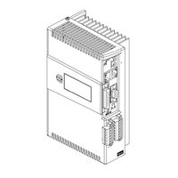
Parker Aries AR-04CE Hardware Installation Manual (129 pages)
Servo Motor Drive
Brand: Parker
|
Category: Controller
|
Size: 4 MB
Table of Contents
Advertisement
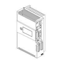
Parker Aries AR-04CE Hardware Installation Manual (129 pages)
Brand: Parker
|
Category: Controller
|
Size: 5 MB
Table of Contents

Parker Aries AR-04CE Quick Reference Manual (2 pages)
Servo Drive/Controllers
Brand: Parker
|
Category: Controller
|
Size: 1 MB
Table of Contents
Advertisement
Advertisement