Table of Contents
Advertisement
Quick Links
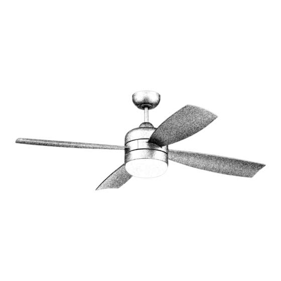
Sebastion
Installation Guide
For Model:
SBN52
WARNING:
DC Motor will not
operate until blades
are installed
4007498
APPROVED FOR USE IN
WET LOCATIONS
net weight of fan: 16.95 lb (7.69 kg)
READ THESE INSTRUCTIONS AND
SAVE THEM FOR FUTURE USE
Table of Contents:
Safety Tips. pg. 3
Unpacking Your Fan. pg. 4
Parts Inventory. pg. 4
Installation Preparation. pg. 5
Hanging Bracket Installation. pg. 5
Fan Assembly. pgs. 6 - 7
Wiring. pg. 8
Canopy Assembly. pg. 9
Blade Assembly. pg. 9
Light Kit Assembly (optional). pg. 10
Remote Control Operation. pg. 12
Smart Ceiling Fan Wi-Fi Control. pg. 13
Testing Your Fan. pg. 14
Troubleshooting. pg. 15
Warranty. pg. 15
page 1
PRINTED IN CHINA
Advertisement
Table of Contents

Related Manuals for Craftmade Sebastion SBN52


Summary of Contents for Craftmade Sebastion SBN52
-
Page 1: Table Of Contents
READ THESE INSTRUCTIONS AND SAVE THEM FOR FUTURE USE Sebastion Installation Guide Table of Contents: For Model: Safety Tips. pg. 3 Unpacking Your Fan. pg. 4 SBN52 Parts Inventory. pg. 4 Installation Preparation. pg. 5 Hanging Bracket Installation. pg. 5 Fan Assembly. - Page 2 Activating Your New Smart Fan; Downloading the Bond Home App • Using your smart device, navigate to the application store (Apple App store or Google Play), download the free Bond Home app and create account. • Ensure the fan and receiver are receiving power from the house supply using the remote control to turn the fan and light ON and OFF.
-
Page 3: Safety Tips
(2) this LED light kit must accept any interference received, including interference that may cause undesired operation. Distributed by: Craftmade, 3901 South 20th Avenue, DFW Airport, TX, 75261; 1-800-486-4892 NOTE: The important safety precautions and instructions appearing in the manual are not meant to cover all possible conditions and situations that may occur. -
Page 4: Unpacking Your Fan
1. Unpacking Your Fan. Carefully open the packaging. Remove items from Styrofoam inserts. Remove motor housing and place on carpet or Styrofoam to avoid damage to finish. Do not discard fan carton or Styrofoam inserts should this fan need to be returned for repairs. Check against parts inventory that all parts have been included. -
Page 5: Installation Preparation
3. Installation Preparation. blade edge To prevent personal injury and damage, ensure that inches the hanging location allows the blades a clearance of (76 cm) 7 feet 7 feet (2.13m) from the floor and 30in. (76cm) from (2.13 m) any wall or obstruction. This fan is suitable for room sizes up to 400 square 12ft. -
Page 6: Fan Assembly. Pgs
5. Fan Assembly. stop pin set screw Remove hanging ball from downrod provided by loosening set screw on hanging ball. Remove pin and clip. Lower hanging ball and remove stop pin. hanging ball Then slide hanging ball off downrod. [Refer to clip diagram 1.] diagram 1... - Page 7 5. Fan Assembly. (cont.) safety cable Remove electrical tape from electrical wiring and weatherproof thread each of the wires, including the safety hanging cable, through a different hole in the ball cover weatherproof hanging ball cover. Pull electrical wiring weatherproof hanging ball cover down securely over hanging ball (on downrod).
-
Page 8: Wiring
6. Wiring. white supply wire WARNING: Turn off circuit breakers to ground (green black supply wire current fixture from breaker panel and be or bare) sure switch is turned to the OFF position. ground (green) CAUTION: Be sure outlet box is properly grounded and that a ground wire (GREEN or blue Bare) is present. -
Page 9: Canopy Assembly
7. Canopy Assembly. hanging bracket Locate 2 screws on underside of hanging bracket and remove screw closest to the open end of the hanging bracket. Partially loosen the other screw. Lift canopy to hanging bracket. Place rounded part of slotted hole in canopy over loosened screw screw canopy in hanging bracket and push up. -
Page 10: Light Kit Assembly (Optional)
9. Light Kit Assembly (optional). motor housing Remove 1 screw from motor plate on underside of motor housing and partially loosen the other 2 screws. Align slotted holes in fitter plate with motor plate loosened screws in motor plate, allowing molex connections from motor housing to come fitter through hole in middle of fitter plate. -
Page 11: Automated Learning Process./Activating Code
10. Automated Learning Process./Activating Code. CAUTION: The remote control transmitter can be programmed to multiple receivers or fans. If this is not desired, turn wall switch off to any other REMOTE CONTROL TRANSMITTER programmable receiver or fan. (back side) Remove battery cover on back side of remote control transmitter. -
Page 12: Remote Control Operation
11. Remote Control Operation. REMOTE CONTROL TRANSMITTER I I I 1--Fan SPEED buttons: Use to control fan speeds 1-6 2--Fan OFF button: Use to turn the fan off 3--REVERSE function button: Use to control direction of fan rotation 4--LIGHT button: Use to control light IMPORTANT: The Automated Learning Process takes approximately 5 minutes to complete. -
Page 13: Smart Ceiling Fan Wi-Fi Control
12. Smart Ceiling Fan Wi-Fi Control. (Optional) Without Wi-Fi activation, you will not enjoy the expanded features and functionality of your ceiling fan: Breeze speed setting, Creating Schedules and Voice Activation. To enjoy all the potential of your new device, refer to the following steps to complete Smart setup. -
Page 14: Testing Your Fan
13. Testing Your Fan. It is recommended that you test fan before finalizing installation. Restore power from circuit box and wall switch (if applicable). Test fan speeds with the different fan speed buttons (I - VI) on remote control transmitter. Test the light ON/OFF function by pressing button;... -
Page 15: Troubleshooting
WARNING: Failure to disconnect power supply prior CRAFTMADE LIMITED LIFETIME WARRANTY: to troubleshooting any wiring issues may result in CRAFTMADE warrants this fan for use as intended under serious injury. the following provision: CRAFTMADE will replace any fan which has faulty performance due to a defect in material Problem: Fan fails to operate.
Need help?
Do you have a question about the Sebastion SBN52 and is the answer not in the manual?
Questions and answers