Table of Contents
Advertisement
Quick Links
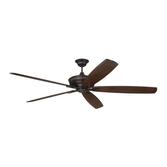
Santori
Installation Guide
For Model:
SNT60
SNT72
WARNING:
DC Motor will not operate
until blades are installed
E192641
net weight of fan: 18.3 lb (8.3 kg), SNT60
19.4 lb (8.8 kg), SNT72
READ THESE INSTRUCTIONS AND
SAVE THEM FOR FUTURE USE
Table of Contents:
Safety Tips. pg. 2
Unpacking Your Fan. pg. 3
Parts Inventory. pg. 3
Installation Preparation. pg. 4
Hanging Bracket Installation. pg. 4
Fan Assembly. pgs. 5 - 6
Wiring. pg. 7
Canopy Assembly. pg. 8
Blade Assembly. pg. 8
Final Installation. pg. 9
Handheld Remote Control Assembly. pg. 10
Remote/Wall Control Operation. pg. 11
Testing Your Fan. pg. 12
Troubleshooting. pg. 13
Warranty. pg. 13
page 1
PRINTED IN CHINA
Advertisement
Table of Contents

Related Manuals for Craftmade Santori SNT60


Summary of Contents for Craftmade Santori SNT60
-
Page 1: Table Of Contents
READ THESE INSTRUCTIONS AND SAVE THEM FOR FUTURE USE Santori Installation Guide For Model: Table of Contents: SNT60 Safety Tips. pg. 2 Unpacking Your Fan. pg. 3 SNT72 Parts Inventory. pg. 3 Installation Preparation. pg. 4 Hanging Bracket Installation. pg. 4 WARNING: Fan Assembly. -
Page 2: Safety Tips
8. Do not use water or detergents when cleaning the fan or fan blades. A dry dust cloth or lightly dampened cloth will be suitable for most cleaning. Distributed by: Craftmade, 3901 S 20 Avenue, DFW Airport, TX, 75261; 1-800-486-4892 NOTE: The important safety precautions and instructions appearing in the manual are not meant to cover all possible conditions and situations that may occur. -
Page 3: Unpacking Your Fan
1. Unpacking Your Fan. Carefully open the packaging. Remove items from Styrofoam inserts. Remove motor housing and place on carpet or Styrofoam to avoid damage to finish. Do not discard fan carton or Styrofoam inserts should this fan need to be returned for repairs. Check against parts inventory that all parts have been included. -
Page 4: Installation Preparation
3. Installation Preparation. blade edge To prevent personal injury and damage, ensure inches that the hanging location allows the blades a 7 feet (2.13 m) (76 cm) clearance of 7 feet (2.13 m) from the floor and 30 in (76 cm) from any wall or obstruction. This fan is suitable for room sizes up to 400 square 12 ft. -
Page 5: Fan Assembly. Pgs
5. Fan Assembly. stop pin set screw Remove hanging ball from downrod provided by loosening set screw on hanging ball. Lower hanging ball and remove stop pin and then slide hanging ball hanging ball off of the downrod. [Refer to diagram 1.] Loosen yoke set screws and nuts at top of motor diagram 1 housing. - Page 6 5. Fan Assembly. (cont.) NOTE: The important safety precautions and instructions appearing in the manual are not meant to cover all possible conditions and safety cable loop wood situations that may occur. It must be ceiling understood that common sense and caution joist are necessary factors in the installation and wood screw...
-
Page 7: Wiring
6. Wiring. white supply wire ground (green black supply wire WARNING: Turn off circuit breakers to current or bare) fixture from breaker panel and be sure switch is ground (green) turned to the OFF position. white CAUTION: Be sure outlet box is properly black grounded and that a ground wire (GREEN or black... -
Page 8: Canopy Assembly
7. Canopy Assembly. Locate 2 screws on underside of hanging bracket and hanging bracket remove screw closest to the open end of the hanging bracket. Partially loosen the other screw. Lift canopy to hanging bracket. Place rounded part of slotted hole in screw canopy over loosened screw in hanging bracket and push up. -
Page 9: Final Installation
9. Final Installation. Remove 3 screws from outer edge of motor switch housing plate (save screws for later housing use). Remove 1 screw from motor plate on underside of motor and partially loosen the other 2 screws. Align slotted holes in center of switch housing plate with molex motor plate... -
Page 10: Handheld Remote Control Assembly
10. Handheld Remote Control Assembly. IN ORDER TO USE THE HANDHELD REMOTE CONTROL, remote control PLEASE CONTINUE WITH SECTION 10 for remote control cover assembly instructions. If you have already installed the wall control but do not wish to use the handheld remote control, please proceed to Section 11. -
Page 11: Automated Learning Process/Activating Code
wall control 11. Automated Learning Process./ Activating Code. I I I CAUTION: The wall and/or handheld remote control can be programmed to multiple receivers or fans. If this is not desired, turn wall switch off to any other programmable receiver or fan. faceplate Restore electrical power and then, if using wall control, set (almond... -
Page 12: Testing Your Fan
13. Testing Your Fan. It is recommended that you test fan before finalizing installation. Restore power from circuit box and wall switch (if applicable). Test wall control (optional III IV installation) by locating ON/OFF slider switch on wall control, then set to the ON position. Test fan speeds. Next, locate handheld remote control. -
Page 13: Troubleshooting
WARNING: Failure to disconnect power CRAFTMADE LIMITED LIFETIME WARRANTY: supply prior to troubleshooting any wiring CRAFTMADE warrants this fan for use as intended issues may result in serious injury. under the following provision: CRAFTMADE will replace any fan which has faulty performance due to a defect in material or workmanship or fails to operate Problem: Fan fails to operate.
Need help?
Do you have a question about the Santori SNT60 and is the answer not in the manual?
Questions and answers