
Related Manuals for OPT7 AURA UNDERGLOW


Summary of Contents for OPT7 AURA UNDERGLOW
- Page 1 AURA UNDERGLOW RV CLASS B/B+ FIT INSTALLATION GUIDE RV Class B : 19~23 ft RV Class B+: 19~24 ft RV Class B : 10 ft RV Class B+: 11 ft AURA HAND HELD REMOTE RV Class B : 7 ft RV Class B+: 8.1 ft...
-
Page 2: Mounting Kit
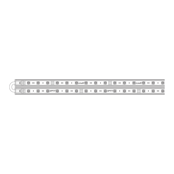
COMPONENTS 8ft EXTENSION WIRE RIGID LIGHT BARS 2×48'' (TWO-SECTION MOVABLE 24") + 8ft EXTENSION WIRE RIGID LIGHT BARS 1×36'' (TWO-SECTION MOVABLE 18") + 8ft EXTENSION WIRE RIGID LIGHT BARS 3×36'' (TWO-SECTION MOVABLE 18") + 1 HARDWIRE POWER HARNESS Y-SPLITTERS AURA HAND HELD REMOTE CONTROL BOX INCLUDES - WIRE MOUNTS, SELF-TAPPING SCREWS, BOOSTER, VELCRO, ZIP TIES... -
Page 3: Control Box
STEP 2 IMPORTANT The control box must be installed inside the vehicle as it Decide where to locate the control box and is not waterproof. Avoid installation areas of the ensure wiring has enough length for light bars to engine bay + heated surfaces . be installed in desired location. - Page 4 EXAMPLES AUXILIARY WIRE FUSE The extension wires are on the led bar. Lay out the bars to measure the length prior to install for a successful installation. 1 x 36” (two-section movable 18") LED Bar + 8ft extension wire 1 x 48” (two-section movable 24") LED Bar + 8ft extension wire 1 x 36”...
- Page 5 IMPORTANT BE SURE TO CONFIRM THE CORRECT DIRECTION OF THE ARROW!! TO AVOID PRODUCT DAMAGE DUE TO INCORRECT INSTALLATION. Flow direction Note the direction of the arrows CORRECT INSTALLATION STEP 3 Secure Control box in desired location with Velcro or zipties. * CONTROL BOX NOT WATERPROOF Ensure the control box is safely and securely hidden from exposing elements of moisture.
- Page 6 85C or 185F. DISCLAIMER OPT7 Lighting is not liable for damages or personal injuries while installing this product. The Installation Guide is intended as assistance to reduce setup time. OPT7 Lighting assumes no responsibility for improper installation.
Need help?
Do you have a question about the AURA UNDERGLOW and is the answer not in the manual?
Questions and answers