
Related Manuals for Endress+Hauser SOP300


Summary of Contents for Endress+Hauser SOP300
- Page 1 Products Solutions Services KA01345S/04/EN/01.17 71372413 Brief Operating Instructions Overfill Prevention System SOP300 For reliable and secure tank overfill prevention...
-
Page 2: Table Of Contents
Performing the functional test ............28 About this document These Brief Operating Instructions describe the commissioning of Overfill Prevention System SOP300 in conjunction with the listed documents. Endress+Hauser... -
Page 3: Symbols Used
Overfill Prevention System SOP300 About this document Symbols used 1.1.1 Safety symbols Symbol Meaning DANGER! DANGER This symbol alerts you to a dangerous situation. Failure to avoid this situation will result in serious or fatal injury. WARNING! This symbol alerts you to a dangerous situation. Failure to avoid this situation can result in WARNING serious or fatal injury. -
Page 4: Text Emphasis
About this document Overfill Prevention System SOP300 1.1.3 Electrical symbols Symbol Meaning Symbol Meaning Direct current Alternating current Direct current and alternating current Ground connection A grounded terminal which, as far as the operator is concerned, is grounded via a grounding system. -
Page 5: Valid Versions
Personnel must meet the following requirements to perform its tasks: ‣ Trained, qualified specialists: must have a relevant qualification for this specific role and task and have been trained by Endress+Hauser. Experts at the Endress+Hauser service organization. ‣ Personnel must be authorized by the plant owner/operator. -
Page 6: Occupational Safety
It meets general safety standards and legal requirements. It also complies with the EC directives listed in the product-specific EC Declaration of Conformity. Endress+Hauser confirms this by affixing the CE mark to the device. -
Page 7: Product Description
Overfill Prevention System SOP300 Product description IT security measures in line with operators' security standards and designed to provide additional protection for the system and system data transfer must be implemented by the operators themselves. The operator is responsible for data backup. - Page 8 Product description Overfill Prevention System SOP300 1 Overview of Manual Overfill Prevention System (MOPS), example Control cabinet for Overfill Prevention System Safety relay output Field signaling siren Field signaling strobe Sensor for High-High alarm Sensor for High warning Actuator to be disabled manually...
- Page 9 Overfill Prevention System SOP300 Product description 2 Overview of Automated Overfill Prevention System (AOPS), example Control cabinet for Overfill Prevention System Safety relay output Sensor for High-High alarm Sensor for High warning Automatically disabled actuator Endress+Hauser...
- Page 10 Product description Overfill Prevention System SOP300 3.1.1 System overview 3 System overview with integrated operating elements (standard) The operating panel is optionally available to order as a separate housing (380 mm x 380 mm x 210 mm). A maximum distance of 100 m is possible between the control cabinet and operating panel.
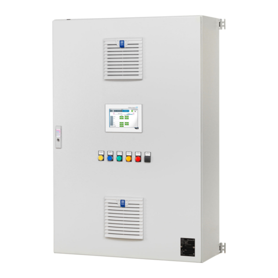
- Page 11 Overfill Prevention System SOP300 Product description 4 Example of control cabinet, exterior view (wall cabinet 1000 mm x 1200 mm x 300 mm) Filter fan Built-in door elements 7" touch display (optional) Air filter Endress+Hauser...
- Page 12 Product description Overfill Prevention System SOP300 5 Example of control cabinet, interior view (wall cabinet 1000 mm x 1200 mm x 300 mm) Power supply Redundant power supply including redundancy module (optional) Optional UPS including button to deactivate battery if no supply voltage is present...
-
Page 13: Incoming Acceptance And Product Identification
Enter serial number): all the information relating to the system/device is then displayed. • Enter the serial number indicated on the nameplate into the Endress+Hauser Operations App, or scan the 2-D matrix code (QR code) on the nameplate using the Endress+Hauser Operations App: all the information relating to the measuring device is then displayed. -
Page 14: Storage And Transport
Installation Overfill Prevention System SOP300 Endress+Hauser Process Solutions AG CH-4153 Reinach Overfill Prevention System Order code: SOP300-12P7/0 Serial number: M9000424450 Ext. order code: SOP300-1AA1A+# Power (nom.): 100...240 V AC 45...65 Hz, 264 VA 01.00.00 01.00.00 +5...+30 °C Made in Switzerland... -
Page 15: Mounting The Control Cabinet
Overfill Prevention System SOP300 Installation CAUTION Leaking battery fluid! Leaking battery fluid can cause skin lesions and poisoning. ‣ Avoid contact with leaking battery fluid. ‣ Do not inhale battery fluid vapors. ‣ Replace faulty batteries immediately. 5.1.1 Control cabinet The following conditions must be met: •... - Page 16 Installation Overfill Prevention System SOP300 1030 6 Example: control cabinet for wall mounting Cabinets for wall mounting are supplied with holders. ‣ Mount the control cabinet on a stable wall using the cabinet holders. 5.2.2 Cabinet for free-standing installation...
- Page 17 Overfill Prevention System SOP300 Installation 1000 7 Example: free-standing cabinet Free-standing cabinets are supplied with a 100 mm base. ‣ Screw the control cabinet onto a secure and even floor. Endress+Hauser...
-
Page 18: Mounting The Field Signalization System
Installation Overfill Prevention System SOP300 Mounting the field signalization system The strobe light and siren must be mounted on a stable and even apparatus using the dimensioned drawings provided below. If possible, the devices should be mounted with the cable glands pointing downwards. -
Page 19: Electrical Connection
Overfill Prevention System SOP300 Electrical connection Is the device adequately protected from precipitation and direct sunlight? Are the securing screws tightened securely? Electrical connection Connection conditions DANGER Electrical voltage! Severe or life-threatening injuries! ‣ Electrical work may only be performed by electrical technicians. -
Page 20: Connecting The System
Supply voltage connection without a redundant power supply in the control cabinet SOP300 Customer side Supply voltage U –1X1 –1X3 9 Supply voltage connection with a redundant power supply in the control cabinet SOP300 – with a redundant supply voltage Customer side Supply voltage U Supply voltage U2 Endress+Hauser... - Page 21 Overfill Prevention System SOP300 Electrical connection –1X1 –1X3 10 Supply voltage connection with a redundant power supply in the control cabinet SOP300 – without a redundant supply voltage Customer side Supply voltage U Bridge at least 2.5 mm , provided by the customer onsite 6.2.2...
- Page 22 Electrical connection Overfill Prevention System SOP300 –1yX1 12 Connection example for point level switches 1 = HH, 2 = H, 3 = L, 4 = LL, 5 = Leak NC or NO contact, depending on the sensor 24 V DC 0 V DC Point level "OK"...
- Page 23 Overfill Prevention System SOP300 Electrical connection –16X1 –16X1 + – + – L+ L– 24VDC 4 to 20 mA 4 to20 mA 2 wire sensor (passive) 4 wire sensor (active) 14 Left: connection example for 2-wire sensor with 4 to 20 mA signal, right: connection example for...
- Page 24 Electrical connection Overfill Prevention System SOP300 –2yX4 Max. 1.5 A N – 15 Connection example for valve control, valve closed without current; alarm relay activated in the "Good" state, change-over contact (1) and NO contact (2) closed 1 = HH, 2 = H, 3 = L, 4 = LL, 5 = Leak...
-
Page 25: Ensuring The Degree Of Protection
Overfill Prevention System SOP300 Electrical connection –20X4 1 Max. 1.5 A N – 16 Connection example for signalization of the system status; system alarm relay activated in the "Good" state, change-over contact (1) and NO contact (2) closed System status is "Good": OK or WARNING... -
Page 26: Post-Connection Check
Operation options Overfill Prevention System SOP300 Ensure that moisture cannot penetrate the cable entry by laying the cable in such a way that it forms a U shape in front of the cable entry (water trap). Seal off any unused cable entries using dummy plugs. -
Page 27: Commissioning
Overfill Prevention System SOP300 Commissioning Commissioning Function check Before commissioning the Overfill Prevention System: Make sure that the post-installation and post-connection checks have been performed: – "Post-installation" checklist, Section 5.3 → 18 – "Post-connection" checklist, Section 6.2 → 26... -
Page 28: Configuring The Overfill Prevention System
Commissioning Overfill Prevention System SOP300 In the case of a redundant power supply Switch on the first circuit breaker. See wiring diagram "+PS1-11F1". Switch on the second circuit breaker. See wiring diagram "+PS1-12F1". Configuring the Overfill Prevention System Log an operator onto the system. The operator must at least have the "Operator" access level. - Page 32 www.addresses.endress.com...
Need help?
Do you have a question about the SOP300 and is the answer not in the manual?
Questions and answers