
Related Manuals for Endress+Hauser OUSAF12


Summary of Contents for Endress+Hauser OUSAF12
- Page 1 Products Solutions Services BA00497C/07/EN/03.21 71538084 2021-07-31 Operating Instructions OUSAF12 Optical sensor combined with the OUA260 flow assembly for absorbance measurement...
- Page 2 Document information OUSAF12 Document information Warnings Structure of information Meaning This symbol alerts you to a dangerous situation. DANGER Failure to avoid the dangerous situation will result in a fatal or serious injury. Causes (/consequences) If necessary, Consequences of non- compliance (if applicable) ‣...
- Page 3 OUSAF12 Basic safety instructions Basic safety instructions Requirements for personnel • Installation, commissioning, operation and maintenance of the measuring system may be carried out only by specially trained technical personnel. • The technical personnel must be authorized by the plant operator to carry out the specified activities.
- Page 4 Basic safety instructions OUSAF12 Operational safety Before commissioning the entire measuring point: Verify that all connections are correct. Ensure that electrical cables and hose connections are undamaged. Do not operate damaged products, and protect them against unintentional operation. Label damaged products as defective.
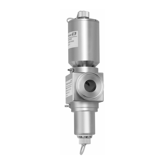
- Page 5 OUSAF12 Product description Product description Sensor design A0014796 1 Sensor with flow assembly OUA260 Cable connector Lamp module Flow assembly OUA260 (depending on version) Detector module The detector and lamp can vary on account of the individual options ordered.
- Page 6 Product description OUSAF12 Measuring principle Light absorption The measuring principle is based on the Lambert-Beer law. There is a linear dependency between the absorption of light and the concentration of the absorbing substance: A = -log(T) = ε T = I/I T ...
- Page 7 OUSAF12 Incoming acceptance and product identification Incoming acceptance and product identification Incoming acceptance Verify that the packaging is undamaged. Notify the supplier of any damage to the packaging. Keep the damaged packaging until the issue has been resolved. Verify that the contents are undamaged.
- Page 8 If you have any queries: Please contact your supplier or local sales center. Installation Installation conditions 5.1.1 Measuring system An optical measuring system comprises: • Sensor (photometer) OUSAF12 • Transmitter, e. g. Liquiline CM44P • Cable set, e. g. CUK80 • Assembly OUA260 Endress+Hauser...
- Page 9 OUSAF12 Installation 3 Example of a measuring system with a photometer sensor Pipe Flow assembly OUA260 Transmitter CM44P Sensor: light source (lamp) CUK80 cable set CUK80 cable set Sensor: detector Endress+Hauser...
- Page 10 Installation OUSAF12 5.1.2 Dimensions A0028304 4 Sensor module Dimension of lamp, depends on lamp type → Table Dimension of detector → Table Assembly, see Technical Information for assembly Lamp type Dimension A in mm (inch) High-luminescence lamp or standardincandescent lamp 33.78 (1.33)
- Page 11 OUSAF12 Installation 5.1.3 Mounting angles A0028250 5 Mounting angles. The arrows indicate the direction of medium flow in the pipe. Suitable mounting angle, better than C Optimum mounting angle, best installation position Acceptable mounting angle Mounting angle to be avoided...
- Page 12 Electrical connection OUSAF12 ‣ Install the sensor upstream from the pressure regulators. ‣ Leave enough room for the cable connector at the end of the lamp and at the end of the detector housing. Unimpeded access to these areas is also required for connection/removal tasks.
- Page 13 The cable set must be ordered separately. ‣ Do not shorten or otherwise modify the CUK80 cable! A0028383 6 OUSAF12 connecting cable Light source (lamp) power supply Signals of detector CM44P terminal Cable color...
- Page 14 Electrical connection OUSAF12 Versions for use in hazardous areas Section applies only to measuring points consisting of a photometer, cable set CUK80 and a Liquiline CM44P transmitter. Safety instructions for electrical apparatus in explosion-hazardous areas, XA01403C 6.3.1 Connecting the detector using a safety barrier The photometer sensors use silicon photovoltaic cells as detectors which are operated in the current mode.
- Page 15 OUSAF12 Electrical connection On delivery, the CUK80 detector cable is permanently wired to the safety barrier. All you have to do is simply connect the individual cable ends to the detector and transmitter. Mount safety barrier including grounding module on a DIN rail.
- Page 16 Electrical connection OUSAF12 EXP-1 Transmitter ATEX II 2G Ex db IIC T5 Gb FM Cl.1, Div. 1, Groups B, C, D A0029440 8 Connecting the hazardous area lamp to CM44P via a junction box Ensuring the degree of protection...
- Page 17 OUSAF12 Electrical connection Post-connection check Device condition and specifications Notes Are the sensor, assembly and cable free from damage on the outside? Visual inspection Electrical connection Notes Does the supply voltage of the connected transmitter match the data on the...
- Page 18 Commissioning OUSAF12 Commissioning Function check Prior to initial commissioning, ensure that: • The sensor is correctly installed • The electrical connection is correct. Calibrating/adjusting the sensor Measuring points consisting of a photometer sensor, flow assembly (if provided) and a transmitter are adjusted at the factory. Normally adjustment is not required when commissioning for the first time.
- Page 19 OUSAF12 Commissioning While the D-tryptophan is dissolving, add deionized water until the beaker contains an approximate volume of 450 ml. Continue stirring at 30 °C (86 °F) until the tryptophan is completely dissolved. Dilute the solution to 1000 ml in a volumetric flask.
- Page 20 Maintenance OUSAF12 It is very important that you use the actual values of the optical Easycal filter. These values are given in the calibration certificate supplied. ‣ Enter the absorbance values (CM44P): Menu/Setup/Inputs/Photometer/Extended setup/Measurement channel/Calib. settings/EasyCal = Yes. Maintenance Take all the necessary precautions in time to ensure the operational safety and reliability of the entire measuring system.
- Page 21 OUSAF12 Maintenance Replacing the gas-filled lamp ‣ Switch off the lamp at the transmitter using the software function. ‣ Remove the lamp cable. ‣ Allow the lamp to cool down (30 minutes). Turn the lamp module counterclockwise to remove it from the flow assembly.
- Page 22 Maintenance OUSAF12 Carefully remove the halogen lamp and the spacer. Check the O-ring and replace it if necessary. Do not touch the lamp with your bare hands. Always use talc-free latex gloves. Clean the new lamp with alcohol and insert it into the fitting with the spacer in- between.
- Page 23 OUSAF12 Maintenance Replacing the standard incandescent or high-luminescence lamp ‣ Switch off the lamp at the transmitter using the software function. ‣ Remove the lamp cable. ‣ Allow the lamp to cool down (30 minutes). Turn the sensor lamp module counterclockwise to remove it from the flow assembly.
- Page 24 Maintenance OUSAF12 Remove the connection, along with the lamp unit, from the lamp housing. To replace the standard incandescent lamp, the entire lamp unit is replaced. Skip the following 3 steps - they only apply for the high-luminescence lamp.
- Page 25 OUSAF12 Maintenance Do not touch the new lamp with your bare hands. Always use talc-free latex gloves. Clean the new lamp with a lint-free cloth. Insert the new lamp into the cover (a). Tighten the securing screws again (b). High-luminescence lamp and standard incandescent lamp Insert the new lamp unit back into the housing and then screw the connection together with the 4 securing screws.
- Page 26 Maintenance OUSAF12 Replacing the collimated incandescent lamp ‣ Switch off the lamp at the transmitter using the software function. ‣ Remove the lamp cable. ‣ Allow the lamp to cool down (30 minutes). Turn the lamp module counterclockwise to remove it from the flow assembly.
- Page 27 OUSAF12 Maintenance Release the 2 securing screws on the optical projection unit (a). Carefully unscrew the optical projection unit (b). Dispose of the lamp unit, along with the cable connector, in accordance with local regulations. Insert the new lamp unit into the optical projection unit and retighten the securing screws.
- Page 28 Maintenance OUSAF12 Insert the re-assembled optical projection unit and lamp unit back into the lamp housing. Install the module fully and fit the 4 screws and washers back on the cable connector. Screw the lamp module back onto the flow assembly by tightening it in the clockwise direction.
- Page 29 OUSAF12 Maintenance The following description applies for both sides, i.e. the detector side and the lamp side. Always change O-rings or optical windows on both sides. Remove the 4 Allen screws (1/8" or 3 mm) from the window ring. Make sure to loosen the screws evenly and alternately around the window ring.
- Page 30 Maintenance OUSAF12 Mount the optical window and then the window ring, along with the new seals, on the assembly. Make sure to tighten the screws of the window ring uniformly in a diagonally opposite sequence. In this way, you ensure that the ring is seated correctly.
- Page 31 OUSAF12 Maintenance A0030205 11 Assembly with POPL function, sectional view Measuring gage Assembly OUA260 Screws of the window ring Path length adjuster Actuators with gaskets Securing screws The following description applies for assemblies with POPL already fitted. If you are retrofitting POPL, please refer to the instructions supplied with the spare parts kit.
- Page 32 The product must be returned if repairs or a factory calibration are required, or if the wrong product was ordered or delivered. As an ISO-certified company and also due to legal regulations, Endress+Hauser is obliged to follow certain procedures when handling any returned products that have been in contact with medium.
- Page 33 (WEEE), the product is marked with the depicted symbol in order to minimize the disposal of WEEE as unsorted municipal waste. Do not dispose of products bearing this marking as unsorted municipal waste. Instead, return them to Endress+Hauser for disposal under the applicable conditions.
- Page 34 Technical data OUSAF12 Technical data 11.1 Input 11.1.1 Measured variable Process-absorption 11.1.2 Measuring range • 0 to 2.5 AU • Max. 50 OD (depending on the optical path length) 11.1.3 Wavelength Broadband, NIR (780 nm+), 400 nm, 420 nm, 430 nm, 540 nm, 950 nm and 1134 nm 11.2...
- Page 35 OUSAF12 Technical data 11.4 Mechanical construction 11.4.1 Dimensions → 10 11.4.2 Weight 1.225 kg (2.7 lbs.), without flow assembly 11.4.3 Materials Sensor housing Stainless steel 316L Assembly OUA260 Technical Information OUA260, TI00418C Assembly CUA261 Operating Instructions CUA261, BA01652C Cable connector ends Nickel-plated brass 11.4.4...
- Page 36 Index OUSAF12 Index Accessories ..... 33 Nameplate ..... . 7 Check Operational safety .
- Page 40 *71538084* 71538084 www.addresses.endress.com...
Need help?
Do you have a question about the OUSAF12 and is the answer not in the manual?
Questions and answers