Endress+Hauser Liquiline Control CDC90 Operating Instructions Manual
Automated cleaning and calibration of memosens sensors
Hide thumbs
Also See for Liquiline Control CDC90:
- Operating instructions manual (118 pages) ,
- Brief operating instructions (76 pages) ,
- Operating instructions manual (108 pages)

Related Manuals for Endress+Hauser Liquiline Control CDC90


Summary of Contents for Endress+Hauser Liquiline Control CDC90
- Page 1 Products Solutions Services BA01707C/07/EN/09.24-00 71666772 2024-07-01 Valid as of version 03.00.00 Operating Instructions Liquiline Control CDC90 Automated cleaning and calibration of Memosens sensors...
-
Page 3: Table Of Contents
Liquiline Control CDC90 Table of contents Table of contents About this document ....4 System integration ....45 Symbols . -
Page 4: About This Document
Documentation The following manuals complement these Operating Instructions and are available on the product pages on the Internet: • Brief Operating Instructions for Liquiline Control CDC90 • Operating Instructions for Memosens, BA01245C • Software description for Memosens inputs • Calibration of Memosens sensors •... -
Page 5: Basic Safety Instructions
Repairs not described in the Operating Instructions provided must be carried out only directly at the manufacturer' s site or by the service organization. Intended use Liquiline Control CDC90 is a fully automatic measuring, cleaning and calibration system for Memosens sensors. 2.2.1... -
Page 6: Product Security
Basic safety instructions Liquiline Control CDC90 Product security 2.5.1 State-of-the-art The product is designed to meet state-of-the-art safety requirements, has been tested, and left the factory in a condition in which it is safe to operate. The relevant regulations and international standards have been observed. -
Page 7: Product Description
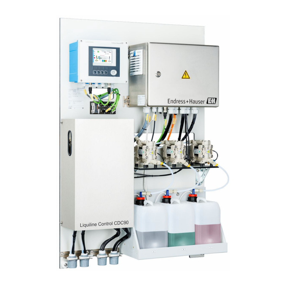
Liquiline Control CDC90 Product description Product description Product design The complete Liquiline Control CDC90 consists of the following components: • CDC90 control unit • Ethernet switch • Pneumatic control unit • Pumps • Canisters for buffer solutions and cleaner • Multihoses for medium control •... - Page 8 Product description Liquiline Control CDC90 3.1.1 Overview of rinsing block A0036050 2 Rinsing block Water connection (hose connector D12 PP) Multihose connection Liquid, pump A Liquid, pump B Liquid, pump C Air rinsing block (pilot valve 4) Outlet rinse connection to assembly 3.1.2...
- Page 9 Liquiline Control CDC90 Product description A0055891 4 CDC90 control unit, inside depending on order version Modules from left to right depending on order version: • Base module BASE2-E • Empty • 2AI module • 2x DIO module • 4AO module (optional, not shown) A0036047 ...
- Page 10 Product description Liquiline Control CDC90 3.1.3 Overview of pneumatic control unit 1-channel The pneumatic control unit controls air, liquids and electricity. The supply voltage is applied here, for example. A0055128 6 Pneumatic control unit for a single channel 100 / 230 VAC terminal...
- Page 11 Liquiline Control CDC90 Product description 2-channel A0055129 7 Pneumatic control unit for 2 channels Extension of the output interface terminals for a 2nd measuring point Extension of the pilot valves for a 2nd channel Endress+Hauser...
-
Page 12: Incoming Acceptance And Product
Incoming acceptance and product identification Liquiline Control CDC90 Incoming acceptance and product identification Incoming acceptance On receipt of the delivery: 1. Check the packaging for damage. Report all damage immediately to the manufacturer. Do not install damaged components. 2. Check the scope of delivery using the delivery note. -
Page 13: Manufacturer Address
Scope of delivery The scope of delivery comprises: Basic version • 1 Liquiline Control CDC90 unit in the version ordered • 1 x Brief Operating Instructions (hard copy) • USB stick for data transmission and backup, software update • Gateway (optional, only for Ethernet/IP, PROFIBUS DP, Profinet version) •... -
Page 14: Mounting
Mounting Liquiline Control CDC90 Mounting Mounting requirements The device is designed for wall mounting or for mounting on a suitable structure, e.g. steel beam. 5.1.1 Installation site Note the following when erecting the device: 1. Make sure that the wall or steel beam has sufficient load-bearing capacity and is fully perpendicular. - Page 15 Liquiline Control CDC90 Mounting 770 (30.31) 8 (0.31) 8 (0.31) 20 (0.79) 86 (3.39) 600 (23.62) A0031946 9 Dimensions of mounting plate. Unit of measurement mm (in) Rinsing block 195 (7.68) 120 (4.72) 5,5 (0.22) Ø 5,5 (0.22) Ø...
-
Page 16: Mounting The System
Mounting Liquiline Control CDC90 Gateway (optional) 113.7 (4.47) 124.5 (4.90) A0056038 11 Gateway dimensions. Unit of measurement mm (in) Mounting the system 5.2.1 Mounting the panel on the wall or steel beam CAUTION Risk of injury The weight of the unit may result in crush injuries or other injuries. - Page 17 Liquiline Control CDC90 Mounting 5.2.2 Connecting the multihoses to the panel Depending on the order code, the multihoses are pre-mounted on the bracket on delivery. The bracket with multihoses still need to be screwed onto the mounting plate. 1. Using the screws provided, secure the bracket of the multihoses to the mounting plate to a torque of 3 Nm.
- Page 18 Mounting Liquiline Control CDC90 3. Guide the coupling of the corrugated hose over the corrugated hose and screw into place. 4. Then push the plug back into the coupling of the corrugated hose and press it firmly into the coupling.
- Page 19 Liquiline Control CDC90 Mounting Rinsing block on rinsing block bracket A0032672 ‣ Secure the rinsing block panel (1) to the rinsing block bracket (2) using the screws (3) and washers (4) provided. 5.2.4 Connecting compressed air and media to the rinsing block Depending on the configuration, a distinction is made between one and two-channel devices and is indicated with a "/ ".
- Page 20 Mounting Liquiline Control CDC90 Assigning individual hoses from the M1/M3 multihose to the rinsing block 3/13 4/14 A/A2 B/B2 C/C2 A0055102 14 Rinsing block, labeling depending on system configuration Water connection Rinse connection outlet to assembly ‣ Connect the individual hoses on the system as follows:...
- Page 21 Liquiline Control CDC90 Mounting 4. Using the clamping ring, secure the hose to the valve by pressing lightly on it. 5. Screw the union nut back onto the valve. The hose is now firmly positioned in the valve. 5.2.5...
- Page 22 Mounting Liquiline Control CDC90 Connecting the individual hoses from the M2/M4 multihose to the assembly A0034130 16 M1 connections on assembly and rinsing block, example with single-channel device 1. Connect hose 1/11 to the connection for moving the assembly in the measure position.
-
Page 23: Mounting The Gateway (Optional)
Liquiline Control CDC90 Mounting 5.2.7 Connecting compressed air supply Compressed air supply When connecting, pay attention to the following: • Hose specifications according to the technical data → 98 • The compressed air line is to be provided by the customer. - Page 24 Mounting Liquiline Control CDC90 2. Verify that the specified installation clearances have been observed. 3. Ensure that the temperature limits are observed at the mounting location. 4. Verify that all hoses are securely mounted and leak-tight. 5. Verify that all multihoses are positioned in such a way that they are protected.
-
Page 25: Electrical Connection
Liquiline Control CDC90 Electrical connection Electrical connection Connecting requirements WARNING Device is live! Incorrect connection may result in injury or death! ‣ The electrical connection may be performed only by an electrical technician. ‣ The electrical technician must have read and understood these Operating Instructions and must follow the instructions contained therein. -
Page 26: Connecting The Cable Shield
Electrical connection Liquiline Control CDC90 Loosen the housing screws crosswise with a PH2 Phillips head screwdriver. ≤ 180° Open the display cover, max. opening angle 180˚ (depends on installation position). 3. To close the housing: tighten the screws in a similar step-by-step, crosswise sequence. -
Page 27: Cable Terminals
Liquiline Control CDC90 Electrical connection 4. Pull the cable through the gland and into the housing. 5. Route the cable in the housing in such a way that the exposed cable shield fits into one of the cable clamps and the cable cores can be easily routed as far as the connection plug on the electronics module. -
Page 28: Connecting The Communication
Electrical connection Liquiline Control CDC90 A0033455 ‣ Guide the sensor cable of the 1st measuring point through cable gland "6" provided. Cable gland "7" is provided for the sensor of the 2nd measuring point. Connecting the sensor cable ‣ Sensor cable connected directly Connect the sensor cable to the terminal connector of the BASE2-E module. -
Page 29: Connecting Analog Communication
Liquiline Control CDC90 Electrical connection Connecting analog communication WARNING Module not covered No shock protection. Danger of electric shock! ‣ Only the 4AO module can be retrofitted at slot 7. Other hardware must not be modified. 1. If additional shields are required, connect them with PE centrally in the control cabinet via terminal blocks supplied by the customer. -
Page 30: Connecting Fieldbus Communication
Electrical connection Liquiline Control CDC90 Measured value transmission Measured values are transmitted from the measuring point to the control system via the optional analog current output module. The analog outputs are configured via the CDC90 control unit. To do this, either access the internal control module via the web server (BA01225C) or using an optionally available external display. - Page 31 Liquiline Control CDC90 Electrical connection RJ45 assignment to M12 connection RJ45 Yellow White Orange Blue Connection of PROFINET and PROFIBUS DP via gateway The gateway must be installed externally. A 3 m (3.28 ft) Ethernet cable is provided. The cable to the process control system must be provided by the customer.
-
Page 32: Connecting Digital Communication
The wiring of external inputs and outputs, such as a flowmeter for example, is carried out on the remote IO/DIO (1) in the pneumatic control unit. These external inputs and outputs can be evaluated during program configuration and activated or deactivated. The configuration must be carried out by Endress+Hauser specialist staff. Endress+Hauser... - Page 33 Liquiline Control CDC90 Electrical connection A0055123 25 Remote IO/DIO in the pneumatic control unit Remote IO/DIO 1. Guide the cables through the cable gland at the bottom of the pneumatic control unit. 2. Wire the cables to the desired terminal on the remote IO/DIO (1). The terminals on...
-
Page 34: Connecting The Position Indicators Of The Assemblies
Electrical connection Liquiline Control CDC90 Function Assignment Assembly 1 Service = 0 Measure = 1 Assembly 2 Service = 0 Measure = 1 Program status No program = 1 Program running = 0 Error status Alarm = 0 No alarm = 1... - Page 35 Liquiline Control CDC90 Electrical connection Monitoring of assembly position A0032747 28 Assembly postion feedback CPA472D 1. Guide the cables for confirmation of position through the cable gland at the bottom of the pneumatic control unit. 2. Wire the cables to the output interface terminal. The terminals at the output...
- Page 36 Electrical connection Liquiline Control CDC90 Monitoring of assembly position A0033325 29 Compressed air control CPA473/474 ‣ Attach the connections for confirmation of position in the pneumatic control unit as follows: Connections on the output interface terminal in the pneumatic control unit...
- Page 37 Liquiline Control CDC90 Electrical connection 6.8.3 Cleanfit CPA87x Assembly monitoring A0032753 30 Position feedback signal, CPA87x W2 Feedback cable A0017831 Limit position switch, service position Limit position switch, measure position Connector, M12, solder side (inside of assembly) Coding Connector, pin side (outside of assembly) A0022163 ...
-
Page 38: Connecting The Main Supply Voltage
Electrical connection Liquiline Control CDC90 The connections on the output interface terminal in the pneumatic control unit for single- channel device Output interface terminal T1, Cable wire Function bottom Pin 1 W2, BK Limit position switch, confirmation of position Pin 2... - Page 39 Liquiline Control CDC90 Electrical connection Connecting the main supply voltage A0033429 Guide the cable of the main supply voltage through cable gland "3" of the pneumatic control unit. A0055125 Connect the wires to the actuator terminal (1) as follows: PE PE...
-
Page 40: Connecting The Gateway (Optional)
Electrical connection Liquiline Control CDC90 6.10 Connecting the gateway (optional) Connecting the power supply to the gateway The power supply to the gateway is provided on site by the customer. See the manufacturer' s documentation. ‣ Assign the 2.5mm² 2-pin terminal block for the power supply at the top of the... -
Page 41: Post-Connection Check
Liquiline Control CDC90 Electrical connection 6.12 Post-connection check WARNING Connection errors The safety of people and of the measuring point is at risk! The manufacturer does not accept any responsibility for errors that result from failure to comply with the instructions in this manual. -
Page 42: Operation Options
Operation options Liquiline Control CDC90 Operation options Overview of operation options 7.1.1 Display and operating elements A0031833 33 Overview of operation Touchscreen display Status LED Soft keys (function selectable) Status according to NAMUR Category Description LED status NAMUR category F F (Failure): No programs are started until it is fixed. -
Page 43: Access To Operating Menu Via Local Display
Liquiline Control CDC90 Operation options Access to operating menu via local display 7.2.1 Operation concept A0033711 34 Touchscreen display The CDC90 can be operated via a touchscreen display. Soft keys are also available for program operation. 7.2.2 Soft keys You can start programs with the soft keys. -
Page 44: Access To The Operating Menu Via The Web Server
Operation options Liquiline Control CDC90 Item Function For one measuring point: • pH sensor: Temperature in °C • ORP sensor: Or ORP value in mV • Combined pH/ORP sensor: Temperature in °C For two measuring points: Navigation to measuring point 2 and display of: •... -
Page 45: System Integration
Liquiline Control CDC90 System integration System integration Integrating the measuring instrument in the system The device can be integrated into the control system by means of the following options: • Web server • Fieldbus systems 8.1.1 Web server The web server enables full access to the visualization of the CDC90. When the web server is active, on-site visualization at the CDC90 is disabled. -
Page 46: Fieldbus Systems
System integration Liquiline Control CDC90 2. Start the PC. 3. Start the Internet browser. 4. If you use a proxy server to connect to the Internet: Disable the proxy (browser settings under "Connections/LAN settings"). 5. Enter the IP address of your device in the address line. Pay attention to the ending of the address (in the example: 192.168.0.4). -
Page 47: Commissioning
Liquiline Control CDC90 Commissioning Commissioning Preliminaries WARNING Incorrect connection, incorrect supply voltage Safety risks for staff and device malfunctions! ‣ Check that all connections have been established correctly in accordance with the wiring diagram. ‣ Ensure that the supply voltage matches the voltage indicated on the nameplate. -
Page 48: Post-Installation And Function Check
Commissioning Liquiline Control CDC90 Post-installation and function check Put the device into operation only if you can answer yes to all the following questions: 1. Is the device securely mounted and installed? 2. Have all the hose systems been correctly implemented according to the plans? 3. -
Page 49: Start Screen
Liquiline Control CDC90 Commissioning 9.3.1 Start screen A0055431 35 Start screen Item Function Header with time, status and measured value display User guidance Measure or service position of assembly Next page Visualization of measuring point 2 Display of pumps for canisters 1-3 Valve (water or air) closed or open. - Page 50 Commissioning Liquiline Control CDC90 → 55 ‣ Change the Date and Time under: System/Setup/Date and Time ‣ Click directly on the time. It can take a few seconds for the setting to be accepted. The device does not support automatic summer/wintertime changeover. These settings can be made manually in the software, e.g.
- Page 51 The current outputs for transmitting measured values on an additional analog card can only be configured with an external display or via the web server of an external transmitter. The current outputs are configured during initial commissioning by Endress+Hauser specialist staff. 9.4.6 Configuring the sensor type The device is preconfigured for the use of pH glass sensors.
- Page 52 Commissioning Liquiline Control CDC90 → 55 Path: System/Information/Sensor Function Options Info Channel 1 or Channel 2 Sensor 1 or Sensor 2 List of sensor-specific information • Sensor type • Serial number: • Measuring point • Hardwareversion • Software version •...
-
Page 53: Calibrating The Sensor
CDC90 logbook. • An additional calibration is not required in many standard applications. ‣ Calibrate sensors at sensible intervals depending on the process. Operating Instructions "Memosens", BA01245C 9.4.11 Starting commissioning Initial commissioning is performed by Endress+Hauser specialists. Endress+Hauser... -
Page 54: Adapting The Measuring Instrument To The Process Conditions
Operation Liquiline Control CDC90 Operation CAUTION Very loud pumps The noise from the pumps can hurt the ears. ‣ Wear ear protectors in the vicinity of the pumps. 10.1 Reading off measured values A0055432 36 Overview of measuring points... -
Page 55: Configuring Users
Liquiline Control CDC90 Operation User management Operator Maintenance Admin User Switch user management Read only rights on and off to system (cannot make Change own password any settings apart from Change all passwords changing the Change the operation language) mode... - Page 56 10.2.3 The structure of the cleaning and calibration programs The cleaning and calibration program is configured via the local display. Customer-specific programs can be created by Endress+Hauser specialist staff. Programs are divided into steps, sequences and programs. Steps • Certain actions concerning sensor cleaning and/or calibration are divided into individual steps.
- Page 57 Liquiline Control CDC90 Operation 10.2.4 Cleaning and calibration steps List of steps for cleaning The device contains preconfigured steps: Name Function Service Position Sets the valves of the implicit channel to move the sensor to the service position. End condition: the step ends when it is possible to detect that the service position has been reached.
- Page 58 Operation Liquiline Control CDC90 Name Function Liquid Pump A Pumps the medium out of canister 1 for the time indicated. Liquid Pump B Pumps the medium out of canister 2 for the time indicated. Liquid Pump C Pumps the medium out of canister 3 for the time indicated.
- Page 59 Liquiline Control CDC90 Operation All sequences can be modified/optimized and reused within sequences. Sequence list for calibration Overview of sequences for devices with calibration function Name Function Sequences with IDs 1001-1008 contain preconfigured basic functions 1001 Service The assembly moves to the service position.
- Page 60 All sequences can be modified/optimized and reused within sequences. Default buffer 1 is Endress+Hauser' s pH 7 buffer. Default buffer 2 is Endress+Hauser' s pH 4 buffer. Please contact Endress+Hauser specialist staff to adapt the calibration buffers. Editing and creating sequences User role: Maintenance Operation mode: Setup →...
- Page 61 Liquiline Control CDC90 Operation Overview of programs for two-channel devices with cleaning function Program name Sequence name Channel Function Programs with IDs 801-806 include preconfigured programs Service1 1001 - Service The assembly of channel 1 moves to the service position...
- Page 62 Operation Liquiline Control CDC90 Program name Sequence name Channel Function 1Pt ORP ADJ1 1013 - 1 Pt ORP ADI Channel 1 performs a program one-point adjustment of an ORP sensor. 1Pt ORP CAL1 1014 - 1 Pt ORP CAL Channel 1 performs a...
-
Page 63: Editing Programs
Liquiline Control CDC90 Operation Program name Sequence name Channel Function 1Pt ORP ADJ2 1013 - 1 Pt ORP ADI Channel 2 performs a program one-point adjustment of an ORP sensor. 1Pt ORP CAL1 1014 - 1 Pt ORP CAL Channel 1 performs a... - Page 64 Operation Liquiline Control CDC90 10.2.7 Schedules Schedules for devices with cleaning function You can assign a schedule to the programs; the program is then executed automatically at a defined frequency based on this schedule. The following schedules are already preconfigured on delivery.
-
Page 65: Creating Schedules
10.2.8 Assigning programs to soft keys The configuration of the soft keys is carried out by Endress+Hauser as part of the commissioning phase. Programs can be assigned to the soft keys of the CDC90 control unit in order to quickly start the programs manually without calling up User Guidance. - Page 66 Operation Liquiline Control CDC90 IDs 801-804 are preassigned for the soft keys. If the programs for the IDs are changed, so too does the assignment of the soft keys. If the program sequence is changed, this affects the assignment of the program to the soft key.
-
Page 67: Exporting Csv Files
Liquiline Control CDC90 Operation Digital input Program Soft key ID801 Service1 ID802 Measure1 ID803 Service2 ID804 Measure2 Starting the program via the soft keys ‣ Press the soft key for 3 seconds until the program starts. 10.2.10 Creation of autostart programs An autostart program makes it possible to create a program that is automatically executed following a failure or reboot. -
Page 68: Exporting The Configuration
Operation Liquiline Control CDC90 Operation mode: Setup → 55 The following files can be exported: Programs csv files System configuration Data for system configuration, e.g. serial number. System configuration is specific for every device. Device configuration Settings, e.g. warning limits, for the devices... -
Page 69: Diagnostics And Troubleshooting
Liquiline Control CDC90 Diagnostics and troubleshooting Diagnostics and troubleshooting 11.1 General troubleshooting 11.1.1 Monitoring inputs and outputs User role: Maintenance Operation mode: Setup → 55 ‣ Open the following menu to monitor or troubleshoot the inputs and outputs: Application/In-/Outputs. -
Page 70: Digital Outputs
Diagnostics and troubleshooting Liquiline Control CDC90 11.1.2 Simulating the inputs and outputs NOTICE The simulation of valves and outputs can cause the assembly to move or data transmission. ‣ Ensure safe operation. For test purposes, the individual pilot valves and outputs can be simulated (enabled), e.g.: •... - Page 71 Liquiline Control CDC90 Diagnostics and troubleshooting • State • Date and time of Message appears • Date and time of Message disappears 11.2.2 Device-specific, general diagnostic messages Namur status Error number Error message Troubleshooting F Failure 1000 Communication between the controller and pilot valve manifold is interrupted ‣...
- Page 72 Diagnostics and troubleshooting Liquiline Control CDC90 Namur status Error number Error message Troubleshooting M Maintenance 1306 Number of switching operations of valve 9 (valves channel 1) is exceeded. S Out of Spec 1400 Error in program file. Invalid program loaded. E.g.: Program for channel 2 although it is a single-channel device.
- Page 73 Liquiline Control CDC90 Diagnostics and troubleshooting Namur status Error number Error message Troubleshooting C Function check Hold active Output values and status of the channel are on hold. F Failure Sensor check No measurement signal from sensor Check sensor connection.
- Page 74 Diagnostics and troubleshooting Liquiline Control CDC90 Namur status Error number Error message Troubleshooting ‣ C Function check Calibration active Wait for calibration to be finished. F Failure Sensor reference Reference warning, impedance of reference too low M Maintenance Sensor reference Measuring can continue until the alarm (120) occurs.
- Page 75 Liquiline Control CDC90 Diagnostics and troubleshooting Namur status Error number Error message Troubleshooting M Maintenance Operating time Operating hours > 100 °C (212°F), measurement can still take place Replace the sensor. Change monitoring limit. Disable monitoring. M Maintenance Operating time...
- Page 76 Diagnostics and troubleshooting Liquiline Control CDC90 Namur status Error number Error message Troubleshooting M Maintenance Sensor calibration Max. slope warning, measurement can still take place. Possible reasons: sensor old or defective, reference blocked, calibration solution too old or contaminated. Check or replace sensor.
-
Page 77: Event Logbook
Liquiline Control CDC90 Diagnostics and troubleshooting Namur status Error number Error message Troubleshooting M Maintenance Sensor calibration Delta operating point warning, measurement can still take place. Possible reasons: sensor old or defective, reference blocked, calibration solution too old or contaminated. -
Page 78: Resetting The Measuring Instrument
• Short description • Time stamp • Measuring point affected • Status of the message 11.4 Resetting the measuring instrument ‣ Contact Endress+Hauser specialist staff to reset the device. 11.5 Firmware history Version Changes to firmware Date 03.00.00 Extension: 01.08.2024 Implementation of a second rinsing block for 2nd measuring point. - Page 79 Liquiline Control CDC90 Diagnostics and troubleshooting Version Changes to firmware Date 02.01.01 Improvement: 28.05.2021 • Programs are started automatically in "Automatic" operation mode after 5 days. • The preview list of the programs shows a vast amount of time remaining (over 40 days).
-
Page 80: Maintenance
Maintenance Liquiline Control CDC90 Maintenance CAUTION Programs not switched off during maintenance activities. Risk of injury due to medium or cleaning agent! ‣ Quit any programs that are active. ‣ If testing the cleaning function while cleaning is in progress, wear protective clothing, goggles and gloves or take other suitable measures to protect yourself. -
Page 81: Maintenance Intervals
Liquiline Control CDC90 Maintenance 12.1 Maintenance intervals Weekly Annually Verify the leak-tight condition of Check if interior is clean, dry and free from corrosion. compressed air connections on: • Clean and dry the interior area. • Pilot valves • Verify that seals, couplings and pumps are leak-tight and •... -
Page 82: Clean Sensor
Maintenance Liquiline Control CDC90 3. Install the new sensor. The sensor data are automatically accepted by the transmitter. A release code is not required. Measurement is resumed. 4. Take the used sensor back to the laboratory. In the laboratory get the sensor ready for reuse while ensuring the availability of the measuring point. -
Page 83: Maintenance Tasks
Liquiline Control CDC90 Maintenance 12.2.3 Canister If the canister is empty, proceed as follows: 1. Loosen the bracket on the inlet side of the pump so that the canister can be replaced. 2. Unscrew and remove the float switch. 3. Fill the empty canister or replace it with a full canister. Use a funnel when filling the canister. - Page 84 Maintenance Liquiline Control CDC90 A0055094 1. Guide the hoses through the opening of the multihose bracket on the panel. 2. Use the counterpart to secure the cable gland. M3 M4 M1 M2 A0055095 Mount the multihoses depending on the configuration: From left to right: position 1...
-
Page 85: Repair
The product must be returned if repairs or a factory calibration are required, or if the wrong product was ordered or delivered. As an ISO-certified company and also due to legal regulations, Endress+Hauser is obliged to follow certain procedures when handling any returned products that have been in contact with medium. -
Page 86: Accessories
Accessories Liquiline Control CDC90 Accessories The following are the most important accessories available at the time this documentation was issued. Listed accessories are technically compatible with the product in the instructions. 1. Application-specific restrictions of the product combination are possible. -
Page 87: Sensors
Liquiline Control CDC90 Accessories 14.2 Sensors 14.2.1 Glass electrodes Memosens CPS11E • pH sensor for standard applications in process and environmental engineering • Digital with Memosens 2.0 technology • Product Configurator on the product page: www.endress.com/cps11e Technical Information TI01493C Memosens CPS31E •... - Page 88 Accessories Liquiline Control CDC90 Memosens CPS92E • ORP sensor for use in heavily polluted media • Digital with Memosens 2.0 technology • Product Configurator on the product page: www.endress.com/cps92e Technical Information TI01577C 14.2.3 pH ISFET sensors Memosens CPS47E • ISFET sensor for pH measurement •...
-
Page 89: Additional Functionality
Liquiline Control CDC90 Accessories 14.3 Additional functionality 14.3.1 Hardware extension modules Kit, extension module 4AO • 4 x analog output 0/4 to 20 mA • Order number: 71135633 14.4 Other accessories 14.4.1 Cable Memosens data cable CYK10 • For digital sensors with Memosens technology •... -
Page 90: Buffer Solutions
• Order number: 71185296 14.4.5 Buffer solutions High-quality buffer solutions from Endress+Hauser - CPY20 Solutions that are produced in the production laboratory and bottled for testing in the calibration laboratory are used as secondary reference buffer solutions. This test is carried out on a partial sample in accordance with the requirements of ISO 17025. -
Page 91: Technical Data
Liquiline Control CDC90 Technical data Technical data 15.1 Input Measured variables → Documentation of the connected sensor Measuring ranges → Documentation of the connected sensor Types of input • Digital sensor inputs for sensors with Memosens protocol (Base-E module in the CDC90 control unit ) •... - Page 92 Technical data Liquiline Control CDC90 Cable specification Max. 2.5 mm (14 AWG) Digital inputs, passive in Span the pneumatic control unit • High: 11 to 30 V DC • Low: 0 to 5 V DC Nominal input current max. 8 mA Cable specification Max.
-
Page 93: Output
Liquiline Control CDC90 Technical data 15.2 Output Output types • Analog outputs, on the Base-E module, active in the CDC90 control unit • Digital outputs, on the External Remote IO, DIO, active in the pneumatic control unit Analog outputs, active in... - Page 94 Technical data Liquiline Control CDC90 Protocol-specific data IPC output signals Modbus TCP EtherNet/IP (via PROFIBUS DP PROFINET (via gateway) (via gateway) gateway) Signal encoding IEEE 802.3 (Ethernet) IEEE 802.3 PROFIBUS-DP- IEEE 802.3 (Ethernet) compliant as per (Ethernet), IEC IEC 61158...
-
Page 95: Power Supply
Liquiline Control CDC90 Technical data 15.3 Power supply Supply voltage 100 to 230 V AC Fluctuations in the mains voltage may not exceed ± 10 percent of the nominal voltage. Frequency 50/60 Hz Power consumption Max. 50 VA Cable specification... -
Page 96: Performance Characteristics
Technical data Liquiline Control CDC90 15.4 Performance characteristics Response time Current outputs = max. 500 ms for an increase from 0 to 20 mA Current inputs = max. 330 ms for an increase from 0 to 20 mA Digital inputs and outputs = max. -
Page 97: Environment
Liquiline Control CDC90 Technical data 15.6 Environment Operate the system only using liquids with a conductivity of > 10 nS/cm. This device may only be used indoors. Ambient temperature 0 to 45˚C (32 to 113˚F) range Storage temperature –20 to 70 °C (–4 to 158 °F) - Page 98 Technical data Liquiline Control CDC90 Materials Device Material CDC90 control unit Module housing PC (polycarbonate) Soft keys TPE (thermoplastic elastomers) Cable mounting rail Stainless steel 1.4301 (AISI 304) Display glass Plastic capacitive touchscreen Cable glands PA (polyamide) V0 as per UL94...
- Page 99 Liquiline Control CDC90 Technical data Pressure switch: Max. 12 bar (174 psi) Pump Vacuum pump: Max. 6 bar (87 psi) (6 bar corresponds to 6 l/min delivery rate, depending on the control air) Lines Max. 10 bar (145 psi) Operating air pressure Max.
-
Page 100: Index
Index Liquiline Control CDC90 Index Housing ........25 Accessories . - Page 101 Liquiline Control CDC90 Index Relative humidity ......97 Repair ........85 Requirements for the personnel .
- Page 102 *71666772* 71666772 www.addresses.endress.com...
Need help?
Do you have a question about the Liquiline Control CDC90 and is the answer not in the manual?
Questions and answers