Table of Contents
Advertisement
Quick Links
Advertisement
Table of Contents

Related Manuals for Rocker Buller 600


Summary of Contents for Rocker Buller 600
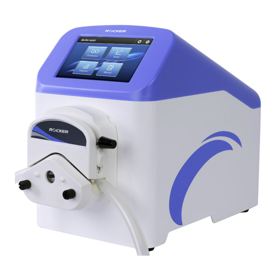
- Page 1 Dispensing Peristaltic Pump Buller 600...
-
Page 3: Table Of Contents
Table of Contents 1. Important Notice ......................... 1 2. Unpacking ............................. 3 3. Main Part Diagram........................4 4. Installation ............................. 5 (1) Power Supply ..........................5 (2) Installation and Operation of Pump Head ................5 (3) Technical Data of Tubing ......................6 (4) Dispenser and Foot Switch Connection .................. -
Page 4: Important Notice
1. Important Notice This instrument is designed for laboratory usage only. Please read this manual carefully before installing and operating. The instrument shall not be modified in any way. Any modification will void the warranty and may result in potential hazard. We are not responsible for any injury or damage caused by any non-intended purposes and modifying the instrument without authorization. - Page 5 Do NOT start the system with the pump head open. Please turn off and unplug the instrument before replacing the fuse. * When handling hazardous chemical and biological solutions, take all appropriate protective measures. * Before operation, please check whether the compatibility of contact materials of instrument with sample solution.
-
Page 6: Unpacking
If there is any problem, please keep the serial number along with packing case and contact your local distributor immediately for assistance. Model Standard Package Includes: Buller 600, Dispensing Peristaltic Pump Silicone Tube Buller 600 Power Cord Instruction Manual... -
Page 7: Main Part Diagram
3. Main Part Diagram Item Designation Item Designation 5” Touch Screen AC Socket and Fuse Holder Normal Flow Rate Pump Head RS232 Signal Port (DB9F) Power Switch... -
Page 8: Installation
4. Installation Power Supply Please connect the instrument to the correct power source as indicated by the rated voltage on the instrument and ensure that there are no flammable materials around the instrument. Installation and Operation of Pump Head Norm. Flow Rate High Flow Rate Pump Head Pump Head... -
Page 9: Technical Data Of Tubing
Disassemble Loose the screws, remove Rotate the pump head counter- them from the pump head. clockwise to remove the pump Remove the pump head from head. the instrument directly. Remove the adaptor if needed. Installation Rotate lever counter- Pull up the flip cover to open tubing clockwise to open the pump the pump head. -
Page 10: Dispenser And Foot Switch Connection
Pump tubing may rupture due to continuous contact with moving parts; it is advisable to replace it according to the tubing manufactures’ replacement interval. Dispenser and Foot Switch Connection DB9M Cable Connection Please connect the DB9M cable from the handling dispenser or foot switch to the RS232 signal port (DB9F) which is located at the back of the instrument. -
Page 11: Configure Of Db9F
Configure of DB9F To use the pump and to monitor the status of pump, Buller 600 adopts a DB9 female connecter (DB9F) at the back of main unit. The configure of DB9F is shown as below. Terminal Declaration 4-20mA Input... -
Page 12: Control Panel
5. Control Panel Homepage Item Designation Description Continuous Setting flow rate or rpm for continuous dispensing. Microbial Build-in frequently used dispensing volume in microbial tests. Dispensing based on dispensing volume, dispensing time, Dispense interval time and dispensing dosages. Build customized dispensing program with multi-functions, Manual including constant, ramp, dispense, interval and cycle. -
Page 13: Functional Buttons
(2) Functional Buttons Item Valid Invalid Description • Back to Homepage • Return to previous page • Setting • Calibration • Start • Pause • Stop • Prime / Stop Prime • Direction (Clockwise / Counterclockwise) • Lock Screen • Add Step •... -
Page 14: Calibration
(3) Calibration Please calibrate before use. This calibration method is volume calibration, please prepare a cylinder for volume measurement. When a volume discrepancy beyond the permissible range is identified during use, calibration should be performed. Click in each mode to perform the calibration. Calibration Page Instruction... - Page 15 Item Designation Description Click to exchange the pump head. Pump Head Norm. FR: Normal Flow Rate Pump Head; High FR: High Flow Rate Pump Head Tubing Click to exchange for different tubing. (16#, 25#, 17#) The instrument will calculate automatically based on Flow Rate dispensing time and dispensing volume.
-
Page 16: Setting
(4) Setting Click to enter the setting page. Designation Description Click for different level of brightness (20%, 40%, 60%, 80%, Brightness 100%). Sound Turn ON / OFF the sound. Turn ON / OFF the Eco mode. Language English / Chinese Back Suction Click to set the back suction time (0.0, 0.3, 0.4, 0.5, 0.6 sec). -
Page 17: Control Mode
(5) Control Mode Local Control the main unit via touch screen. External Control Control the main unit via external signal. Setting parameters are shown below. After setting it, click “✓” to complete the procedure. - Page 18 Input Start / Stop Direction Rising Edge / Falling Edge / Rising Edge / Falling Edge / 0-5V Low Level / High Level Low Level / High Level Rising Edge / Falling Edge / Rising Edge / Falling Edge / 4-20mA Low Level / High Level Low Level / High Level...
-
Page 19: Operation
6. Operation Dispensing methods are classified as Continuous / Microbial / Dispensing / Manual. Follow the instructions to set up the parameters and initiate the instrument. *NOTICE: Back suction function could affect the first dispensing volume of liquid that could lead to inaccuracy result. -
Page 20: Continuous
(2) Continuous Item Designation Description Unit Speed (rpm) / Flow Rate (mL/min) Speed: 1~600 rpm Value Flow Rate: Based on pump head and tubing. -
Page 21: Microbial
(3) Microbial Item Designation Description Container Click to choose Tube / Petri dish / Bottle. Tube: 2.5 mL / 5 mL / 9 mL Volume Petri dish: 15 mL / 18 mL / 20 mL Bottle: 90 mL / 225 mL / 450 mL Interval Time Enter interval time (mm:ss, ~59:59). -
Page 22: Dispense
(4) Dispense Item Designation Description Dispensing Click to enter dispensing volume (mL) of single Volume dosage. Click to enter dispensing time (mm:ss, ~59:59) of Dispensing Time single dosage. Click to enter the duration between two dispensing Interval Time (mm:ss, ~59:59). Number of Enter dispensing dosage (1~250). -
Page 23: Manual
(5) Manual Under “Manual” mode, you can set up all the function and parameters. And it can be stored as methods for future use. • Self-define work process and its parameters. • There are total 5 editable functions. • It can store up to 8 methods. Each method can have up to 8 steps. •... - Page 24 Operating Instruction of Manual Mode Item Designation Description Click to modify method name with English alphabet, Method Name numbers and symbols for maxium 19 characters. Click to select Constant / Ramp / Dispense / Interval Function / Cycle. Delete Delete the step. Step Current step / Total steps Add Step...
- Page 25 Functions in Manual Mode Designation Description Set up speed or flow rate in a period of time for constant dispensing. Set up start flow rate, end flow rate and dispensing time to enable the instrument to dispense in a gradient manner. Set up dispensing volume, dispensing time, interval time and dispensing dosage for batch dispensing.
- Page 26 Constant Item Designation Description Unit Speed (rpm) / Flow Rate (mL/min) Speed: 1~600 rpm Value Flow Rate: Based on pump head and tubing Time mm:ss, ~59:59 The system will calculate the total volume under this Volume function automatically. (ii) Ramp Item Designation Description...
- Page 27 (iii) Dispense Item Designation Description Dispensing Click to enter dispensing volume (mL) of single Volume dosage. Click to enter dispensing time (mm:ss, ~59:59) of Dispensing Time single dosage. Click to enter the duration between two dispensing Interval Time (mm:ss, ~59:59). Number of Enter dispensing dosage (1~250) Doses...
- Page 28 ~59:59) Cycle Item Designation Description Cycle Number Set up cycle number (1~250). Start Step Define the initial step. Running Cycle Display the current number of loops. Running Step Display current working step. *Causion: DO NOT use this function in a stacked manner, meaning DO NOT incorporate more than one loop within a single cycle, to avoid the instrument from not stopping or potential damage.
- Page 29 Set Up Method Click the function button to switch the function. (ii) Select the function you need. (iii) Set up parameters. (iv) Click to add steps. Repeat step (i)~(iv) to complete the dispensing method.
- Page 30 (vi) Click the to rename the method name if needed. (vii) Click to store the method. (viii) Working button appears. Using the buttons to start / stop the dispensing method.
-
Page 31: Maintenance
7. Maintenance 1. Please operate the instrument in a well-ventilated area and keep it clean. Ensure to unplug it before cleaning. 2. The instrument is not autoclavable. Please clean the surface by pure water or 75% ethanol. 3. Open the pump head when not in operation to prevent the tubing from remaining in a deformed state and optimize its performance lifetime. -
Page 32: Troubleshooting
8. Troubleshooting Issue Cause and Solution Loose plug → Reconnect plug to power supply. Power switch disorder → Contact distributor for assistance. Burnt fuse → Replace with a new fuse. Fail to start Display or components failure → Contact distributor for assistance ... - Page 33 Ordering information 185600-01 (02) Buller 600 Dispensing Peristaltic Pump, AC100-240V, 50/60Hz, US plug (EU plug) Buller 600 - DSP Dispensing Peristaltic Pump, AC100-240V, 50/60Hz, US plug 185601-01 (02) (EU plug) 184100-15 Normal Flow Rate Pump Head, ~1950 mL/min 184100-20 High Flow Rate Pump Head, ~2130 mL/min...
- Page 36 Rocker Scientific Co., Ltd. Tel: +886-2-26033311 Fax: +886-2-26036622 E-mail: export@rocker.com.tw https://www.rocker.com.tw...
Need help?
Do you have a question about the Buller 600 and is the answer not in the manual?
Questions and answers