Table of Contents
Advertisement
Quick Links
Advertisement
Table of Contents

Subscribe to Our Youtube Channel
Related Manuals for ZKTeco VG10-B21A


Summary of Contents for ZKTeco VG10-B21A
- Page 1 Installation and Operation manual For VG10-B21A Management Center...
- Page 2 Remark Please follow the user manual for correct installation and testing. If there is any doubt please call our tech-supporting and customer center. Our company applies ourselves to reformation and innovation of our products. No extra notice for any change. The illustration shown here is only for reference If there is any difference, please take the actual product as the standard.
-
Page 3: Table Of Contents
CATALOG Product Picture ............... 1 Product Features............. 1 Technical Parameters............1 Operations............... 2 Main interface............... 2 Call................3 Monitor ................. 4 Security................. 5 Settings................. 6 Talk record..............10 Application ..............11 Web setup................ 12 Network Settings............12 Room No. Settings ............13 VOIP ... - Page 4 License Settings ............17 Logout ................18 System Configuration ............. 19 System Diagram.............. 20 Installation............... 21 Troubleshooting.............. 22 Safety Precaution............23...
-
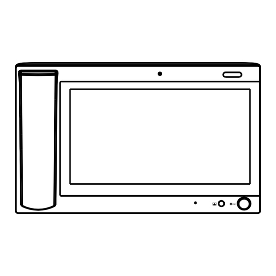
Page 5: Product Picture
Product Picture Camera Power LED Unlocking Product Features 1. Two-way communication with indoor monitor; 2. Monitor wall panel and unit panel; 3. Alarm and intercom information can be recorded; 4. Automatic message and answering can be set; Technical Parameters 1. Rated voltage: DC12V 2. -
Page 6: Operations
Operations Main interface Main menu: call, monitor, security, system settings, talk records and Apps. Status bar: network status, SIP registration. Status bar description: 1.Network status : When there is a network connection, the icon is always on; 2.SIP registration : When the SIP registration is successful, the icon is always After entering the secondary menu, the status bar will be displayed at the bottom of the screen. -
Page 7: Call
1.1 Call Clicking the icon , the system will enter into the following interface: Input building No. of 1-4 digits+ “Building” icon + unit No. of 1-2 digits + “Unit” icon+ room No. of 1-4 digits(floor No. included), then click icon to call. -
Page 8: Monitor
When the call is answered, call status is as below: ①If the called indoor monitor has a camera, the image of called party will be displayed in the management center. ②At the same time, the video of indoor monitor is transmitted to management center. -
Page 9: Security
1.2.1 Monitor Wall Panel Click the icon , enter two digits, and then click the icon monitor wall panel. 1.2.2 Monitor Unit Panel Click the icon , enter 7 digits, and then click the icon monitor unit panel. The first four digits are building No., the following two digits are unit number, and the last one is the number of outdoor panel. -
Page 10: Settings
This interface records the alarm information sent by indoor monitor to the management center machine. When indoor monitor gives an alarm, the interface will display the alarm address and alarm type, and the current record will be displayed in red. Click the alarm processing icon, the record will be displayed in black and saved in the alarm record list. - Page 11 If you want to enable the functions of camera, automatic message, automatic answering and alarm logger, check the boxes, swipe left and right to adjust the intercom volume, and then click "OK" icon. 1.4.2 Network Settings Clicking "Network", admin password window will pop up. Enter the admin password and click ok.
- Page 12 DHCP:When enabled, the router automatically allocates the IP address. IP address: In same network segment of the same system, IP address can not be repeated. Subnet mask: The original subnet mask is 255.255.255.0 and does not need to be changed.If the user needs to make changes, click the setting box next to the item, enter the content to be set through the numeric keypad that pops up, and then click "OK"...
- Page 13 Index: the number of management center, which can be up to 2 digits. Device code: when the device code is set to 0, the management center is the main management center; When the device code is 1 to 4, it is the sub management center.
-
Page 14: Talk Record
Click the input box after the old password, enter the original password through the numeric keypad that pops up, enter the new six-digit password in the same way and then re-enter the password in the box next to the item "Confirm". Clicking "OK", the system will emit a beep. 1.5 Talk records Clicking the icon on the main interface, the system will enter... -
Page 15: Application
1.6 Application Click icon on the main interface to enter into application function interface. Gadgets: Email, Calculator, Peoples(Contacts), Sound Recorder, Calendar, Camera, Music, etc. Data storage: Media Player, File Manager, Downloads. Extended application: you can download the software you need from the browser. -
Page 16: Web Setup
Web Setup Connect the management center and the computer by the switch, input the IP address of the management center on the computer web browser ( IP address of the computer and management center must be in the same network segment), then input the user name and password (the default user name of the system is "admin", and the password is "123456") to enter the interface: 2.1 Network Settings... -
Page 17: Room No. Settings
2.2 Room No. Settings Click the icon "Room No. ", and the system will enter the interface as shown below: The settings are the same as the ones of management center. After setup, click Submit to enable the settings. 2.3 VOIP Click the icon"VOIP"... -
Page 18: Advanced Settings
The settings are the same as the system settings of management center. To connect to SIP phone from other manufacturer, please check "SIP enable" and input the number registered in SIP server in box "User". Timeout: talking time of management center After setup, click Submit to enable the settings. - Page 19 Auto Pickup: checking the box, the management center will automatically answer the call, when outdoor panel calls but there is no answer within 10s. Deaf-mute mode: Check the box to enable this function, that is, when calling the management center, the light connected to the alarm interface of the management center will flicker directly.
-
Page 20: Webkit Settings
2.5 Webkit settings Click the icon "Webkit " , and the system will enter the interface as shown below: Advertising: link to the WEB page, make the WEB page into the form of picture playing, and play it when the management center is in standby mode. Browser: this item is invalid. -
Page 21: License Settings
Click "Reboot" to reboot the system. 2.7 License settings Click the "License" icon, and the system will enter the interface as shown below: Input the code in "LICENSE" and click "Submit" to enter the above interface. -17-... -
Page 22: Logout
2.8 Logout Click the icon "logout" , and the system will enter the interface as shown below: Click "Submit" to log out of the system. -18-... -
Page 23: System Configuration
System Configuration CAT-5e+RVV2 CAT-5e+RVV2 Terminal Terminal *1.0 CAT-5e Audio extension (optional) CAT-5e Audio extension (optional) *1.0 Power 220V Power 220V Audio extension (optional) Audio extension (optional) Network Switch Network Switch RVV2*0.5 RVV2*0.5 Terminal Terminal 220V 220V Power Power CAT-5e CAT-5e Audio extension (optional) Audio extension (optional) Terminal... -
Page 24: System Diagram
System Diagram 5.1 Power Interface Power Input Interface of Management Center: connect with 12V DC power supply. Power Interface 5.2 Network interface Connect to outdoor panel, indoor monitor or other network device through a switch. With POE function, POE switch can be connected to supply power to management center . -
Page 25: Installation
Installation Model:VG10-B21A Installation diagram Size and Appearance 1.Mainframe 2.Handset Step 1 3.Stand Product size: 303*195*35mm Step 2 Installation: desktop installation 4.Base -21-... -
Page 26: Troubleshooting
Troubleshooting Troubleshooting Some common failures and troubleshooting methods are listed for your reference. In case of failure that cannot be repaired, do not disassemble or repair the product by yourself. Please contact the after-sales service department. The machine cannot be turned on or automatically shut down. Check if the power supply is off and power it on again. -
Page 27: Safety Precaution
Safety Precaution In order to protect you and others from harm or your device from damage, please read the following information before using the device. Do not install the device in the following places: Do not install the device in high-temperature and moist environment or the area close to magnetic field, such as the electric generator, transformer ormagnet.
Need help?
Do you have a question about the VG10-B21A and is the answer not in the manual?
Questions and answers