Table of Contents
Advertisement
Quick Links
Installation, use and maintenance manual.
HYDRODENS
Gas-fired, condensing domestic hot
water generator.
HY49-350
Installation, use and maintenance manual
Read and follow the following instructions before installing the appliance.
Always keep this manual at hand during maintenance.
This manual is also available in electronic format and can be downloaded from the website
www.flexiheatuk.com
210-0069.02.docx
2024-04
Advertisement
Table of Contents

Related Manuals for Flexiheat HYDRODENS HY49-350


Summary of Contents for Flexiheat HYDRODENS HY49-350
- Page 1 Installation, use and maintenance manual. HYDRODENS Gas-fired, condensing domestic hot water generator. HY49-350 Installation, use and maintenance manual Read and follow the following instructions before installing the appliance. Always keep this manual at hand during maintenance. This manual is also available in electronic format and can be downloaded from the website www.flexiheatuk.com 210-0069.02.docx 2024-04...
-
Page 2: Table Of Contents
Installation, use and maintenance manual. SUMMARY GENERAL WARNINGS ................................. 3 TRANSPORT, STORAGE AND RECYCLING ............................ 4 CORRECT DISPOSAL OF THE PRODUCT............................4 CONTENTS, WEIGHT AND DIMENSIONS OF THE PACKAGING ....................5 EQUIPMENT CATEGORIES ................................5 TECHNICAL DATA ..................................6 DESTINATION COUNTRIES AND GAS CATEGORIES ........................7 DATA PLATE .................................... -
Page 3: General Warnings
Installation, use and maintenance manual. 1. GENERAL WARNINGS THIS INSTRUCTION MANUAL CONSTITUTES AN INTEGRAL AND ESSENTIAL PART OF THE APPLIANCE AND MUST BE CAREFULLY STORED NEAR THE APPLIANCE ITSELF FOR ANY FURTHER CONSULTATION. IT CONTAINS IMPORTANT INFORMATION REGARDING SAFETY, INSTALLATION, USE AND MAINTENANCE. -
Page 4: Transport, Storage And Recycling
Installation, use and maintenance manual. 2. TRANSPORT, STORAGE AND RECYCLING • The appliance must be transported and stored dry and protected from frost. • The appliance must be stored, transported and used at a temperature between +10 and +40 C° and at a humidity between 40% and 80%. -
Page 5: Contents, Weight And Dimensions Of The Packaging
Installation, use and maintenance manual. 4. CONTENTS, WEIGHT AND DIMENSIONS OF THE PACKAGING The appliance is delivered packaged in a wooden case with appropriate protections. A separate box contains the flue adapter. See table below for packaging dimensions. unit of HY49-350 measurement 1967... -
Page 6: Technical Data
Installation, use and maintenance manual. 6. TECHNICAL DATA unit of HY49-350 measurement Nominal heat input Q - nominal calorific flow rate QN 49.9 Minimum heat flow Q - minimum calorific flow rate Qm Nominal thermal power P - nominal thermal output PN 50.6 Minimum thermal power P - minimum thermal output Pm Gas consumption G20... -
Page 7: Destination Countries And Gas Categories
Installation, use and maintenance manual. 7. DESTINATION COUNTRIES AND GAS CATEGORIES Type of flue Supply pressure Category Reference gas Destination Country system [mbar] AT, BG, CH, CY, CZ, DK, EE, ES, FI, GB, GR, HR, IE, IT, LT, LU, LV, NO, PT, RO, SE, SI, SK, B23, B53 C13, C33, C43, C53, C63, C83 I2Esi... -
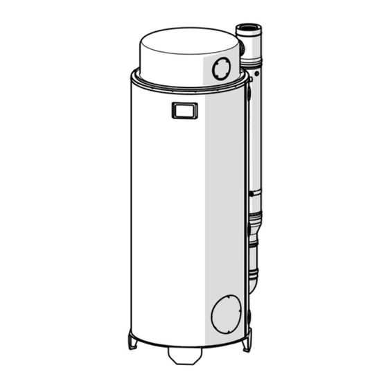
Page 8: Dimensions And Features Of The Appliance
Installation, use and maintenance manual. 9. DIMENSIONS AND FEATURES OF THE APPLIANCE HY49-350 A WIDTH B BOILER WATER INLET C BOILER WATER RECIRCULATION D BOILER WATER OUTLET 1605 E CONDENSATE DRAIN F FLUE ANALYSIS G ELECTRICAL POWER SUPPLY 1605 H GAS INLET / AIR INTAKE ANALYSIS 1659 I BOILER INSPECTION FLANGE L COMMAND DISPLAY... -
Page 9: Functional And Construction Description
Installation, use and maintenance manual. 10. FUNCTIONAL AND CONSTRUCTION DESCRIPTION The purpose of this appliance is to produce domestic hot water, thanks to the heat exchange between the flue gas and the water stored in the tank, through a heat exchanger which is in contact with the burner and the tank. Combustion occurs in a completely sealed manner with respect to the room where the appliance is installed, taking the air necessary for combustion and discharging the combustion products outside the room where the unit is installed. -
Page 10: Safety And Installation Local Regulations
Installation, use and maintenance manual. 11. SAFETY AND INSTALLATION LOCAL REGULATIONS LOCAL REGULATIONS During installation, local regulations relating to: Fire fighters Gas company Power supply company Hygiene and health office SAFETY RULES • Turn off the water heater and cut off the power supply to the unit, before carrying out any cleaning or maintenance intervention. -
Page 11: Installation
Installation, use and maintenance manual. 12. INSTALLATION IMPORTANT: THE INSTALLATION OF THE APPLIANCE MUST BE CARRIED OUT BY QUALIFIED TECHNICIANS ONLY IN ORDER TO AVOID DAMAGE OR INJURY. Before installing the appliance, check that the nominal power supply voltage is 220/240V - 50Hz. •... -
Page 12: Flue Gas Exhaust
Installation, use and maintenance manual. 14. FLUE GAS EXHAUST Respect the provisions established by municipal, provincial, or sectoral regulations. The flue gases of more than one appliance must not be conveyed into the same flue gas duct. The appliance is supplied as standard without flue system. Purchase the flue kit depending on the type of exhaust you want to carry out. - Page 13 Installation, use and maintenance manual. FLUE SYSTEM ADAPTER The flue system connector, supplied as standard and ready to be installed, has a diameter of Ø100/150 and is made of PP/Stainless steel material. It is equipped with an air and smoke exhaust inspection at the two ends of the duct. IMPORTANT: LEAVE A CLEARANCE OF MINIMUM 60 CM ABOVE THE APPLIANCE TO ALLOW ANY MAINTENANCE INTERVENTION ON THE TOP PART 210-0069.02.docx...
-
Page 14: Water Connections
Installation, use and maintenance manual. 15. WATER CONNECTIONS Comply with the following domestic water parameters: Total hardness: between 10 and 25 °f PH: between 6 and 8 Chlorides: maximum value 200 mg/l Conductivity: maximum value 2500 μS/cm HYDRAULIC COMPONENTS TO INSTALL (NOT INCLUDED) T-shaped drain valve. -
Page 15: Electrical Connections
Installation, use and maintenance manual. GAS CONNECTION Connect the gas supply line to the threaded fitting on the appliance using a removable rigid fitting. The gas connection is G 3/4": fit a manual gas shut-off valve along the pipe near the generator and in an easily accessible position. -
Page 16: Command Description
Installation, use and maintenance manual. 17. COMMAND DESCRIPTION 18. THERMOSTAT ADJUSTMENT START When you turn the display on for the first time, you will be asked to set the language, in which the device is used, the day and time: The display has interactive touch controls. -
Page 17: Operating Cycle
Installation, use and maintenance manual. If the water temperature is lower than the one set on the 19. OPERATING CYCLE display, the burner ignition sequence will start: During the ignition phase, the system always behaves as described below: The fan is activated and reaches the on speed. The system starts counting the pre-ventilation time. -
Page 18: Co2 Regulation
Installation, use and maintenance manual. 20. CO2 REGULATION At the end of the installation, it is necessary to check the CO2 values: in the event of a defect, it is necessary to make an adjustment to restore the values as indicated in the table. In the event of a gas change and/or air intake or exhaust duct change, the CO2 values will have to be readjusted according to the new type of flue system. - Page 19 Installation, use and maintenance manual. READING AND ADJUSTMENT OF CO2 VALUES AT MINIMUM POWER ▪ With the boiler already in “chimney sweep” mode, press the [-] key to activate the LOW chimney sweep. ▪ Detect the CO2 value on the analyzer, through the same inspection on the bend.
-
Page 20: Gas Change
Installation, use and maintenance manual. 21. GAS CHANGE To change the gas, replace the mixer with the specific model for the gas of destination. Proceed by removing the upper cap to access the mixer. REMOVE THE TOP COVER Remove the screws around the shell using a screwdriver (not supplied). Remove the screws on the rear flange of the tee fitting with a hex wrench (not supplied). - Page 21 Installation, use and maintenance manual. MIXER REPLACEMENT Loosen the metal band and remove the tube outwards. Remove the 3 screws on the mixer and unscrew the nut on the gas fitting. Replace the mixer with the reference model. Reassemble the removed components ATTENTION: IN CASE OF WORN SCREWS AND/OR SEALS FOLLOWING THE REPLACEMENT OF THE MIXER, PROCEED WITH THEIR REPLACEMENT 210-0069.02.docx...
-
Page 22: Timer Programming
Installation, use and maintenance manual. 22. TIMER PROGRAMMING In the first step, enter the starting time using the [+] and [-] keys, at minimum intervals of 15 minutes, and confirm with The “Programming” menu allows to manage a weekly [OK]. If, however, you want to abandon the programming schedule. - Page 23 Installation, use and maintenance manual. The second item of the "Programming" menu allows to INTERNAL POWER RESERVE copy the program of one day to another, selecting the The display is equipped with an internal power reserve source day at the top and the destination day at the capable of buffering the absence of power for a few hours, bottom.
-
Page 24: Anti-Legionella Function
Installation, use and maintenance manual. 23. ANTI-LEGIONELLA FUNCTION WARNING: LEGIONELLA IS A BACTERIA THAT AFFECTS THE RESPIRATORY SYSTEM. THE PREVENTION OF THIS INFECTION IS BASED ON THE CORRECT DESIGN AND CONSTRUCTION OF WATER-SANITARY SYSTEMS. The appliance has an anti-legionella function, which allows to heat the water in the tank to prevent the bacterium from proliferating inside it. -
Page 25: Electronic Board And Wiring
Installation, use and maintenance manual. 26. ELECTRONIC BOARD AND WIRING MI860 MOTHERBOARD F - FUSE J1 – PWM Fan 3.15 A @ 250 VAC fast Pin: 1. 24 VDC J7 - L/N: Power supply 2. Speed signal input (Hall sensor) 3. - Page 26 Installation, use and maintenance manual. Pin: 3. GND J60 - Gas valve 4. Signal input Description: Modulating gas valve with pneumatic air-gas ratio control Voltage: Low (5 VDC) Pin: 1. Neutral J44 - Touch display 2. Line Description: Command board for viewing and setting information Voltage: High (230 VAC) Voltage: Low (5 VDC)
-
Page 27: Control Unit Faults
Installation, use and maintenance manual. 27. CONTROL UNIT FAULTS Any faulty operation is detected and displayed on the control board display. In particular, the item “Err.” appears at the bottom right, alternating with the specific error code for the anomaly in progress (or, if the system is affected by multiple anomalies at the same time, for the last anomaly detected). -
Page 28: Cathodic Protective System Faults
Installation, use and maintenance manual. 28. CATHODIC PROTECTIVE SYSTEM FAULTS The cathodic protection control unit has a LED to transmit information on the operating status, as well as alarm signals. The transmission of impulses occurs through a green or red sequence, with different intermittences. Below is the diagram with the meaning of the various signals: WHEN SWITCHING ON: BEGINNING OF USE TIME COUNTING 3 rapid red flashes = start of the counting function... -
Page 29: Periodic Maintenance
Installation, use and maintenance manual. 29. PERIODIC MAINTENANCE To ensure the safety of the appliance and prolong its life, it is necessary to have it checked at least once a year by an authorized service centre, who will carry out the following operations: •... -
Page 30: Maintenance Sheet
Installation, use and maintenance manual. 31. MAINTENANCE SHEET SERIAL SERIAL DATES DESCRIPTION SIGNATURE 210-0069.02.docx 2024-04... - Page 31 Installation, use and maintenance manual. 210-0069.02.docx 2024-04...
- Page 32 hot water generator model. HY49-350 complies with European Directives: 2016/426/EU – Gas Appliances Regulation (GAR) 2014/35/EU – Low Voltage Directive (LVD) 2014/30/EU – Electromagnetic Compatibility Directive (EMC) 2013/814/EU – Ecocompatibility Regulation (ErP) 210-0069.02.docx 2024-04...
Need help?
Do you have a question about the HYDRODENS HY49-350 and is the answer not in the manual?
Questions and answers