
Related Manuals for EOS Mill Wheel


Summary of Contents for EOS Mill Wheel
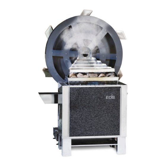
- Page 1 EOS Mill Wheel for Mill-Sauna Installation and operating instruction Made in Germany IPx4 Druck Nr. 29022878 en / 22.24 Technical changes reserved...
-
Page 3: Table Of Contents
English Table of Contents Scope of delivery ............................4 Important Notes ............................5 Installation ..............................6 Align mill ..............................6 Install Cascade ............................7 Install Water Tank ..........................7 Set up Fixed Water Connections ......................8 Set up Connection Fixed Water Connection - Water Tank ............8 Connect Fixed Water Connection with Water System On-Site..........9 Construction overview ........................ -
Page 4: Scope Of Delivery
The mill wheel and the sauna heating device together make up our mill-sauna. The sauna heater is not included in the scope of delivery and must be ordered separately. -
Page 5: Important Notes
Pay attention to all measurement specifi cations and the following notes. • The mill wheel must only be used in connection with the sauna heating device EOS 34GM, EOS Goliath and the associated sauna control unit.. • The device has been designed for a connection voltage of 230 V ~ . -
Page 6: Installation
Installation Installation NOTICE Notice Prior to the installation of all individual components all protective foils must entirely be removed.. Align mill ► Put the stator with the column onto the desired place and align horizontally by means of the plate feet. -
Page 7: Install Cascade
We recommend to use a water level. Fig. 6 Install Water Tank ► Insert water tank sideways. NOTICE Consider position of shovel. Fig. 7 NOTICE Non-contact run between cascade inflow channel and mill wheel must be guaranteed (approx. 5 mm tolerance). approx. 5 mm Fig. 8... -
Page 8: Set Up Fixed Water Connections
Installation By height adjustment of the cascade you can control the water quantity which fl ows across Cascade the cascade. holder • high lying cascade: low water quantity • low lying cascade: high water quantity The height can be adjusted by means of the long holes. -
Page 9: Connect Fixed Water Connection With Water System On-Site
Installation Connect Fixed Water Connection with Water System On-Site ► NOTICE Important notes Between fi xed water system and fi xed water connection a shut-off cock must be installed In case th fixed water connection will not be used for any length of time, the shut-off cock is to be closed. -
Page 10: Construction Overview
Installation Construction overview ► The float (G) opens or closes the valve (C),to ensure that the tank remains full. The water level can be regulated by turning the float. Fig. 13 Fig. 12 A. Reducing coupling ¾“ to ½“ B. Seal ¾“ C. -
Page 11: Installation And Connection Of Control Unit
To this end, open the housing and fi t to the intended place with four screws. Lay the fed line to the mill wheel and connect it to the motor connection on the rear of the mill wheel. With the 4-wire line, we provide you with the usage of two potential-free contacts (Signal 1 and signal 2). -
Page 12: Installation
Installation Installation Installation Connections control unit A. DIP-switch B. Terminals for light and fan C. Terminasl for mains 230V D. Main switch ON/OFF E. Cable glans (drive / mains / light and fan) F. Terminals for the external push-button... -
Page 13: Wiring Diagram
Installation Installation Wiring diagram MAIN SUPPLY / NETZVERSORGUNG CONNECTOR 230V ~ TO MOTOR STECKER ZUM MOTOR 1 2 3 4 SWITCH / SCHALTER Motor Motor blue violet brown 3,3V Wiring diagram im Eigendruck 106 x 130 Schaltplanaufkleber für Mühlensteuerung... -
Page 14: Mounting Of Optional Accessories
Installation Mounting of optional accessories General security provisions • The electrical installation must be performed by authorised electricians only. • The provisions of your public utility and the relevant VDE provisions (DIN VDE 0100) must be observed. • Beware, danger of life: Never perform repairs and installations yourself. The housing must only be removed by an expert. -
Page 15: Commissioning
Installation Commissioning Commissioning The settings for water splash events are made with the DIP-Switch on the main board. ATTENTION: Make settings (DIP-Switch) only with the system disconnected from power! DIP-Switch ► 2 3 4 5 A. Position ON B. Position OFF ... - Page 16 Commissioning Installation Switching to an external push-button ► Using the DIP-switch no. 5 you can set the operation control to be made from an external push-button. Switch 5 „ON“ - control from an external push-button. Settings made with switches ƒ 3 and 4 remain inactive.
-
Page 17: Mounting Instructions For The Remote Control Button (Optiona Item No. 94.4087)
Installation Mounting instructions for the remote control button (optional Item no, Art.-Nr. 94 4087) WARNING The button must only be installed outside of the cabin. When using the button inside the cabin, there is a danger of burning! WARNING Children should be supervised to ensure •... -
Page 18: Electric Connection Of The Button
Installation Electric connection of the button WARNING Risk of electric shock A faulty electrical connection poses the risk of an electric shock. This risk remains also after completion of the installation work. • Disconnect the system entirely from the mains supply. •... -
Page 19: Maintenance
Only switch the mill on when the heater and sauna stones are at operating temperature. This takes approx. 45 minutes. Switch the mill wheel on using the ON/OFF switch. The programme prodedure starts. To use an optional remote start button, DIP switch 5 must be set to ON. -
Page 20: Dimensions
Installation Dimensions ► ~ 1180 1250 alle Maße in mm... -
Page 21: Installation Сascade And Water Gutter For Goliath
Installation Installation Cascade and water for heater EOS Goliath 94 6222... -
Page 22: Recycling
Electronic waste Electronic waste must be disposed of at the designated local collection point for electronic waste. Additional disposal note for commercial users: Further disposal instructions can be found under the link www.eos.sauna.de/recycling Service Address EOS Saunatechnik GmbH Tel: +49 (0)2775 82-514... -
Page 23: General Terms And Conditions Of Service
The manufacturers General Terms and Conditions of Business, The manufacturer shall assume liability in accordance with the which can be found at www.eos-sauna.com/agb, shall apply in currently applicable statutory regulations. The packaging for all addition to the foregoing terms and conditions of service.
Need help?
Do you have a question about the Mill Wheel and is the answer not in the manual?
Questions and answers