Table of Contents
Advertisement
Quick Links
v
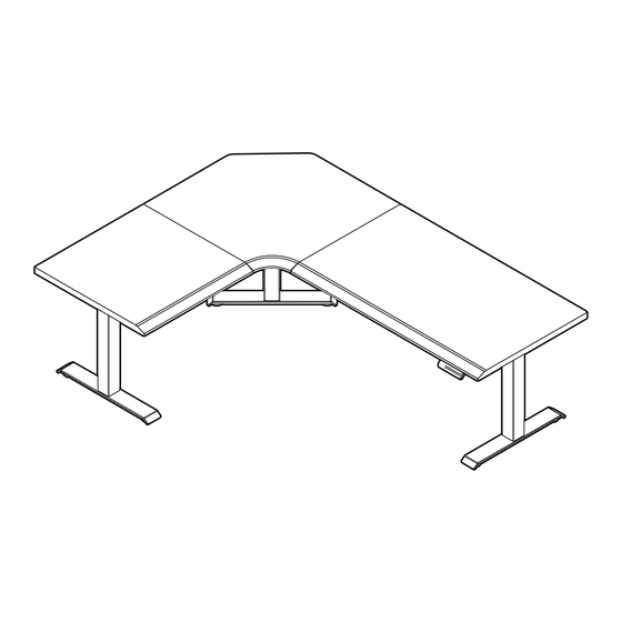
L-Shape Electric Standing Desk
Bureau debout électrique end forme de L
Patent and trademark information: vari.com/patents | V1.3, ©2024 Varidesk, LLC All rights reserved.
Informations sur les brevets et les marques : vari.com/patents | V1.3, ©2024 Varidesk, LLC Tous droits réservés.
L
L
Holds up to 200 lb (90.72 kg)
Peut soutenir jusqu'à 200 lb (90,72 kg)
2 People Required for Assembly
2 Personnes Requis pour l'assemblage
R
Advertisement
Table of Contents

Related Manuals for Vari L-Shape Electric Standing Desk


Summary of Contents for Vari L-Shape Electric Standing Desk
- Page 1 Peut soutenir jusqu’à 200 lb (90,72 kg) 2 Personnes Requis pour l’assemblage Patent and trademark information: vari.com/patents | V1.3, ©2024 Varidesk, LLC All rights reserved. Informations sur les brevets et les marques : vari.com/patents | V1.3, ©2024 Varidesk, LLC Tous droits réservés.
-
Page 2: Included Parts
Included Parts Pièces incluses *Desktops and leg kit ship in separate boxes and could arrive in separate deliveries. Le bureau et les pieds sont expédiés dans des boîtes séparées et pourraient arriver dans des livraisons séparées. Box 1 of 3 Boîte 1 de 3 SUPPORT PLATE SIDE FRAME... -
Page 3: Desk Assembly
Tools Needed Desk Assembly (Not Included) Outils nécessaires (non inclus) Assemblage du bureau • PHILLIPS SCREWDRIVER Tournevis cruciforme LEFT Gauche RIGHT Droite Determine your desired desk orientation (short desktop on the right or left side). Refer the L and R stickers underneath the desktops to help determine your desired orientation. - Page 4 PINS Pions SIDE FRAME CADRE LATÉRAL CORNER FRAME CADRE D'ANGLE (8) M8 SCREW SETS (8) ENSEMBLES M8 NOTE: We recommend assembling the desk face down on a smooth, debris-free, flat surface to prevent scratches. The short desktop on the right is an assembly example. Align the LONG and CORNER DESKTOPS together. Then align the pins in each frame with the pre-drilled holes for the long and corner desktops.
- Page 5 SUPPORT RAIL B RAIL DE SUPPORT B SUPPORT RAIL A SUPPORT RAIL D RAIL DE SUPPORT A RAIL DE SUPPORT D SUPPORT RAIL C RAIL DE SUPPORT C (6) M8 SCREW SETS (6) ENSEMBLES M8 Place SUPPORT RAILS A, B, C, and D into the grooved areas on each side of the frame. Then, slide the support rails into place and insert (6) M8 SCREW SETS into the support rails.
- Page 6 (3) LEGS (3) JAMBES (6) M6 X 14 SCREWS (6) VIS M6 X 14 (6) M6 WASHERS (6) RONDELLE M6 Place the LEGS into the grooved areas inside each metal frame, including the third unatt ached frame. Aft er each leg is placed in the frame, confi rm proper alignment by pushing the leg towards the outside of the frame. Then use the 4MM ALLEN KEY provided to securely ti ghten (2) M6 SCREWS and (2) M6 WASHERS into each leg.
-
Page 7: Control Box Bracket
If you received (2) ST5 X 16 TAPPING SCREWS to install the CONTROL BOX, proceed with the step below. Si vous avez reçu (2) VIS AUTOPERCEUSES ST5 X 16 pour installer le BOÎTIER DE COMMANDE, passez à l'étape ci-dessous. (2) ST5 X 16 TAPPING SCREWS (2) VIS AUTOPERCEUSES ST5 X 16 CONTROL BOX BOÎTIER DE COMMANDE... - Page 8 (2) ST4 X 19 TAPPING SCREWS (2) VIS AUTOTARAUDEUSE ST4 X 19 CONTROL PANEL BRACKET SUPPORT DE PANNEAU DE CONTRÔLE Align the CONTROL PANEL BRACKET over the pre-drilled holes on the LONG DESKTOP and use (2) ST4 X 19 TAPPING SCREWS and a Phillips head screwdriver (not included) to att ach the bracket. (It is recommended to install the Control Panel on the outside edge of the long desktop.) Alignez SUPPORT DE PANNEAU DE CONTRÔLE sur les trous pré-percés du plateau long et uti lisez (2) VIS AUTOTARAUDEUSES ST4 X 19 et un vtournevis cruciforme (non inclus) pour fi xer le support.
- Page 9 Two people should carefully fl ip the assembled desk and unatt ached leg to an upright positi on. NOTE: The short side rails need to be fully mounted to the center desktop, and it is not recommended that you hold them to fl ip the table or the plates &...
-
Page 10: Control Panel
CONTROL PANEL BRACKET SUPPORT DE PANNEAU DE CONTRÔLE ADHESIVE CLIPS CLIP ADHÉSIF CONTROL PANEL PANNEAU DE CONTRÔLE CONTROL BOX BOÎTIER DE COMMANDE Locate the CONTROL PANEL and slide it into the BRACKET to att ach to the desk. Once the panel is in place, connect its cable to the corresponding CONTROL BOX input labeled HS. - Page 11 Figure B Figure A AC = Power Cord M1 = Center Leg Cable M2 = Side Leg Cable M3 = Side Leg Cable HS = Control Panel AC = Cordon d'alimentati on M1 = Câble de la jambe centrale M2 = Câble de la jambe latérale M3 = Câble de la jambe latérale HS = Panneau de contrôle Connect the cable of the corner leg to the SHORT EXTENSION CABLE (Figure A).
-
Page 12: Initial Setup
Product Setup & Adjustments Initial Setup Press the DOWN butt on on the control panel unti l the base reaches its lowest positi on. Press and hold the DOWN butt on again unti l the LED display reads “RST”. Press and hold the 1 butt on (about 5 seconds) while the LED fl ashes “RST” and switches to either: 10.1 = One-Touch (preset butt ons work with one quick press) 10.2 = Constant-Touch (preset butt ons work when pressed and held down for a few seconds) Release the 1 butt on. -
Page 13: Configuration Initiale
Confi guration et réglages du produit Confi guration initiale Appuyez sur le bouton DOWN (bas) du panneau de commande jusqu’à ce que la base att eigne sa positi on la plus basse. Appuyez sur le bouton DOWN (bas) et maintenez-le enfoncé jusqu’à ce que l’affi chage DEL indique « RST ». Appuyez sur le bouton 1 et maintenez-le enfoncé... - Page 14 50 ½" (128 cm) Highest Setting Preferred Lowest Setting 25" (63.5 cm) Lowest Setting Height Settings and Preferences The height setti ngs range from 25-50.5 inches (63.5-128 cm). You can program 4 height prefer-ences by raising or lowering the desk to your desired height, pressing the “M” butt on (you will see “S-” appear on the display), then pressing 1, 2, 3, or 4. Setting Upper &...
- Page 15 128 cm (50,5 po) Réglage le plus élevé Réglage préféré le plus bas 63,5 cm (25 po) Réglage le plus bas Paramètres de hauteur et préférences Les réglages de hauteur vont de 63,5 à 128 cm (25,0 à 50,5 po). Vous pouvez programmer 4 hauteurs de préférence en élevant ou abaissant le bureau à...
-
Page 16: Control Panel Lock
If the legs have no response, your desk may need to be reset. Follow the initi al setup instructi ons and ensure all connecti ons are in the correct locati on and fully plugged in. If the legs are rising slowly, check the input power connecti on to make sure it’s secured correctly. If any errors conti nue, please contact Vari. -
Page 17: Verrouillage Du Panneau De Commande
Si les pieds ne répondent pas, il se peut que votre bureau doive être réiniti alisé. Suivez les instructi ons de confi gurati on initi ale en vous assurant que tous les branchements sont au bon endroit et correctement enfoncés. Si les pieds se montent lentement, vérifi ez la connexion d’alimentati on d’entrée afi n d’assurer qu’elle est correctement fi xée. Si les erreurs persistent, veuillez communiquer avec Vari. - Page 18 Changing Anti-Collision Sensitivity If the desk is bumped or shaken too hard, it can trigger the anti-collision reaction. Follow the below steps to control how much interference/motion is required to trigger the desk anti-collision. 1. Put the control panel into “RST” mode (refer to the System Reset steps on the opposite page). 2.
-
Page 19: Troubleshooting Solution
Suivez les instructions ci-dessous pour réinitialiser (RST) le bureau. Si le code d'erreur persiste, vérifiez les connex- ions. Vérifiez qu’aucun câble n’est pincé ou endommagé. Si l'erreur persiste, contactez Vari. If the desk is raised and lowered continuously for more than 2 minutes or the room tempera- ture is too high, it will display this code and cease working temporarily to protect the mecha- nism from overheating. - Page 20 WARNING: Do not open any components; there is a danger of AVERTISSEMENT : N’ouvrez aucun des composants, il existe un risque electric shock. d’électrocution. WARNING: Risk of electric shock. Connect this desk to a AVERTISSEMENT : Risque de décharge électrique. Ce bureau doit properly grounded outlet only.
Need help?
Do you have a question about the L-Shape Electric Standing Desk and is the answer not in the manual?
Questions and answers