Advertisement
Quick Links
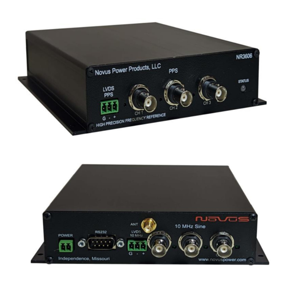
10MHz Frequency Reference, 6 Channel
OCXO, GNSS Locked, 3 Channel Sine, 3-
Channel PPS, Plus a PPS-LVDS Channel
All information provided herein is the property of Novus Power Products LLC. The information
included may be reproduced without the permission of Novus Power Products LLC. for the
purpose of operating the equipment.
Page 1 of 27
NR3606
and a 10 MHz LVDS
USERS MANUAL
REVISION
DATE
www.novuspower.com
NR3606
B
062024
Advertisement

Related Manuals for Novus NR3606


Summary of Contents for Novus NR3606
- Page 1 Channel PPS, Plus a PPS-LVDS Channel and a 10 MHz LVDS All information provided herein is the property of Novus Power Products LLC. The information included may be reproduced without the permission of Novus Power Products LLC. for the purpose of operating the equipment.
- Page 2 NR3606 REVISION DATE 062024 Table of Contents Safety ................................4 Summary ............................... 5 OCXO based NR3606-O ..........................6 GNSS locking-NR3606-OG ......................... 6 Power- ............................... 7 Outputs: ..............................8 RS232 ................................ 9 Controls and Indicators ..........................10 Front Panel .............................. 10 LEDs .................................
- Page 3 USERS MANUAL NR3606 REVISION DATE 062024 LIMITED HARDWARE WARRANTY ....................... 26 Page 3 of 27 www.novuspower.com...
- Page 4 USERS MANUAL NR3606 REVISION DATE 062024 Safety This product has been designed and manufactured to recognized safety standards and rules. This product is a sophisticated electronic instrument that should be installed and operated by highly trained professionals. Installation of this equipment should comply with all local electrical codes.
- Page 5 USERS MANUAL NR3606 REVISION DATE 062024 Summary Page 5 of 27 www.novuspower.com...
- Page 6 NR3606 REVISION DATE 062024 The NR3606 is a versatile OCXO based reference platform that can be configured to meet a wide range of applications: OCXO based NR3606-O reference that is stable to 5ppb/day. The OCXO selected is a low phase noise reference. The unit will synthesize a PPS signal from the 10 MHz OCXO.
- Page 7 REVISION DATE 062024 Power- the NR3606 can be powered from an external DC power source that ranges from -60 to +60 Vdc < 5 watts This is accomplished in three ranges: 12VDC (10 to 15VDC) 24VDC (20 to 30VDC) 48VDC (40 to 60VDC)
- Page 8 DATE 062024 Outputs: The NR3606 has a total of: 3- 10 MHz outputs. These can be 1 Vrms sine outputs or three 10 MHz square outputs at 5 volt CMOS levels. Either configuration can drive a 50 Ohm load. 3-PPS outputs- these can be set at the factory to drive either 3.3 or 5 volt CMOS levels into 50 Ohms.
- Page 9 USERS MANUAL NR3606 REVISION DATE 062024 RS232 this serial port provides NMEA data and unit status. The NR3626- O/G can accept user commands which will provide specific status and performance feedback, and which may be customized by the user. Many of the settings can be saved in non-volatile flash memory.
- Page 10 This section describes the functionality of the front panel controls and indicators. LEDs Four front panel LEDs provide a quick indication of the NR3606 status. The STATUS indicator will illuminate solid green if both GNSS receivers have acquired GPS lock and are actively controlling the respective modules.
- Page 11 USERS MANUAL NR3606 REVISION DATE 062024 Input/Output Connectors/Mechanical All versions of the NR3606 1.512 5.997 5.658 3.954 2.846 2.754 1.968 1.775 1.149 .933 5.948 6.998 GPS Ant - SMA connects to the GPS ant - provides 3.3 VDC 25mA max.
- Page 12 USERS MANUAL NR3606 REVISION DATE 062024 RS232 DB9 An RS232 port is provided for local setup, and status monitoring. The embedded processor provides status strings, as well as command responses. Configuration and status commands are detailed in the Programmer’s Manual Section 5.0.
- Page 13 The unit is designed to operate from 12 VDC (default) nominal power and is reverse polarity protected. Power- the NR3606 can be powered from an external DC power source that ranges from -60 to +60 Vdc < 5 watts This is accomplished in three ranges:...
- Page 14 USERS MANUAL NR3606 REVISION DATE 062024 The unit is also reverse polarity protected by using an internal diode bridge. The internal DC to DC converter completely isolates the power ground from the signal ground to minimize power noise from interfering with the output signals.
- Page 15 Antenna - SMA SMA female antenna connection. Provides internal 3.5VDC power at <25mA max. The Novus NA103 pole mount antennas or the Novus NA106 magnetic mount antenna are recommended for optimal performance. The receiver and companion elements generate the PPS and NMEA serial link.
- Page 16 USERS MANUAL NR3606 REVISION DATE 062024 DC Input 2.8V - 6V Noise Figure <2.0dB Power Consumption 25mA (typ) PPS (Pulse Per Second) The PPS (one Pulse Per Second) relationship with the NMEA data is shown below: The serial data timing is for the next rising edge of the PPS pulse.
- Page 17 USERS MANUAL NR3606 REVISION DATE 062024 GNSS PPS Accuracy 15ns(1σ) (@-130 dBm) 50ns(1σ) (@-150 dBm) The nominal accuracy of a PPS signal that is directly from the radio is on the order of 25 ns rms. The signal will also have ~5 ns of jitter. The jitter is due to the characteristics of the transmission channel - multi-path and other radio effects.
- Page 18 10 MHz. The 5ns edge requires almost an order of magnitude more bandwidth than a 10 MHz signal even though most consider the PPS to be a 1 Hz signal. To address this problem, Novus offers PPS products with a configurable output drive section. Please discuss your drive requirements with a Novus Application Engineer.
- Page 19 USERS MANUAL NR3606 REVISION DATE 062024 PPS Connectors The PPS signal is available on the three BNC connectors and the three pin LVDS connector. The LVDS connector is labeled +-gnd this is meant to support a three wire twisted pair. The LVDS requires a 100 Ohm load at the client.
- Page 20 USERS MANUAL NR3606 REVISION DATE 062024 Phase Noise Low phase noise contribution is achieved through careful PCB design, component selection and minimization of power supply noise. Below is a typical phase noise performance for a 10 MHz reference application: Page 20 of 27...
- Page 21 062024 Crystal Novus crystal-based frequency reference products are based upon either TCXO or OCXO technology. Temperature compensated crystal oscillators will normally use an AT cut crystal and electronically compensate the device with temperature. An OCXO device uses a SC (stress compensated) crystal and the part is held at a fixed temperature to minimize temperature drift.
- Page 22 USERS MANUAL NR3606 REVISION DATE 062024 Over a broad temperature range, an AT performs very well and much easier to compensate electronically. It is also a simpler crystal to manufacture than a SC cut device. For applications where a stability of a few ppm is acceptable, a TCXO can be a cost-effective alternative.
- Page 23 Calibration feature tunes the OCXO and stores the calibration coefficients in non-volatile memory. For the NR3606-O product calibration may be required depending upon the application. The OCXO will drift with time and temperature. Drift of ±5ppb/day, ±50ppb/year is typical.Temp stability ±200ppb over the full temp range. OCXO’s with better temp and time stability and if required, contact the factory.
- Page 24 USERS MANUAL NR3606 REVISION DATE 062024 Technical Specifications 3-Output 10 MHz BNC 10 MHz,1.0 Vrms ±0.2, into 50 Ohms, Sine or 5 Volt CMOS levels Default is sine output 1-LVDS LVDS 10 MHz LVDS connector Digikey part number 277-1965-ND Typical Standard Phase Noise...
- Page 25 Tracking: -157 dBm Hot Start: -157 dBm Warm Start: -143 dBm Cold Start: -143 dBm Reacquisition: -157 dBm With Novus recommended antenna Antenna with LNA Antenna power 3.5 Vdc, < 35 mA (on center conductor) (factory configurable to 5 Vdc) Frequency...
- Page 26 Should Novus be unable to repair or replace the product within a reasonable amount of time, the customer’s alternate remedy shall be a refund of the purchase price upon return of the product to Novus. The liability of NOVUS under this warranty is limited to replacing, repairing or issuing a credit, at its option, for any such item returned by Buyer under the terms of this warranty.
- Page 27 INFORMATION (OR OTHER PECUNIARY LOSS) ARISING OUT OF THE USE OF OR INABILITY TO USE THE HARDWARE SUPPLIED THEREWITH EVEN IF NOVUS OR ANYONE ELSE HAS BEEN ADVISED OF THE POSSIBILITY OF SUCH DAMAGES, OR FOR ANY CLAIM BY ANY OTHER PARTY. EXCLUDED DAMAGES SHALL INCLUDE, BUT ARE NOT LIMITED TO: COSTS OF REMOVAL AND INSTALLATION, LOSSES SUSTAINED AS THE RESULT OF INJURY TO ANY PERSON, OR DAMAGE TO PROPERTY.
- Page 28 GPS/GNSS Receiver Communications Specification NMEA-0183 All information provided herein is the proprietary property of Novus Power Products L.L.C. The information included may be reproduced without the permission of Novus Power Products L.L.C. without prior approval for purpose of operating the equipment.
- Page 29 Users manual Appendix A Revision #: Date: 07-14-15 Table of Contents: COMMUNICATION SPECIFICATION ......................... 4 SERIAL DATA OUTPUT TIMING △4........................... 5 NMEA SENTENCE FORMAT ............................. 6 PROPRIETARY SENTENCE FORMAT: ........................7 STANDARD NMEA OUTPUT SENTENCES ........................8 GGA – G : ......................
- Page 30 Users manual Appendix A Revision #: Date: 07-14-15 PROPRIETARY NMEA OUTPUT SENTENCES ......................40 ACK – O : ......................40 UTPUT THE OMMAND ECEPTION HECK ORMAT CR – ERIDE GNSS CORE LIBRARY INTERFACE ...................... 41 ) △4△5 F CRW(TPS1) – O : ..........
- Page 31 Users manual Appendix A Revision #: Date: 07-14-15 Communication Specification Signal Lines used: TXD, RXD Flow Control: None System: Full Duplex Asynchronous Speed: Configurable, Default 38400 bps (*1) Start Bit: 1 bit Data Length: 8 bits Stop Bit: 1 bit Parity Bit: None Data Output Interval:...
- Page 32 Users manual Appendix A Revision #: Date: 07-14-15 Serial data output timing △ The output timing of serial data is synchronous with PPS output timing. Serial data is begun to output in the 25ms to 75ms range after PPS is output. The time of serial data indicates next PPS output timing.
- Page 33 Users manual Appendix A Revision #: Date: 07-14-15 NMEA Sentence Format 13.1 Standard Sentence Format: <address field> <data field> … *<checksum field> <CR> <LF> 5 bytes Field Description Start-of Sentence marker <address field> 5-byte fixed length. First 2 bytes represent a talker ID, and the remaining 3 bytes do a sentence formatter.
- Page 34 Users manual Appendix A Revision #: Date: 07-14-15 Proprietary Sentence Format: $ P <maker ID> <sentence type> , <data field> … *<checksum field> <CR> <LF> 3 bytes 3 bytes Field Description Start-of-Sentence marker Proprietary sentence identifier 3-byte fixed length. <maker ID> GT-87’s maker ID is “ERD”...
- Page 35 Users manual Appendix A Revision #: Date: 07-14-15 Standard NMEA Output Sentences The receiver supports eight standard NMEA output sentences (GGA, GLL, GNS, GSA, GSV, RMC, VTG and ZDA) per NMEA standard 0183 Version 4.10 (June, 2012). By default, the RMC, GNS, GSA, ZDA, GSV and TPS sentences will be output every second. The sentences can be independently enabled and disabled using the $PERDCFG,NMEAOUT and/or $PERDAPI,CROUT command described later in this document, as well as use differing transmission rates.
- Page 36 Users manual Appendix A Revision #: Date: 07-14-15 – Global Positioning System Fix Data Format: $XXGGA , hhmmss.sss , ddmm.mmmm , , dddmm.mmmm , <CR> <LF> Description Range “hh”: hour 00 - 23 “mm”: minute 00 - 59 “ss.sss”: second 00.000 - 59.999 2-3.
- Page 37 Users manual Appendix A Revision #: Date: 07-14-15 – △ Geographic Position - Latitude/Longitude Format: $XXGLL , ddmm.mmmm , a , dddmm.mmmm , , hhmmss.sss , a , a *hh <CR> <LF> Description Range 1-2. Latitude “dd”: degree 00 - 90 “mm.mmmm”: minute 00.0000 - 59.9999 “a”: North/South...
- Page 38 Users manual Appendix A Revision #: Date: 07-14-15 – GNSS Fix Data Format: $XXGNS , hhmmss.sss , ddmm.mmmm , , dddmm.mmmm , , c--c , <CR> <LF> Description Range “hh”: hour 00 - 23 “mm”: minute 00 - 59 “ss.sss”: second 00.000 - 59.999 Latitude 2-3.
- Page 39 Users manual Appendix A Revision #: Date: 07-14-15 △ – GNSS DOP and Active Satellites Format: $XXGSA , a , a , xx , xx , xx , … , xx , x.x , x.x , x.x , h *hh <CR> <LF> 6-13 Description Range...
- Page 40 Users manual Appendix A Revision #: Date: 07-14-15 △ – GNSS Satellites in View Format: $XXGSV <CR> <LF> Description Range Total number of messages 1 - 4 Number of messages 1 - 4 Number of satellites in line-of-sight 00 - 14 Sat.
- Page 41 Users manual Appendix A Revision #: Date: 07-14-15 Satellite number from 93 to 99 indicates QZSS (193 to 199) Page 14 of 58...
- Page 42 Users manual Appendix A Revision #: Date: 07-14-15 △ – Recommended Minimum Navigation Information Format: $XXRMC , hhmmss.sss , a , ddmm.mmmm , a , dddmm.mmmm , a , x.x , , ddmmyy , <CR> <LF> # Description Range “hh”: hour 00 - 23 “mm”: minute 00 - 59...
- Page 43 Users manual Appendix A Revision #: Date: 07-14-15 Example: $GNRMC,012344.000,A,3442.8266,N,13520.1233,E,0.00,0.00,191132,,,D,V*0B UTC: 01:23:44.000 Differential 34 deg 42.8266 min N 135 deg 20.1233 min E Speed: 0.0 kts True Course: 0.0 degrees UTC Date: Nov 19, 2032 Page 16 of 58...
- Page 44 Users manual Appendix A Revision #: Date: 07-14-15 – Course Over Ground and Ground Speed Format: $XXVTG , *hh <CR> <LF> # Description Range 1-2. True Course (degree) “T” (meaning TRUE) 3-4. Magnetic Direction “M” (meaning Magnetic Direction) Note: A null field is output unless magnetic direction information is available. 5-6.
- Page 45 Users manual Appendix A Revision #: Date: 07-14-15 Proprietary NMEA Input Sentences These sentences are input commands for the protocol of this receiver. Page 18 of 58...
- Page 46 Users manual Appendix A Revision #: Date: 07-14-15 △ △ – GNSS Satellite System Configuration Format: $PERDAPI , GNSS , talkerID , , glonass , galileo , qzss sbas *hh <CR> <LF> Contents Range Default Remark GNSS Command Name AUTO: GLGSV is omitted in case of no glonass. AUTO, GPGSV is omitted in case of no GPS, SBAS and LEGACYGP...
- Page 47 Users manual Appendix A Revision #: Date: 07-14-15 △ – FIXMASK Setting of Positioning and Satellite Mask Format: $PERDAPI , FIXMASK , mode elevmask , Reserve1 snrmask , Reserve2 [, Prohibit SVs Prohibit SVs Prohibit SVs Prohibit SVs Prohibit SVs *hh <CR>...
- Page 48 Users manual Appendix A Revision #: Date: 07-14-15 Example: $PERDAPI,FIXMASK,USER,10,0,37,0,0x92,0x01,0x00,0x00,0x20000*50 Elevation mask: 10 degrees Signal level mask: 37 dBHz GPS mask: GPS (BIT2 = SVID 2), GPS (BIT5 = SVID 5) and GPS (BIT9 = SVID 9) GLONASS mask: GLONASS (BIT1 = SVID 65) SBAS mask: SBAS (BIT18 = SVID 50) Notes: - It is applied not only to First Fix or the time of a positioning return but to all the positioning.
- Page 49 Users manual Appendix A Revision #: Date: 07-14-15 ( ) – △ Setting of PPS Pulse per second 4 Format: $PERDAPI , PPS , type , mode , period , pulse width , cable delay , polarity [, PPS accuracy threshold] *hh <CR <LF>...
- Page 50 Users manual Appendix A Revision #: Date: 07-14-15 Notes: △ - LEGACY PPS setting is output legacy PPS which is not synchronized with frequency which is output from GCLK pin, but which is output immediately after first fix in case of cold start. - GCLK PPS setting is output GCLK PPS which synchronized with frequency which is output from GCLK pin, but it takes some to become GCLK PPS steady after first fix (typically, 1~2 minutes after fist fix).
- Page 51 Users manual Appendix A Revision #: Date: 07-14-15 △ RESTART - Restart command 4 Format: $PERDAPI , RESTART , restart mode *hh <CR> <LF> Contents Range Default Remark RESTART Command Name restart WARM Restart mode mode COLD FACTORY Example: $PERDAPI,RESTART,COLD*08 Mode: cold restart Notes: △...
- Page 52 Users manual Appendix A Revision #: Date: 07-14-15 – △ TIME Setting of time information Initial time is configured. The setting of time is effective only within the case that time is not decided by other factors. A setting of a millennium which is the times of GPS week rollover is received also after time decision.
- Page 53 Users manual Appendix A Revision #: Date: 07-14-15 – △ TIMEZONE Local Zone Time This sentence is reflected to ZDA sentence (not only local zone field but also UTC time field). Format: $PERDAPI TIMEZONE , sign , hour , minute *hh <CR> <LF> Contents Range Default...
- Page 54 Users manual Appendix A Revision #: Date: 07-14-15 – △ SURVEY Position Mode 1 Format: $PERDAPI , SURVEY , position mode [, sigma threshold , time threshold] latitude longitude altitude]] *hh <CR> <LF> Contents Range Default Remark SURVEY Command Name 0: Normal NAV (navigation) mode 1: Position Survey...
- Page 55 Users manual Appendix A Revision #: Date: 07-14-15 Fixed position: 37.78700 degrees north 122.45100 degrees west Altitude: 31.5 m Page 28 of 58...
- Page 56 Users manual Appendix A Revision #: Date: 07-14-15 Notes: - It is omissible after the 3rd field. - When the position mode is “1”, a position is re-calculated after power supply OFF/ON. Please use it, when the antenna position may change before power supply OFF. - When the position mode is “2”, after power supply OFF/ON, the estimated position that calculated before power supply OFF is kept, and the position is updated.
- Page 57 Users manual Appendix A Revision #: Date: 07-14-15 The condition of survey is satisfied. [*] Position mode is always started by time only mode if TO Keep mode by this condition and power off. Page 30 of 58...
- Page 58 Users manual Appendix A Revision #: Date: 07-14-15 – △ △ FREQ Setting of GCLK FREQUENCY 7 Format: $PERDAPI , FR , mode , freq [, duty offset] *hh <CR> <LF> Contents Range Default Remark FREQ Command Name 0 : stop mode 0 to 1 1 : output...
- Page 59 Users manual Appendix A Revision #: Date: 07-14-15 – △ △ DEFLS Setting of default leap second 6 Format: $PERDAPI , DEFLS , [, mode] *hh <CR> <LF> Contents Range Default Remark DEFLS Command Name 0 to 32 Default leap second AUTO: default leap second is updated automatically AUTO or mode...
- Page 60 Users manual Appendix A Revision #: Date: 07-14-15 TIMEALIGN – setting of time alignment △ 4 Format: $PERDAPI , TIMEALIGN , mode *hh <CR> <LF> Contents Range Default Remark TIMEALIGN Command Name 1 : GPS alignment mode 1 to 3 2 : UTC(USNO) alignment 3 : UTC(SU) alignment Example:...
- Page 61 Users manual Appendix A Revision #: Date: 07-14-15 Restriction: Output time GLONASS only fix GPS only fix setting GPS + GLONASS setting setting accurate default GPS alignment leap second is required [*1] UTC(USNO) alignment UTC(SU) alignment GLONASS only fix GPS + GLONASS setting GPS only fix setting setting GPS alignment...
- Page 62 Users manual Appendix A Revision #: Date: 07-14-15 – △ FLASHBACKUP Setting of backup in Flash 4 Format: $PERDAPI , FLASHBACKUP , type *hh <CR> <LF> Contents Range Default Remark FLASHBACKUP Command Name Target of backup Each bit represents one command setting 0x00 to 0x01 : FREQ command setting type...
- Page 63 Users manual Appendix A Revision #: Date: 07-14-15 – CROUT Setting of CR Output Format: $PERDAPI , CROUT , type rate *hh <CR> <LF> Contents Range Default Remark CROUT Command Name Output CR sentence type N,M,W,X,Y,Z W,X,Y,Z [*] Alphabets of outside range are reserved.
- Page 64 Users manual Appendix A Revision #: Date: 07-14-15 CFG – Setting of Application Software – △ NMEAOUT Standard NMEA Output Format: $PERDCFG , NMEAOUT , type , interval *hh <CR> <LF> Contents Range Default Remark NMEAOUT Command Name Standard NMEA sentence [*1] type [*1]...
- Page 65 Users manual Appendix A Revision #: Date: 07-14-15 - In case of using low baud rate, please adjust size of output sentence by NMEAOUT command and CROUT command to output all sentence within one second. Page 38 of 58...
- Page 66 Users manual Appendix A Revision #: Date: 07-14-15 – PVT System VERSION – Software Version Format: $PERDSYS VERSION <CR> <LF> Contents Range Default Remark VERSION Command Name Example: $PERDSYS,VERSION*2C – GPIO General Purpose Input/output Format: $PERDSYS GPIO <CR> <LF> Contents Range Default Remark...
- Page 67 Users manual Appendix A Revision #: Date: 07-14-15 Proprietary NMEA Output Sentences This sentence is a protocol only for our company. It starts from “$PERD” which shows that it is an original sentence. – Output the Command Reception Check Format: $PERDACK , command , sequence , subcommand *hh <CR>...
- Page 68 Users manual Appendix A Revision #: Date: 07-14-15 CR – e GNSS Core Library Interface Ride CRW(TPS1) – Output Time Transfer Info per Second (Date and leap second) △ △ 5 Format: $PERDCRW , TPS1 , Date & Time , time status , update date , present LS , future LS , pps status...
- Page 69 Users manual Appendix A Revision #: Date: 07-14-15 Pps status: present pps is sync with UTC (USNO) Page 42 of 58...
- Page 70 Users manual Appendix A Revision #: Date: 07-14-15 Notes: - This command is output every second. - Present LS is current leap second. This is updated in the timing of leap second update schedule. - $PERDAPI,CROUT,W,0*4F stops outputting this command. - Update data indicate zero when no update schedule.
- Page 71 Users manual Appendix A Revision #: Date: 07-14-15 – △ CRX(TPS2) Output Time Transfer Info per Second (PPS) 4 Format: $PERDCRX , TPS2 , pps status , pps mode , pps period , pulse width , cable delay , polarity , pps type , estimated accuracy , Sawtooth , pps acc threshold *hh <CR> <LF> Contents Range Default...
- Page 72 Users manual Appendix A Revision #: Date: 07-14-15 $PERDCRX,TPS2,1,2,0,200,+001000,0,0,0005,+0.000,1000*29 PPS status: PPS ON (1) PPS mode: during on fix (2) PPS period: 1PPS (0) PPS pulse width: 200ms PPS cable delay: +1000ns Polarity: rising edge Type: LEGACY PPS Estimated accuracy: 5ns Sawtooth: +0.000ns PPS estimated accuracy threshold: 1us Notes:...
- Page 73 Users manual Appendix A Revision #: Date: 07-14-15 – CRY(TPS3) Output Time Transfer Info per Second (Survey & TRAIM) Format: $PERDCRY , TPS3 , pos mode , sigma , sigma threshold , time , time threshold , TRAIM solution , TRAIM status Removed SVs Receiver status...
- Page 74 Users manual Appendix A Revision #: Date: 07-14-15 $PERDCRY,TPS3,2,0003,001,002205,086400,0,0,00,0x00000000*68 Positioning mode: Survey mode (calculation continuously) (2) Survey sigma: 3 [m] Survey sigma threshold: 1 [m] Survey time: 2205 [seconds] Survey time threshold: 86400 [seconds] TRAIM solution: OK (0) TRAIM status: OK (0) Removed SVs: 0 Receiver status: 0x00000000 Notes:...
- Page 75 Users manual Appendix A Revision #: Date: 07-14-15 – △ CRZ (TPS4) Output Time Transfer Info per Second (FREQUENCY) 3 Format: $PERDCRZ , TPS4 , freq mode , Freq status , GCLK accuracy , lock cnt lockoff cnt , reserve , IDtag , GCLK setting 1 , GCLK setting 2 *hh <CR>...
- Page 76 Users manual Appendix A Revision #: Date: 07-14-15 $PERDCRZ,TPS4,1,1,0,+000000,+000000,+000000,+000000,000000,000000,0x15,0000*57 Freq mode: warm up Freq status: output GCLK accuracy: accurate Notes: - This command is output every second. - $PERDAPI,CROUT,Z,0*42 stops outputting this command. Page 49 of 58...
- Page 77 Users manual Appendix A Revision #: Date: 07-14-15 CRM – Measurement Data of GPS Format: $PERDCRM time sennum maxsen system svid reserve , doppfreq , pseudorange <CR> <LF> Contents Range Default Remark time 0 to 604799 GPS time of week Sentence number sennum 1 to 32...
- Page 78 Users manual Appendix A Revision #: Date: 07-14-15 CRN – Navigation Data Format: $PERDCRN system svid subframe data <CR> <LF> Contents Range Default Remark system GNSS system ID (1=GPS) Satellite number svid 1 to 99 10 words Subframe data no parirt included subframe data (60 strings) Example:...
- Page 79 Users manual Appendix A Revision #: Date: 07-14-15 SYS – Answer of PVT System ERSION- Software Version 7.3.1 Format: $PERDSYS , VERSION , device version , reserve1 , reserve2 <CR> <LF> Contents Range Default Remark VERSION Command Name device Device Name Version number version reserve1...
- Page 80 Users manual Appendix A Revision #: Date: 07-14-15 △ FIXSESSION- Fix Session 1 Format: $PERDSYS , FIXSESSION , reserve1 [, reserve2 , reserve3] <CR> <LF> Contents Range Default Remark FIXSESSION Command Name reserve1 reserve field reserve2 reserve field reserve3 reserve field Example: $PERDSYS,FIXSESSION,ON,19015,19.015*7C Notes:...
- Page 81 Users manual Appendix A Revision #: Date: 07-14-15 △ BBRAM - Battery Backup Random Access Memory 1 Format: $PERDSYS BBRAM reserve1 [, reserve2] <CR> <LF> Contents Range Default Remark BBRAM Command Name reserve1 reserve field reserve2 reserve field Example: $PERDSYS,BBRAM,PASS*15 Notes: eRide - This string is sent when certain events occur.
- Page 82 Users manual Appendix A Revision #: Date: 7-13-15 Backup of the Receiver Parameters (for BBRAM) △ The parameters which this receiver has backed up are shown below. Chart. Backup of the receiver parameter POWER CONTENTS PARAMETER WARM COLD FACTORY OFF/ON Date &...
- Page 83 Users manual Appendix A Revision #: Date: 7-13-15 TIMEALIGN Time alignment FLASHBACKUP Backup in flash Chart. Backup of the configure parameter of command COMMAND POWER PARAMETER WARM COLD FACTORY NAME OFF/ON UART1 Baud rate of UART1 NMEA output NMEAOUT interval [*1] The position calculated by position survey mode or input by $PERDAPI,SURVEY,3.
- Page 84 Should Novus be unable to repair or replace the product within a reasonable amount of time, the customer’s alternate remedy shall be a refund of the purchase price upon return of the product to Novus. The liability of NOVUS under this warranty is limited to replacing, repairing or issuing a credit, at its option, for any such item returned by Buyer under the terms of this warranty.
- Page 85 Date: 7-13-15 OF OR INABILITY TO USE THE HARDWARE SUPPLIED THEREWITH EVEN IF NOVUS OR ANYONE ELSE HAS BEEN ADVISED OF THE POSSIBILITY OF SUCH DAMAGES, OR FOR ANY CLAIM BY ANY OTHER PARTY. EXCLUDED DAMAGES SHALL INCLUDE, BUT ARE NOT LIMITED TO: COSTS OF REMOVAL AND INSTALLATION, LOSSES SUSTAINED AS THE RESULT OF INJURY TO ANY PERSON, OR DAMAGE TO PROPERTY.
Need help?
Do you have a question about the NR3606 and is the answer not in the manual?
Questions and answers