Table of Contents
Advertisement
User Manual
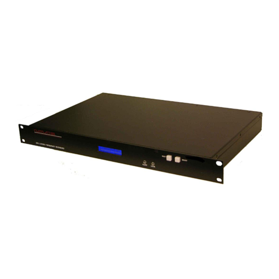
Single Channel GPS Locked OCXO
All information provide herein is the proprietary property of Novus Power Products
L.L.C. The information included may be reproduced without the permission of Novus
Power Products L.L.C. with out prior approval for purpose of operating the equipment.
Page #:
1 of 46
Users manual
Revision #:
Date:
Frequency Reference
NR2110-OG
J
3/17/17
Model NR2110-OG
www.novuspower.com
Advertisement
Chapters
Table of Contents

Related Manuals for Novus NR2110-OG


Summary of Contents for Novus NR2110-OG
- Page 1 Single Channel GPS Locked OCXO Frequency Reference All information provide herein is the proprietary property of Novus Power Products L.L.C. The information included may be reproduced without the permission of Novus Power Products L.L.C. with out prior approval for purpose of operating the equipment.
-
Page 2: Table Of Contents
Users manual NR2110-OG Revision #: Date: 3/17/17 Contents 1.0 Summary ........................4 2.0 Controls and Indicators – Front Panel ................8 2.1 GNSS Status......................9 2.2 GNSS Detailed Status ....................9 2.3 Channel Status ......................10 2.4 Status LEDs ......................11 2.5 Power Supply Status .................... - Page 3 Users manual NR2110-OG Revision #: Date: 3/17/17 Page #: 3 of 46 www.novuspower.com...
-
Page 4: Summary
Users manual NR2110-OG Revision #: Date: 3/17/17 1.0 Summary The NR2110 is a Single Channel precision GNSS/GPS locked 10MHz frequency reference. The amplifier is a low phase noise design to preserve the integrity of the reference signal. All outputs are transient and fault protected. - Page 5 Users manual NR2110-OG Revision #: Date: 3/17/17 The NR2110-OG delivers a low phase noise curve, which can be seen in the sample production test below. NR2110-OG Phase Noise Measurement Page #: 5 of 46 www.novuspower.com...
- Page 6 Users manual NR2110-OG Revision #: Date: 3/17/17 The unit features extensive reporting via the rear panel RS232 port. Equipment status, output voltage on each channel and redundancy status. By being able to monitor the output voltage, the user can detect cabling issues that cause an impedance change and replace cabling before it completely fails.
- Page 7 Users manual NR2110-OG Revision #: Date: 3/17/17 Nominal power is global AC power but a DC power option can be ordered that acts as the back-up power supply. Nominally 24 vdc, this port is used for power when AC power fails. Switching between power sources is automatic and there is no transient power outage at the equipment level.
-
Page 8: Controls And Indicators – Front Panel
Users manual NR2110-OG Revision #: Date: 3/17/17 2.0 Controls and Indicators – Front Panel This section describes the functionality of the front panel controls and indicators. Two buttons above the status LEDs provide navigation through the menus. In general, the NEXT button advances through the menus to the next screen, while the SELECT button chooses between the available values on a menu. -
Page 9: Gnss Status
Date: 3/17/17 2.1 GNSS Status On power up, the NR2110-OG will display the Time and Date as well as the current status of the GNSS receiver. If the unit is dual time based, both receivers will have status displayed. GNSS: The GNSS status indication allows the user to observe the Lock status of the receivers, and the number of GNSS satellites in view. -
Page 10: Channel Status
Users manual NR2110-OG Revision #: Date: 3/17/17 2.3 Channel Status The Channel Status can be determined by reading the actual RMS value on the output of each stage. This is compared to a threshold limit that is set by the user as a percentage variation from a saved value. -
Page 11: Status Leds
Users manual NR2110-OG Revision #: Date: 3/17/17 2.4 Status LEDs There are three status LEDs which provide a quick indication of valid unit operation. Alert LED: The Alert LED will illuminate flashing red to indicate A GNSS failure or a power supply failure. The Alert LED will not flash RED if any valid input signal is present. -
Page 12: Power Supply Status
Users manual NR2110-OG Revision #: Date: 3/17/17 2.5 Power Supply Status The Power Supply Status screen provides DC voltage values of the two available power supply sources. The 90-250V AC input is internally connected to an internal 24V AC-DC convertor which powers the internal supplies with 24V. - Page 13 Users manual NR2110-OG Revision #: Date: 3/17/17 If the optional external DC Power supply is requested, redundant power supplies will operate on either the AC input or DC input, and function independently. All functionality and reporting for an individual power supply and amplifier is independent of its redundant copy.
-
Page 14: Alert Threshold
Users manual NR2110-OG Revision #: Date: 3/17/17 2.6 Alert Threshold The Alert Threshold screen allows the user to adjust the tolerance from the Reference Voltage which, if exceeded in either direction, the output channel will report a fault status. The default threshold value is set at ±25% percent from the current state of the amplifier, and is user programmable in 5% increments, from ±10% to ±60%. - Page 15 Users manual NR2110-OG Revision #: Date: 3/17/17 The Alert Threshold can be optimized so that a channel short or an impedance change will cause an Alert. Page #: 15 of 46 www.novuspower.com...
- Page 16 Users manual NR2110-OG Revision #: Date: 3/17/17 Example: The output of channel 1 is connected to a high impedance input and reports 1.25Vrms at the output. Alert threshold is set to +/-20%. The current state is saved in the Save Configuration screen.
-
Page 17: Latch Channel Value
Users manual NR2110-OG Revision #: Date: 3/17/17 2.7 Latch Channel Value The Latch Channel Values Screen allows the user to save the current channel output value for use as the Reference Value for Alert settings. A channel Alert is triggered when the channel output voltage exceeds or falls below a percentage of the Reference Value. -
Page 18: Fault Status
Users manual NR2110-OG Revision #: Date: 3/17/17 2.9 Fault Status The Fault Status screen allows a quick overview of any Channel faults from the front panel. Press SELECT to advance to the System Fault Screen. The System Fault Screen indicates any failures in the primary system or the redundant backup system. -
Page 19: Utc Mode
Users manual NR2110-OG Revision #: Date: 3/17/17 2.10 UTC Mode The user can select how the time is displayed on the screen by choosing between three formats: UTC, 24 hour mode, or 12 hour mode. Toggle through the modes by pressing the SELECT button. -
Page 20: Power Switch
Users manual NR2110-OG Revision #: Date: 3/17/17 2.12 Power Switch The front panel Power Switch controls AC Power input to the unit. If the optional DC input is provided with 24V, or a valid DC supply, the unit will operate. In other words, if the front panel switch will not remove power if the optional DC input is powered. -
Page 21: Rear Panel
Users manual NR2110-OG Revision #: Date: 3/17/17 3.0 Rear Panel 3.1 Channel Ouput - BNC There is a single 10MHz output on the rear panel, BNC 50Ω. This can optionally be sine or square wave depending upon the factory configuration. Nominally the outputs are 50 Ohm impedance. -
Page 22: Ac Input
Users manual NR2110-OG Revision #: Date: 3/17/17 3.4 AC Input The AC input accepts 90-250Vac, 50-60Hz. IEC 320-C14 Compliant. 3.5 RS232 DB9 An RS232 port is provided for local setup, and status monitoring. The embedded processor provides status strings, as well as command responses. Configuration and status commands are detailed in the NR2110 Programmer’s Manual Section... -
Page 23: Ethernet Port / Serial-Ethernet Bridge
Users manual NR2110-OG Revision #: Date: 3/17/17 3.6 Ethernet Port / Serial-Ethernet Bridge An optional Serial-to-Ethernet bridge can be installed to handle communication remotely. The same serial commands and status output are present through the Ethernet bridge as the RS232 connection. -
Page 24: Functional Description
Users manual NR2110-OG Revision #: Date: 3/17/17 4.0 Functional Description Page #: 24 of 46 www.novuspower.com... -
Page 25: Phase Noise
Users manual NR2110-OG Revision #: Date: 3/17/17 4.1 Phase Noise Low phase noise contribution is achieved through careful PCB design, component selection and minimization of power supply noise. Below is a typical phase noise performance for a 10 MHz reference application:... -
Page 26: Outputs
Users manual NR2110-OG Revision #: Date: 3/17/17 4.2 Outputs Each output is fault and electrostatic discharge protected. Each output is independent and any output can be faulted for an indefinite period of time with no permanent damage. Each output is connected to a monitor circuit that detects a local fault on the output. -
Page 27: Built In Test
Users manual NR2110-OG Revision #: Date: 3/17/17 The base unit is configured for nine 10 MHz sine wave outputs and one PPS output. The outputs can be configured as 10 sine outputs. Low Impedance 100mA Drive 4.3 Built in Test There are number of power supplies in the design to meet special needs and noise reduction. -
Page 28: Crystal
Date: 3/17/17 5.0 Crystal Novus crystal based frequency reference products are based upon either TCXO or OCXO technology. Temperature compensated crystal oscillators will normally use a AT cut crystal and electronically compensate the device with temperature. An OCXO device uses a SC (stress compensated) crystal and the part is held at a fix temperature to minimize temperature drift. - Page 29 Users manual NR2110-OG Revision #: Date: 3/17/17 Over a broad temperature range, an AT performs very well and much easier to compensate electronically. It is also a simpler crystal to manufacture than a SC cut device. For applications where a stability of a few ppm is acceptable, a TCXO can be a cost effective alternative.
- Page 30 Users manual NR2110-OG Revision #: Date: 3/17/17 Typical OCXO Another alternative for a frequency reference is an atomic reference. These devices use a change in atomic state of an isotope of Cesium or Rubidium for stability. Instead of a stability of ±50 ppb/year for a typical OCXO- stability of ±1 ppb/year is very common.
- Page 31 Users manual NR2110-OG Revision #: Date: 3/17/17 Typical Phase Noise Performance-Rubidium with OCXO When the stability of an atomic or crystal source is not sufficient a GNSS disciplined source is an option. A GNSS receiver is installed and timing information from the GNSS is used to discipline the timing device.
- Page 32 Users manual NR2110-OG Revision #: Date: 3/17/17 Kalman Filter Performance: Page #: 32 of 46 www.novuspower.com...
- Page 33 Users manual NR2110-OG Revision #: Date: 3/17/17 Typical acceptance testing data for the NR2110-Cal GNSS Locked Reference Novus- Reference Group 201 N Forest Ave Suite 225 Independence, MO 64050 866 984 6887 Date 1/12/2015 Model NR3620-CAL Tech Serial 03150565 Actual...
-
Page 34: Calibration
3/17/17 6.0 Calibration NR2110-OG: There is an amplitude adjustment potentiometer which can be accessed through the rear panel. This is located next the Alert Relay BNC. The frequency is phase locked to the GPS signal, and no adjustment is required. -
Page 35: Programming Guide (Rs232 Port: Front And Rear)
Users manual NR2110-OG Revision #: Date: 3/17/17 7.0 Programming Guide (RS232 Port: Front and Rear) The NR2110 can accept user commands which will provide specific fault detection performance which may be customized by the user. The settings can be saved in non-volatile flash memory. -
Page 36: Rs232 Commands
Users manual NR2110-OG Revision #: Date: 3/17/17 7.1 RS232 Commands Command Setting Response Description Query Baud Rate on rear panel RS232. (Default = $BAUDNV 115200). Front Panel is 115200 baud. RS232 REAR Assign Baud rate to Rear Panel RS232 port. Default PANEL BAUD $BAUDNV=<current Baud Rate>... - Page 37 Users manual NR2110-OG Revision #: Date: 3/17/17 Setting Command Response Description $SET<nn>=n.nn Set or query the Reference Voltage for a perticular channel with respect to the active input. Use in combination with the Channel Fault Threshold Factor to define Alert on an individual Channel.
-
Page 38: Command Response
Users manual NR2110-OG Revision #: Date: 3/17/17 Setting Command Response Description $CAL<n>=nn.nn Query or set Cal Factors for specific ADC conversions. See list of Cal Factors numbered for CAL FACTORS $CAL<n>=nn.nn appropriate measurement parameters. These $CAL1=11.10 settings should only be changed by an authorized technician. -
Page 39: Status String ($Gpnvs,1) Fault Bytes
Users manual NR2110-OG Revision #: Date: 3/17/17 7.2 Status String ($GPNVS,1) Fault Bytes $GPNVS 1 hhmmss mmddyy A A nn nn 0x0000 0x00 0x00 * XX 12 13 # Description Range 1. Identifier $GPNVS 2. String ID 3. Time (UTC) hhmmss 4. -
Page 40: Status String ($Gpnvs,2) Channel Values 1-8
Users manual NR2110-OG Revision #: Date: 3/17/17 7.3 Status String ($GPNVS,2) Channel Values 1-8 $GPNVS 2 hhmmss ddmmyy n.nn n.nn n.nn n.nn n.nn n.nn n.nn n.nn * XX # Description Range 1. Identifier $GPNVS 2. String ID 3. Time (UTC) hhmmss 4. -
Page 41: Status String ($Gpnvs,3) Power Supply Values
Users manual NR2110-OG Revision #: Date: 3/17/17 7.4 Status String ($GPNVS,3) Power Supply Values $GPNVS 3 hhmmss ddmmyy n.nn n.nn n.nn n.nn n.nn n.nn n.nn n.nn * XX # Description Range 1. Identifier $GPNVS 2. String ID 3. Time (UTC) hhmmss 4. -
Page 42: Status String ($Gpnvs,4) Channel Values 9-16
Users manual NR2110-OG Revision #: Date: 3/17/17 7.5 Status String ($GPNVS,4) Channel Values 9-16 $GPNVS 2 hhmmss ddmmyy n.nn n.nn n.nn n.nn n.nn n.nn n.nn n.nn * XX # Description Range 1. Identifier $GPNVS 2. String ID 3. Time (UTC) hhmmss 4. -
Page 43: Technical Specification
Optional PPS 15ns RMS accuracy, 3.3 volt logic SMA female – Internal 3.3V Supply, 45mA max. Antenna Novus NA-103 or Novus NA-106 Power 90 to 250 vac, 50/60hz, IEC 320-C14 Alert 20Vdc/Vac, 0.5 amp relay contacts- relay closed for normal condition, BNC Weight 5.5 lbs... -
Page 44: Limited Hardware Warranty
Should Novus be unable to repair or replace the product within a reasonable amount of time, the customer’s alternate remedy shall be a refund of the purchase price upon return of the product to Novus. The liability of NOVUS under this warranty is limited to replacing, repairing or issuing a credit, at its option, for any such item returned by Buyer under the terms of this warranty. - Page 45 3/17/17 LIMITATION OF REMEDIES: REGARDLESS OF WHETHER ANY REMEDY SET FORTH HEREIN FAILS OF ITS ESSENTIAL PURPOSE, IN NO EVENT WILL NOVUS BE LIABLE TO YOU FOR ANY SPECIAL, CONSEQUENTIAL, INDIRECT OR SIMILAR DAMAGES, INCLUDING, WITHOUT LIMITATION, DAMAGES FOR LOSS OF BUSINESS PROFITS, BUSINESS INTERRUPTION, LOSS OF DATA OR BUSINESS...
-
Page 46: Appendix: Gnss Command Reference
Users manual NR2110-OG Revision #: Date: 3/17/17 10.0 Appendix: GNSS Command Reference See attached. Page #: 46 of 46 www.novuspower.com... - Page 47 GPS/GNSS Receiver Communications Specification NMEA-0183 All information provided herein is the proprietary property of Novus Power Products L.L.C. The information included may be reproduced without the permission of Novus Power Products L.L.C. without prior approval for purpose of operating the equipment.
- Page 48 Users manual Appendix A Revision #: Date: 07-14-15 Table of Contents: COMMUNICATION SPECIFICATION ......................... 4 SERIAL DATA OUTPUT TIMING △4........................... 5 NMEA SENTENCE FORMAT ............................. 6 PROPRIETARY SENTENCE FORMAT: ........................7 STANDARD NMEA OUTPUT SENTENCES ........................8 GGA – G : ......................
- Page 49 Users manual Appendix A Revision #: Date: 07-14-15 PROPRIETARY NMEA OUTPUT SENTENCES ......................40 ACK – O : ......................40 UTPUT THE OMMAND ECEPTION HECK ORMAT CR – ERIDE GNSS CORE LIBRARY INTERFACE ...................... 41 ) △4△5 F CRW(TPS1) – O : ..........
- Page 50 Users manual Appendix A Revision #: Date: 07-14-15 Communication Specification Signal Lines used: TXD, RXD Flow Control: None System: Full Duplex Asynchronous Speed: Configurable, Default 38400 bps (*1) Start Bit: 1 bit Data Length: 8 bits Stop Bit: 1 bit Parity Bit: None Data Output Interval:...
- Page 51 Users manual Appendix A Revision #: Date: 07-14-15 Serial data output timing △ The output timing of serial data is synchronous with PPS output timing. Serial data is begun to output in the 25ms to 75ms range after PPS is output. The time of serial data indicates next PPS output timing.
- Page 52 Users manual Appendix A Revision #: Date: 07-14-15 NMEA Sentence Format 13.1 Standard Sentence Format: <address field> <data field> … *<checksum field> <CR> <LF> 5 bytes Field Description Start-of Sentence marker <address field> 5-byte fixed length. First 2 bytes represent a talker ID, and the remaining 3 bytes do a sentence formatter.
- Page 53 Users manual Appendix A Revision #: Date: 07-14-15 Proprietary Sentence Format: $ P <maker ID> <sentence type> , <data field> … *<checksum field> <CR> <LF> 3 bytes 3 bytes Field Description Start-of-Sentence marker Proprietary sentence identifier 3-byte fixed length. <maker ID> GT-87’s maker ID is “ERD”...
- Page 54 Users manual Appendix A Revision #: Date: 07-14-15 Standard NMEA Output Sentences The receiver supports eight standard NMEA output sentences (GGA, GLL, GNS, GSA, GSV, RMC, VTG and ZDA) per NMEA standard 0183 Version 4.10 (June, 2012). By default, the RMC, GNS, GSA, ZDA, GSV and TPS sentences will be output every second. The sentences can be independently enabled and disabled using the $PERDCFG,NMEAOUT and/or $PERDAPI,CROUT command described later in this document, as well as use differing transmission rates.
- Page 55 Users manual Appendix A Revision #: Date: 07-14-15 – Global Positioning System Fix Data Format: $XXGGA , hhmmss.sss , ddmm.mmmm , , dddmm.mmmm , <CR> <LF> Description Range “hh”: hour 00 - 23 “mm”: minute 00 - 59 “ss.sss”: second 00.000 - 59.999 2-3.
- Page 56 Users manual Appendix A Revision #: Date: 07-14-15 – △ Geographic Position - Latitude/Longitude Format: $XXGLL , ddmm.mmmm , a , dddmm.mmmm , , hhmmss.sss , a , a *hh <CR> <LF> Description Range 1-2. Latitude “dd”: degree 00 - 90 “mm.mmmm”: minute 00.0000 - 59.9999 “a”: North/South...
- Page 57 Users manual Appendix A Revision #: Date: 07-14-15 – GNSS Fix Data Format: $XXGNS , hhmmss.sss , ddmm.mmmm , , dddmm.mmmm , , c--c , <CR> <LF> Description Range “hh”: hour 00 - 23 “mm”: minute 00 - 59 “ss.sss”: second 00.000 - 59.999 Latitude 2-3.
- Page 58 Users manual Appendix A Revision #: Date: 07-14-15 △ – GNSS DOP and Active Satellites Format: $XXGSA , a , a , xx , xx , xx , … , xx , x.x , x.x , x.x , h *hh <CR> <LF> 6-13 Description Range...
-
Page 59: Gsv Gnss Satellites In View
Users manual Appendix A Revision #: Date: 07-14-15 △ – GNSS Satellites in View Format: $XXGSV <CR> <LF> Description Range Total number of messages 1 - 4 Number of messages 1 - 4 Number of satellites in line-of-sight 00 - 14 Sat. - Page 60 Users manual Appendix A Revision #: Date: 07-14-15 Satellite number from 93 to 99 indicates QZSS (193 to 199) Page 14 of 58...
- Page 61 Users manual Appendix A Revision #: Date: 07-14-15 △ – Recommended Minimum Navigation Information Format: $XXRMC , hhmmss.sss , a , ddmm.mmmm , a , dddmm.mmmm , a , x.x , , ddmmyy , <CR> <LF> # Description Range “hh”: hour 00 - 23 “mm”: minute 00 - 59...
- Page 62 Users manual Appendix A Revision #: Date: 07-14-15 Example: $GNRMC,012344.000,A,3442.8266,N,13520.1233,E,0.00,0.00,191132,,,D,V*0B UTC: 01:23:44.000 Differential 34 deg 42.8266 min N 135 deg 20.1233 min E Speed: 0.0 kts True Course: 0.0 degrees UTC Date: Nov 19, 2032 Page 16 of 58...
- Page 63 Users manual Appendix A Revision #: Date: 07-14-15 – Course Over Ground and Ground Speed Format: $XXVTG , *hh <CR> <LF> # Description Range 1-2. True Course (degree) “T” (meaning TRUE) 3-4. Magnetic Direction “M” (meaning Magnetic Direction) Note: A null field is output unless magnetic direction information is available. 5-6.
- Page 64 Users manual Appendix A Revision #: Date: 07-14-15 Proprietary NMEA Input Sentences These sentences are input commands for the protocol of this receiver. Page 18 of 58...
- Page 65 Users manual Appendix A Revision #: Date: 07-14-15 △ △ – GNSS Satellite System Configuration Format: $PERDAPI , GNSS , talkerID , , glonass , galileo , qzss sbas *hh <CR> <LF> Contents Range Default Remark GNSS Command Name AUTO: GLGSV is omitted in case of no glonass. AUTO, GPGSV is omitted in case of no GPS, SBAS and LEGACYGP...
- Page 66 Users manual Appendix A Revision #: Date: 07-14-15 △ – FIXMASK Setting of Positioning and Satellite Mask Format: $PERDAPI , FIXMASK , mode elevmask , Reserve1 snrmask , Reserve2 [, Prohibit SVs Prohibit SVs Prohibit SVs Prohibit SVs Prohibit SVs *hh <CR>...
- Page 67 Users manual Appendix A Revision #: Date: 07-14-15 Example: $PERDAPI,FIXMASK,USER,10,0,37,0,0x92,0x01,0x00,0x00,0x20000*50 Elevation mask: 10 degrees Signal level mask: 37 dBHz GPS mask: GPS (BIT2 = SVID 2), GPS (BIT5 = SVID 5) and GPS (BIT9 = SVID 9) GLONASS mask: GLONASS (BIT1 = SVID 65) SBAS mask: SBAS (BIT18 = SVID 50) Notes: - It is applied not only to First Fix or the time of a positioning return but to all the positioning.
- Page 68 Users manual Appendix A Revision #: Date: 07-14-15 ( ) – △ Setting of PPS Pulse per second 4 Format: $PERDAPI , PPS , type , mode , period , pulse width , cable delay , polarity [, PPS accuracy threshold] *hh <CR <LF>...
- Page 69 Users manual Appendix A Revision #: Date: 07-14-15 Notes: △ - LEGACY PPS setting is output legacy PPS which is not synchronized with frequency which is output from GCLK pin, but which is output immediately after first fix in case of cold start. - GCLK PPS setting is output GCLK PPS which synchronized with frequency which is output from GCLK pin, but it takes some to become GCLK PPS steady after first fix (typically, 1~2 minutes after fist fix).
- Page 70 Users manual Appendix A Revision #: Date: 07-14-15 △ RESTART - Restart command 4 Format: $PERDAPI , RESTART , restart mode *hh <CR> <LF> Contents Range Default Remark RESTART Command Name restart WARM Restart mode mode COLD FACTORY Example: $PERDAPI,RESTART,COLD*08 Mode: cold restart Notes: △...
- Page 71 Users manual Appendix A Revision #: Date: 07-14-15 – △ TIME Setting of time information Initial time is configured. The setting of time is effective only within the case that time is not decided by other factors. A setting of a millennium which is the times of GPS week rollover is received also after time decision.
- Page 72 Users manual Appendix A Revision #: Date: 07-14-15 – △ TIMEZONE Local Zone Time This sentence is reflected to ZDA sentence (not only local zone field but also UTC time field). Format: $PERDAPI TIMEZONE , sign , hour , minute *hh <CR> <LF> Contents Range Default...
- Page 73 Users manual Appendix A Revision #: Date: 07-14-15 – △ SURVEY Position Mode 1 Format: $PERDAPI , SURVEY , position mode [, sigma threshold , time threshold] latitude longitude altitude]] *hh <CR> <LF> Contents Range Default Remark SURVEY Command Name 0: Normal NAV (navigation) mode 1: Position Survey...
- Page 74 Users manual Appendix A Revision #: Date: 07-14-15 Fixed position: 37.78700 degrees north 122.45100 degrees west Altitude: 31.5 m Page 28 of 58...
- Page 75 Users manual Appendix A Revision #: Date: 07-14-15 Notes: - It is omissible after the 3rd field. - When the position mode is “1”, a position is re-calculated after power supply OFF/ON. Please use it, when the antenna position may change before power supply OFF. - When the position mode is “2”, after power supply OFF/ON, the estimated position that calculated before power supply OFF is kept, and the position is updated.
- Page 76 Users manual Appendix A Revision #: Date: 07-14-15 The condition of survey is satisfied. [*] Position mode is always started by time only mode if TO Keep mode by this condition and power off. Page 30 of 58...
- Page 77 Users manual Appendix A Revision #: Date: 07-14-15 – △ △ FREQ Setting of GCLK FREQUENCY 7 Format: $PERDAPI , FR , mode , freq [, duty offset] *hh <CR> <LF> Contents Range Default Remark FREQ Command Name 0 : stop mode 0 to 1 1 : output...
- Page 78 Users manual Appendix A Revision #: Date: 07-14-15 – △ △ DEFLS Setting of default leap second 6 Format: $PERDAPI , DEFLS , [, mode] *hh <CR> <LF> Contents Range Default Remark DEFLS Command Name 0 to 32 Default leap second AUTO: default leap second is updated automatically AUTO or mode...
- Page 79 Users manual Appendix A Revision #: Date: 07-14-15 TIMEALIGN – setting of time alignment △ 4 Format: $PERDAPI , TIMEALIGN , mode *hh <CR> <LF> Contents Range Default Remark TIMEALIGN Command Name 1 : GPS alignment mode 1 to 3 2 : UTC(USNO) alignment 3 : UTC(SU) alignment Example:...
- Page 80 Users manual Appendix A Revision #: Date: 07-14-15 Restriction: Output time GLONASS only fix GPS only fix setting GPS + GLONASS setting setting accurate default GPS alignment leap second is required [*1] UTC(USNO) alignment UTC(SU) alignment GLONASS only fix GPS + GLONASS setting GPS only fix setting setting GPS alignment...
- Page 81 Users manual Appendix A Revision #: Date: 07-14-15 – △ FLASHBACKUP Setting of backup in Flash 4 Format: $PERDAPI , FLASHBACKUP , type *hh <CR> <LF> Contents Range Default Remark FLASHBACKUP Command Name Target of backup Each bit represents one command setting 0x00 to 0x01 : FREQ command setting type...
- Page 82 Users manual Appendix A Revision #: Date: 07-14-15 – CROUT Setting of CR Output Format: $PERDAPI , CROUT , type rate *hh <CR> <LF> Contents Range Default Remark CROUT Command Name Output CR sentence type N,M,W,X,Y,Z W,X,Y,Z [*] Alphabets of outside range are reserved.
- Page 83 Users manual Appendix A Revision #: Date: 07-14-15 CFG – Setting of Application Software – △ NMEAOUT Standard NMEA Output Format: $PERDCFG , NMEAOUT , type , interval *hh <CR> <LF> Contents Range Default Remark NMEAOUT Command Name Standard NMEA sentence [*1] type [*1]...
- Page 84 Users manual Appendix A Revision #: Date: 07-14-15 - In case of using low baud rate, please adjust size of output sentence by NMEAOUT command and CROUT command to output all sentence within one second. Page 38 of 58...
- Page 85 Users manual Appendix A Revision #: Date: 07-14-15 – PVT System VERSION – Software Version Format: $PERDSYS VERSION <CR> <LF> Contents Range Default Remark VERSION Command Name Example: $PERDSYS,VERSION*2C – GPIO General Purpose Input/output Format: $PERDSYS GPIO <CR> <LF> Contents Range Default Remark...
-
Page 86: Proprietary Nmea Output Sentences
Users manual Appendix A Revision #: Date: 07-14-15 Proprietary NMEA Output Sentences This sentence is a protocol only for our company. It starts from “$PERD” which shows that it is an original sentence. – Output the Command Reception Check Format: $PERDACK , command , sequence , subcommand *hh <CR>... -
Page 87: Cr - Eride Gnss Core Library Interface
Users manual Appendix A Revision #: Date: 07-14-15 CR – e GNSS Core Library Interface Ride CRW(TPS1) – Output Time Transfer Info per Second (Date and leap second) △ △ 5 Format: $PERDCRW , TPS1 , Date & Time , time status , update date , present LS , future LS , pps status... - Page 88 Users manual Appendix A Revision #: Date: 07-14-15 Pps status: present pps is sync with UTC (USNO) Page 42 of 58...
- Page 89 Users manual Appendix A Revision #: Date: 07-14-15 Notes: - This command is output every second. - Present LS is current leap second. This is updated in the timing of leap second update schedule. - $PERDAPI,CROUT,W,0*4F stops outputting this command. - Update data indicate zero when no update schedule.
-
Page 90: (Pps) △4 Format
Users manual Appendix A Revision #: Date: 07-14-15 – △ CRX(TPS2) Output Time Transfer Info per Second (PPS) 4 Format: $PERDCRX , TPS2 , pps status , pps mode , pps period , pulse width , cable delay , polarity , pps type , estimated accuracy , Sawtooth , pps acc threshold *hh <CR> <LF> Contents Range Default... - Page 91 Users manual Appendix A Revision #: Date: 07-14-15 $PERDCRX,TPS2,1,2,0,200,+001000,0,0,0005,+0.000,1000*29 PPS status: PPS ON (1) PPS mode: during on fix (2) PPS period: 1PPS (0) PPS pulse width: 200ms PPS cable delay: +1000ns Polarity: rising edge Type: LEGACY PPS Estimated accuracy: 5ns Sawtooth: +0.000ns PPS estimated accuracy threshold: 1us Notes:...
- Page 92 Users manual Appendix A Revision #: Date: 07-14-15 – CRY(TPS3) Output Time Transfer Info per Second (Survey & TRAIM) Format: $PERDCRY , TPS3 , pos mode , sigma , sigma threshold , time , time threshold , TRAIM solution , TRAIM status Removed SVs Receiver status...
- Page 93 Users manual Appendix A Revision #: Date: 07-14-15 $PERDCRY,TPS3,2,0003,001,002205,086400,0,0,00,0x00000000*68 Positioning mode: Survey mode (calculation continuously) (2) Survey sigma: 3 [m] Survey sigma threshold: 1 [m] Survey time: 2205 [seconds] Survey time threshold: 86400 [seconds] TRAIM solution: OK (0) TRAIM status: OK (0) Removed SVs: 0 Receiver status: 0x00000000 Notes:...
-
Page 94: (Frequency) △3 Format
Users manual Appendix A Revision #: Date: 07-14-15 – △ CRZ (TPS4) Output Time Transfer Info per Second (FREQUENCY) 3 Format: $PERDCRZ , TPS4 , freq mode , Freq status , GCLK accuracy , lock cnt lockoff cnt , reserve , IDtag , GCLK setting 1 , GCLK setting 2 *hh <CR>... - Page 95 Users manual Appendix A Revision #: Date: 07-14-15 $PERDCRZ,TPS4,1,1,0,+000000,+000000,+000000,+000000,000000,000000,0x15,0000*57 Freq mode: warm up Freq status: output GCLK accuracy: accurate Notes: - This command is output every second. - $PERDAPI,CROUT,Z,0*42 stops outputting this command. Page 49 of 58...
-
Page 96: Crm - Measurement Data Of Gps
Users manual Appendix A Revision #: Date: 07-14-15 CRM – Measurement Data of GPS Format: $PERDCRM time sennum maxsen system svid reserve , doppfreq , pseudorange <CR> <LF> Contents Range Default Remark time 0 to 604799 GPS time of week Sentence number sennum 1 to 32... -
Page 97: Crn - Navigation Data
Users manual Appendix A Revision #: Date: 07-14-15 CRN – Navigation Data Format: $PERDCRN system svid subframe data <CR> <LF> Contents Range Default Remark system GNSS system ID (1=GPS) Satellite number svid 1 to 99 10 words Subframe data no parirt included subframe data (60 strings) Example:... -
Page 98: Sys - Answer Of Pvt System
Users manual Appendix A Revision #: Date: 07-14-15 SYS – Answer of PVT System ERSION- Software Version 7.3.1 Format: $PERDSYS , VERSION , device version , reserve1 , reserve2 <CR> <LF> Contents Range Default Remark VERSION Command Name device Device Name Version number version reserve1... -
Page 99: Fixsession- Fix Session △1 Format
Users manual Appendix A Revision #: Date: 07-14-15 △ FIXSESSION- Fix Session 1 Format: $PERDSYS , FIXSESSION , reserve1 [, reserve2 , reserve3] <CR> <LF> Contents Range Default Remark FIXSESSION Command Name reserve1 reserve field reserve2 reserve field reserve3 reserve field Example: $PERDSYS,FIXSESSION,ON,19015,19.015*7C Notes:... -
Page 100: Bbram - Battery Backup Random Access Memory △1 Format
Users manual Appendix A Revision #: Date: 07-14-15 △ BBRAM - Battery Backup Random Access Memory 1 Format: $PERDSYS BBRAM reserve1 [, reserve2] <CR> <LF> Contents Range Default Remark BBRAM Command Name reserve1 reserve field reserve2 reserve field Example: $PERDSYS,BBRAM,PASS*15 Notes: eRide - This string is sent when certain events occur. -
Page 101: Backup Of The Receiver Parameters (For Bbram) △4
Users manual Appendix A Revision #: Date: 7-13-15 Backup of the Receiver Parameters (for BBRAM) △ The parameters which this receiver has backed up are shown below. Chart. Backup of the receiver parameter POWER CONTENTS PARAMETER WARM COLD FACTORY OFF/ON Date &... - Page 102 Users manual Appendix A Revision #: Date: 7-13-15 TIMEALIGN Time alignment FLASHBACKUP Backup in flash Chart. Backup of the configure parameter of command COMMAND POWER PARAMETER WARM COLD FACTORY NAME OFF/ON UART1 Baud rate of UART1 NMEA output NMEAOUT interval [*1] The position calculated by position survey mode or input by $PERDAPI,SURVEY,3.
- Page 103 Should Novus be unable to repair or replace the product within a reasonable amount of time, the customer’s alternate remedy shall be a refund of the purchase price upon return of the product to Novus. The liability of NOVUS under this warranty is limited to replacing, repairing or issuing a credit, at its option, for any such item returned by Buyer under the terms of this warranty.
- Page 104 Date: 7-13-15 OF OR INABILITY TO USE THE HARDWARE SUPPLIED THEREWITH EVEN IF NOVUS OR ANYONE ELSE HAS BEEN ADVISED OF THE POSSIBILITY OF SUCH DAMAGES, OR FOR ANY CLAIM BY ANY OTHER PARTY. EXCLUDED DAMAGES SHALL INCLUDE, BUT ARE NOT LIMITED TO: COSTS OF REMOVAL AND INSTALLATION, LOSSES SUSTAINED AS THE RESULT OF INJURY TO ANY PERSON, OR DAMAGE TO PROPERTY.
Need help?
Do you have a question about the NR2110-OG and is the answer not in the manual?
Questions and answers