
Related Manuals for Omron E3T-ST Series


Summary of Contents for Omron E3T-ST Series
- Page 1 E3T-ST□/FT□ series Photoelectric sensor Information for ISO13849-1 Compliance Man No. Z484-E1-01...
- Page 2 Thank you for selecting OMRON product. When the product is treated as ISO 13849-1 (Cat 1, PL c), please confirm the following: Before operating the product, please read both this document and the 'Instruction Manual' included with the product together to acquire sufficient product knowledge. It is convenient to keep these...
- Page 3 Data presented in Omron Company websites, catalogs and other materials is provided as a guide for the user in determining suitability and does not constitute a warranty. It may represent the result of Omron’s test conditions, and the user must correlate it to actual application requirements.
-
Page 4: Table Of Contents
Table of contens 1.Product function .......................5 1.1 Timing chart .........................6 1.2 Control output/ Operation mode ..................7 1.3 Dimensions ........................8 1.4 Mounting distance ......................9 2. Safety Precautions ......................11 2.1 Warning ........................12 2.2 Precautions for Safe Use....................12 2.3 Precautions for Correct Use ..................13 3.Information of standards .................... -
Page 5: 1.Product Function
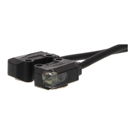
1.Product function E3T-ST□/FT□ series is “Through-beam photoelectric sensor which detects objects that either reflect or interrupt visible or invisible light. The control output is a semiconductor switching element. Detection object Emitter Receiver Sensing method Through-beam Appearance Rectangular type(Side-view) Rectangular type(Flat) Item Light-ON E3T-ST31... -
Page 6: Timing Chart
Light ON Light incident 1.1 Timing chart Light interrupted The light-operated and dark-operated timing charts are shown in Figure. Operation indicator Light ON Light incident Output transister state Light interrupted HIGH Operation indicator OUT voltage(NPN type) HIGH Output transister state OUT voltage(PNP type) Dark ON ⇔... -
Page 7: Control Output/ Operation Mode
1.2 Control output/ Operation mode Control output is 2 type which is NPN output and PNP output. The operating mode, time chart, and output circuit are shown in the figure below. The conditions under which the control output is turned on are different. Operation mode Output of Light-ON Output of Dark-ON... -
Page 8: Dimensions
1.3 Dimensions... -
Page 9: Mounting Distance
1.4 Mounting distance Do not use the sensor system with mirrors in a retro-reflective configuration. When using more than 1 set of E3T-ST□/FT□ in adjacent areas, the emitter of one E3T-ST□/FT□ may interfere with the receiver of the other, causing the safety functions to stop working properly. Install and configure them so that mutual interference does not occur. - Page 10 Infrared LED E3T-ST1□(M)F+E39-S63 E3TT-ST2□(M)F+E39-S63 E3T-ST3□(M)F+E39-S63 E3T-FT1□F+E39-S64 E3T-FT2□F+E39-S64...
-
Page 11: 2. Safety Precautions
2. Safety Precautions The E3T-ST□ and E3T-FT□ series conforms to the international standard ISO 13849-1 (Cat 1, PL c). Before operating the product, please read both this document and the 'Instruction Manual' included with the product together to acquire sufficient product knowledge. The following notation is used in this manual to provide precautions required to ensure safe usage of a E3T-ST□... -
Page 12: Warning
2.1 Warning Do not connect the E3T to an AC or DC power supply with higher voltage than nominal DC24V. Otherwise the sensor may explode, burn, or cause electric shock. Do not use this product for an application where it directly detects the human body. Use an opaque test rod with 3mm in diameter. -
Page 13: Precautions For Correct Use
2.3 Precautions for Correct Use Precautions for Correct Use Do not use the product in atmospheres or environments that exceed product ratings. Wiring The maximum power supply voltage is 26.4 VDC. Before turning the power ON, make sure that the power supply voltage is not more than maximum voltage. - Page 14 Use of E39-E10 Sensitivity Adjustment Unit (Dark-ON: E3T-ST12) 1. Mount the Unit on the Receiver. 2. Set the adjuster of the Sensitivity Adjustment Unit to Max. (Before shipping: Max.) 3. After mounting on the Sensor, adjust the optical axis and secure the Sensor. 4.
-
Page 15: 3.Information Of Standards
3.Information of standards E3T-ST□/FT□ series applies with the following standards. Compliant Standards - EMC: IEC60947-5-2:2019 - Low Voltage: IEC60947-5-2:2019 3.2 Certification Standards TUV: ISO13849-1:2023(Cat 1, PL c),IEC60947-5-2:2019 3.3 Safety states In case of E3T-ST/FT failure, safety state is Output transistor OFF. Safety-related parameters Parameter □... -
Page 16: 4.Maintenance Checklist
4.Maintenance Checklist □ □ Please perform daily and periodic inspections for all E3T-ST units. Operating this device without performing the inspection or without removing the abnormal condition may cause death or serious injury. 4.1 Daily Inspection Checklist Control output shall operate as follows: ... -
Page 17: 5.Troubleshooting
5.Troubleshooting If the product is not operating or if there are abnormalities such as the output not switching ON/OFF, please take the following measures. Unit Trouble Contents Cause and measures Emitter Emitter is not emitting There may be no power supply voltage. red light. -
Page 18: 6.Revision History
6.Revision History Revision Revision date Revisions symbol April, 2024 First release...
Need help?
Do you have a question about the E3T-ST Series and is the answer not in the manual?
Questions and answers