
Subscribe to Our Youtube Channel
Related Manuals for Crestron DM NAX Series


Summary of Contents for Crestron DM NAX Series
- Page 1 View this document in HTML crestron.com/docs/9045 Product Manual DM NAX® Audio-over-IP Distribution Platform Crestron Electronics, Inc.
- Page 2 Other trademarks, registered trademarks, and trade names may be used in this document to refer to either the entities claiming the marks and names or their products. Crestron disclaims any proprietary interest in the marks and names of others.
-
Page 3: Table Of Contents
Contents Overview Features Products DM-NAX-2XLRI-1G DM-NAX-8ZSA Physical Description Applications DM-NAX-16AIN Physical Description Application DM-NAX-4ZSA-50 DM-NAX-4ZSP Physical Description DM-NAX-AMP-X300 DM-NAX-AUD-IO DM-NAX-AUD-USB DM-NAX-BTIO-1G Specifications DM-NAX-2XLRI-1G Specifications Specifications Dimension Drawing DM-NAX-8ZSA Specifications Specifications Dimension Drawing DM-NAX-4ZSA-50 Specifications Specifications Dimension Drawing DM-NAX-4ZSP Specifications Specifications Dimension Drawing DM-NAX-16AIN Specifications Specifications... - Page 4 Dimension Drawing DM-NAX-BTIO-1G Specifications Specifications Dimension Drawing Installation DM-NAX-2XLRI-1G Installation In the Box Mounting the Device Connect the Device Reset the Device DM-NAX-8ZSA Installation In the Box Install the Device Connect the Device Apple® AirPlay® Setup Spotify® Connect Setup Observe the LED Indicators Reset the Device DM-NAX-4ZSA-50 Installation In the Box...
- Page 5 Reset the Device Configuration DM-NAX-2XLRI-1G Web Interface Configuration Action Status Settings Security 802.1x Configuration Access the Web Interface With the Crestron Toolbox™ Application DM-NAX-8ZSA Web Interface Configuration Action Status Settings Security 802.1x Configuration Access the Web Interface With the Crestron Toolbox™ Application...
- Page 6 Web Interface Configuration Action Status Settings Security 802.1x Configuration Access the Web Interface With the Crestron Toolbox™ Application DM-NAX-16AIN Web Interface Configuration Action Status Settings Security 802.1x Configuration Access the Web Interface With the Crestron Toolbox™ Application DM-NAX-AMP-X300 Web Interface Configuration...
- Page 7 802.1x Configuration Access the Web Interface With the Crestron Toolbox™ Application Resources Crestron Support and Training Programmer and Developer Resources Product Certificates Product Manual — Doc. 9045M Contents • v...
-
Page 8: Overview
Overview DM NAX® Audio-over-IP (AoIP) solutions are built on AES67 standards with the additional ease of configuration via a web interface, SIMPL, C#, and/or a RESTful API. It is compatible with DM NVX® endpoints through an AES67 secondary audio stream, and also with third-party AES67 solutions, including Dante®... -
Page 9: Dm-Nax-2Xlri-1G
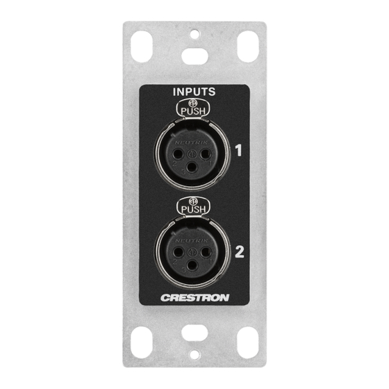
The DM-NAX-2XLRI-1G provides a single-gang wall mount for (2) XLR inputs. The rear of the wall plate features an Ethernet connection for power and DM NAX® audio-over-IP (AOIP) networking. The rear panel also features a five-pin line-level audio output for transmitting an audio signal to a Crestron media wall plate (MP-WP-2XLRO-1G and MP-WP-2RCAO-1G). - Page 10 Line Level and Microphone Level Support The front panel XLR connectors of the DM-NAX-2XLRI-1G can be configured for either line level or microphone level input. Each XLR input can be configured to send a +48V phantom power signal to power a connected condenser microphone. Digital Signal Processing (DSP) DSP capabilities such as a 5-band EQ per XLR input and level control of all input and output signal types are available to configure via the web user interface.
-
Page 11: Dm-Nax-8Zsa
DM-NAX-8ZSA The Crestron DM-NAX-8ZSA is a next generation DM NAX® Audio-over-IP (AoIP) amplifier that puts Crestron multiroom audio distribution on the network. It provides eight amplified stereo zone (16- channel) outputs. Four stereo line-level outputs mirror speaker zone outputs 1-4. - Page 12 PWR: (1) LED, indicates operating power is supplied; illuminates amber while ❶ booting, white when powered on, red when in standby (no audio or LAN connection), and off when no power is supplied. LAN: (1) LED, illuminates white when the amplifier is connected to a network ❷...
- Page 13 Rear Panel The following illustration shows the rear panel of the DM-NAX-8ZSA. DIGITAL INPUTS: (2) JIS F05 female TOSLINK® optical fiber connectors, S/PDIF ❶ optical digital audio inputs; (2) RCA female; S/PDIF coaxial digital audio inputs; Input Impedance: 75 Ω ANALOG INPUTS: (8) RCA female comprising (4) unbalanced stereo line-level audio ❷...
- Page 14 Ethernet 2: (1) 8-pin RJ-45 connector, female; 100BASE-TX/1000BASE-T Ethernet port; Green LED indicates Ethernet link status; Flashing amber LED indicates Ethernet activity SETUP: (1) Push button: Pressing and holding the SETUP button for 15 seconds with ❽ power supplied clears network settings and restores the default DHCP mode; Pressing and holding the SETUP button with power disconnected, then connecting the power supply and continuing to hold SETUP button for 30 seconds performs a factory restore;...
-
Page 15: Applications
Applications This section shows DM-NAX-8ZSA device in multizone applications. 8 • DM NAX® Product Manual — Doc. 9045M... - Page 16 NOTES: DM NAX devices generate multicast traffic on the network. Even a single DM NAX device connected to an unmanaged network can cause communication issues with other devices connected to the same network. For information on system installation, refer to the DM NAX®...
- Page 17 This application diagram shows the following setup: Up to eight zones of amplification and audio distribution Local line level input Local line level output to an AVR mirroring a zone of amplification Available music streaming services on up to eight DM NAX zones The DM-NAX-16AIN is used to transmit audio from the DM chassis’...
- Page 18 This application diagram shows different 2.1 configurations and how they affect the zone count of an DM-NAX-8ZSA. By default, a zone comprises two speaker outputs (a left and a right). The 2.1 configuration at the left of the diagram comprises two speaker outputs, with an additional line output that feeds the subwoofer.
- Page 19 Having higher output-count zone configurations on a single DM-NAX-8ZSA will affect the total available zone count on a given box. For example, if you have a single bridged 2.1 configuration on an DM-NAX-8ZSA, it will lower the maximum zone count to six, as the bridged 2.1 consumes three zones worth of speaker outputs on its own.
- Page 20 Bussing to multiple zones to feed a large group of low-impedance speakers with the same signal and shared controls This application diagram shows a commercial setup using casting service streaming applications. For example, in a hotel, each room can receive a cast from a third-party device. The Lobby and Pool zones can exist on another DM-NAX-8ZSA unit that is on the same LAN or on a separate VLAN or WAP to cast to/control those zones.
- Page 21 This application diagram shows zones using only the line outputs. Line outputs 1 and 2 feed high impedance amplifiers driving speakers for large outdoor spaces and speaker zone outputs 5-8 feed low- impedance indoor spaces without overlap of signals. The LAN cloud shows that any individual applications can exist as part of a large DM NAX system.
-
Page 22: Dm-Nax-16Ain
The Crestron DM NAX® Audio-over-IP (AoIP) encoder (DM-NAX-16AIN) provides 16 local stereo audio inputs to a DM NAX Crestron multiroom audio distribution network. It provides 8 digital inputs comprised of 4 SPDIF TOSLINK® connectors and 4 SPDIF coaxial connectors. Each digital input supports 2-channel PCM audio. - Page 23 Rear Panel The following illustration shows the rear panel of the DM-NAX-16AIN. ANALOG INPUTS: (8) RCA female comprising (4) unbalanced stereo line-level ❶ audio inputs; (4) 5-pin phoenix balanced connector; Input Impedance: 10000 Ω; Maximum Input Level: 2 Vrms DIGITAL INPUTS: (4) JIS F05 female TOSLINK® optical fiber connectors, S/PDIF ❷...
- Page 24 GROUND: 6-32 screw, chassis ground lug ❼ Product Manual — Doc. 9045M DM NAX® • 17...
-
Page 25: Application
Application This section shows DM-NAX-16AIN device in a multizone application. This application diagram shows the following setup: Up to eight zones of amplification and audio distribution Local line level input Local line level output to an AVR mirroring a zone of amplification Available music streaming services on up to eight DM NAX zones The DM-NAX-16AIN is used to transmit audio from the DM chassis’... -
Page 26: Dm-Nax-4Zsa-50
DM-NAX-4ZSA-50 The Crestron DM-NAX-4ZSA-50 is a next generation DM NAX® Audio-over-IP (AoIP) amplifier that puts Crestron multiroom audio distribution on the network. It provides four amplified stereo zone (8- channel) outputs and an independent line level zone (2-channel) output. A dedicated streaming service player for each of the four zones enables complete freedom to stream different content in every zone. - Page 27 The amplifier is high-density stackable with other Crestron DM NAX or X-Series amplifiers, allowing multiple units to be installed vertically in an equipment rack without needing extra ventilation space. Rack mount parts are included, so no additional mounting accessories or rack shelves are required.
-
Page 28: Dm-Nax-4Zsp
DM-NAX-4ZSP The Crestron DM-NAX-4ZSP is a next generation Audio-over-IP (AoIP) preamplifier that puts Crestron multiroom audio distribution on the network. It provides four stereo zone (8-channel) line-level outputs. A dedicated streaming service player enables streaming different content in each of the four zones. - Page 29 PWR: (1) LED, indicates operating power is supplied; illuminates white when ❶ powered on, red when in standby (no audio or LAN connection), and off when no power is supplied. LAN: (1) LED, illuminates white when the device is connected to a network with a ❷...
- Page 30 Rear Panel The following illustration shows the rear panel of the DM-NAX-4ZSP. DIGITAL INPUTS: (2) JIS F05 female TOSLINK® optical fiber connectors, S/PDIF ❶ optical digital audio inputs; (2) RCA female; S/PDIF coaxial digital audio inputs; Input Impedance: 75 Ω ANALOG INPUTS: (8) RCA female comprising (4) unbalanced stereo line-level audio ❷...
- Page 31 SETUP: (1) Push button: Pressing and holding the SETUP button for 15 seconds with ❼ power supplied clears network settings and restores the default DHCP mode; Pressing and holding the SETUP button with power disconnected, then connecting the power supply and continuing to hold SETUP button for 30 seconds performs a factory restore;...
-
Page 32: Dm-Nax-Amp-X300
Supports mic/line level analog inputs and balanced/unbalanced line level outputs Individual zone power control and global standby Seamless Crestron system integration with Crestron Home® OS and SIMPL Windows programming Audio-over-IP DM NAX takes audio distribution to a whole new level by putting it on the network. The DM-NAX-AMP-X300 sends and receives DM NAX, Dante, and AES67 encoded audio over a standard IP network. - Page 33 The amplifier is high-density stackable with other Crestron modular amps, allowing multiple units to be installed vertically in an equipment rack without needing extra ventilation space. Rack and surface mount parts are included, so no additional mounting accessories or rack shelves are required.
-
Page 34: Dm-Nax-Aud-Io
Interoperable with Dante® audio networking devices via AES67 compatibility Streamlined configuration through a web interface Seamless Crestron system integration with SIMPL Windows programming Audio-over-IP DM NAX takes audio distribution to a whole new level by putting it on the network. The DM-NAX-AUD-IO sends and receives DM NAX and AES67 encoded audio over a standard IP network. -
Page 35: Dm-Nax-Aud-Usb
Interoperable with Dante® audio networking devices via AES67 compatibility Streamlined configuration through a web interface Seamless Crestron system integration with SIMPL Windows programming USB Audio A USB-C® connector is built-in to the front panel of the DM-NAX-AUD-USB, allowing for bidirectional stereo USB audio transfer at rates up to 24-bit/48 kHz. - Page 36 Digital Signal Processing (DSP) DSP capabilities such as bass and treble boost and cut, loudness, adjustable delay, tone profiles, and a full 10-band EQ per output are available on each output channel of the DM-NAX-AUD-USB. Encoder and Decoder Functionality The DM-NAX-AUD-USB can operate as a network AV encoder and decoder. The local input sources on the adapter can be sent as AoIP streams to DM NAX, Dante, or AES67 capable devices.
-
Page 37: Dm-Nax-Btio-1G
Connects directly to a managed network to route to or from other DM NAX® and DM NVX® devices Interoperable with Dante® audio networking devices via AES67 compatibility Streamlined configuration through front panel push buttons and a web interface Seamless Crestron system integration with SIMPL Windows programming 30 • DM NAX® Product Manual — Doc. 9045M... - Page 38 Bluetooth® Wireless Connectivity Bluetooth wireless audio support is built-in to the DM-NAX-BTIO-1G, allowing a stereo audio signal to be transmitted from a smart phone or other source device to the wall plate. This stereo signal can be output as a DM NAX AoIP stream onto the network or as an unbalanced line-level analog signal from the local 3.5 mm audio output connector.
-
Page 39: Specifications
Specifications Refer to the following sections for more information on the specifications for various DM NAX devices. DM-NAX-2XLRI-1G DM-NAX-8ZSA DM-NAX-4ZSA-50 DM-NAX-4ZSP DM-NAX-16AIN DM-NAX-AMP-X300 DM-NAX-AUD-IO DM-NAX-AUD-USB DM-NAX-BTIO-1G DM-NAX-2XLRI-1G Specifications Product specifications for the DM-NAX-2XLRI-1G are provided below. Specifications Audio Input Signal Types Balanced/unbalanced analog line/mic-level;... - Page 40 Connectors INPUTS 1-2 (2) Balanced XLR input ports Line or microphone-level audio inputs; Mic-level maximum gain: 60 dB Mic-level maximum signal level: 2Vrms; Mic-level channel separation: 70 dB @ 60 dB gain @ 1 kHz; Line-level maximum signal level: +21 dBu (8.7Vrms) Impedance: >10 kΩ; +48V phantom power is available when used as mic-level inputs OUTPUT L-R (1) 5-pin 3.5 mm screw terminal block;...
- Page 41 Dimensions Height 4.12 in. (105 mm) Width 1.72 in. (44 mm) Depth 2.14 in. (55 mm) Weight 6 oz. (170 g) Compliance Regulatory Model: M1845004 IC, FCC Part 15 Class B digital device 34 • DM NAX® Product Manual — Doc. 9045M...
-
Page 42: Dimension Drawing
Dimension Drawing Product Manual — Doc. 9045M DM NAX® • 35... -
Page 43: Dm-Nax-8Zsa Specifications
DM-NAX-8ZSA Specifications Product specifications for the DM-NAX-8ZSA are provided below. Specifications Audio Input Signal Types 4 stereo analog (RCA); 4 digital S/PDIF (2 TOSLINK® and 2 Coaxial) Output Signal Types 4 stereo analog outputs (mirrors speaker zone outputs 1-4), Outputs 1 and 2 have a balanced 5-pin stereo Phoenix connection and an unbalanced RCA connection Sampling Rates and Bit Digital Input (Coaxial): Up to 192 kHz,... - Page 44 EQ Filter Types EQ, High Pass, Low Pass, Treble Shelf, Bass Shelf, Notch EQ Center Frequency 10 to 20,000 Hz per band EQ Gain +20/-40 dB per band EQ Bandwidth 0.1 to 4.0 octaves per band Bus Volume Offset ±12.0 dB per zone for output bussing Communications Ethernet For control, AoIP, and or console, 100/1000 Mbps, auto-switching, auto-negotiating,...
- Page 45 Controls and Indicators (1) LED. Amber indicates that the device is booting. White indicates that the device is switched on with audio passing. Red indicates that the device is in standby mode. Off indicates that there is no power from the power supply. (1) LED.
-
Page 46: Dimension Drawing
Dimension Drawing Product Manual — Doc. 9045M DM NAX® • 39... -
Page 47: Dm-Nax-4Zsa-50 Specifications
DM-NAX-4ZSA-50 Specifications Product specifications for the DM-NAX-4ZSA-50 are provided below. Specifications Audio Input Signal Types 2 stereo analog (RCA); 2 digital S/PDIF (1 TOSLINK® connection and 1 coaxial connection, PCM only) Output Signal Types 4 stereo speaker-level amplified outputs; 1 stereo analog line-level output Sampling Rates and Bit Digital Input (Coaxial): Up to 192 kHz, 24-bit;... - Page 48 Communications Ethernet For control, AoIP, and/or console; 100/1000 Mbps, auto-switching, auto-negotiating, auto-discovery, full/half duplex, DHCP Connectors SPEAKER ZONES 1-4 (4) 4-pin 5.08 mm detachable terminal blocks; Stereo speaker-level audio outputs; Maximum Wire Size: 12 AWG LINE OUT 5 (2) RCA female comprising (1) unbalanced stereo line-level audio output; Output Impedance: 100 Ohms;...
- Page 49 SETUP (1) Push button: Pressing and holding the SETUP button for 15 seconds with power supplied clears network settings and restores the default DHCP mode; To perform a factory restore, press and hold the SETUP button with power disconnected, then connect the power supply and continue to hold the SETUP button for 30 seconds;...
-
Page 50: Dimension Drawing
Dimension Drawing Product Manual — Doc. 9045M DM NAX® • 43... -
Page 51: Dm-Nax-4Zsp Specifications
DM-NAX-4ZSP Specifications Product specifications for the DM-NAX-4ZSP are provided below. Specifications Audio Input Signal Types 4 stereo analog (RCA); 4 digital S/PDIF (2 TOSLINK® and 2 Coaxial) Output Signal Types 4 stereo analog outputs, Outputs 1 and 2 have a balanced 5-pin stereo Phoenix connection and an unbalanced RCA connection Sampling Rates and Bit Digital Input (Coaxial): Up to 192 kHz,... - Page 52 Communications Ethernet For control, AoIP, and or console, 100/1000 Mbps, auto-switching, auto-negotiating, auto-discovery, full/half duplex, DHCP For configuration management Connectors SPDIF SOURCES 1 – 2 (2) JIS F05 female (TOSLINK) optical fiber connector; S/PDIF optical digital audio input SPDIF SOURCES 3 – 4 (2) RCA female;...
- Page 53 Controls and Indicators (1) LED. White indicates that the device is switched on with audio passing. Red indicates that the device is in standby mode. Off indicates that there is no power from the power supply. (1) LED. White indicates that the device is switched on and has a valid IP address. Off indicates that the device is not connected to a network or the IP address is invalid.
-
Page 54: Dimension Drawing
Weight 8.06 lb (3.65 kg) Compliance Regulatory Model: M1845004 FCC Part 15 Class B digital device, IC Class B, CE, ETL listed Dimension Drawing Product Manual — Doc. 9045M DM NAX® • 47... -
Page 55: Dm-Nax-16Ain Specifications
DM-NAX-16AIN Specifications Product specifications for the DM-NAX-16AIN are provided below. Specifications Audio Input Signal Types 8 stereo unbalanced analog (RCA) includes (4) 5-pin phoenix balanced connector; 8 digital SPDIF (4 TOSLINK® and 4 Coaxial) Source Compensation ±10.0 dB per input Input Monitoring Source Signal Detect 0.002%... - Page 56 Controls and Indicators (1) LED. Amber indicates that the device is booting. White indicates that the device is switched on with audio passing. Red indicates that the device is in standby mode. Off indicates that there is no power from the power supply. (1) LED.
-
Page 57: Dimension Drawing
Dimension Drawing 50 • DM NAX® Product Manual — Doc. 9045M... -
Page 58: Dm-Nax-Amp-X300 Specifications
DM-NAX-AMP-X300 Specifications Product specifications for the DM-NAX-AMP-X300 are provided below. Specifications Audio Input Signal Types Balanced/unbalanced analog line/mic-level and AoIP streams. Balanced Analog Input Maximum signal level: +21 dBu (8.7 Vrms) Impedance: >10k Ohms ƒ Response: 20 Hz to 20 kHz±0.5 dB THD+N: <0.005% @ 1 KHz S/N Ratio: 105 dB A-weight Channel Separation: 100 dB @ 1 KHz... - Page 59 Output Power Per Channel Mode 1 Channel Driven 2 Channels Driven 3 Channels Driven 4 Channels Driven Lo-Z, 8 Ω (single ended) 150 W 150 W 75 W 75 W Lo-Z, 4 Ω (single ended) 200 W 150 W 75 W 75 W Lo-Z, 8 Ω...
- Page 60 HI-Z (1) White LED; Indicates when Hi-Z mode is enabled (70V or 100V) (1) White LED; Indicates that the device has a valid IP address AoIP (1) White LED; Indicates an active AoIP stream FAULT (4) Red LEDs (one per speaker output); Indicates that the input channel has a fault or is clipping SIGNAL (4) White LEDs (one per speaker output);...
-
Page 61: Dimension Drawings
Depth 11.03 in. (280 mm) Weight 5.3 lb (2.4 kg ) Compliance Regulatory Model: M1845004 UL® Listed for US & Canada, CE, IC, FCC Part 15 Class B digital device Note: 1. 3 channel operation requires two single ended loads and one bridged load. Dimension Drawings 54 •... -
Page 62: Dm-Nax-Aud-Io Specifications
DM-NAX-AUD-IO Specifications Product specifications for the DM-NAX-AUD-IO are provided below. Specifications Audio Input Signal Types Balanced/unbalanced stereo analog line-level; DM NAX/AES67 audio-over-IP Output Signal Types Balanced/unbalanced stereo analog line-level; DM NAX/AES67 audio-over-IP Source Compensation ±10.0 dB per input Input Monitoring Source Signal Detect Frequency Response (at 20 Hz to 20 kHz ±0.5 dB line-level output) - Page 63 ETHERNET PoE (1) 8-pin RJ-45 connector, female; 100BASE-TX/1000BASE-T Ethernet port; Controls and Indicators ETHERNET PoE Left amber LED indicates 1000 Mb link status; Left green LED indicates 100 Mb link status; Flashing right amber LED indicates Ethernet activity SETUP (1) Push button: Used for factory reset procedures; (1) LED, illuminates red when the button is pressed, flashes red when reset has been initiated Power...
-
Page 64: Dimension Drawing
Dimension Drawing Product Manual — Doc. 9045M DM NAX® • 57... -
Page 65: Dm-Nax-Aud-Usb Specifications
DM-NAX-AUD-USB Specifications Product specifications for the DM-NAX-AUD-USB are provided below. Specifications Audio Input Signal Types USB stereo; Unbalanced stereo analog line-level; DM NAX/AES67 audio-over-IP Output Signal Types USB stereo; Unbalanced stereo analog line-level; DM NAX/AES67 audio-over-IP Source Compensation ±10.0 dB per input Input Monitoring Source Signal Detect Frequency Response (at 20 Hz to 20 kHz ±0.5 dB... - Page 66 OUTPUT (1) 1/8 in. 3.5 mm connector, female TRS; Unbalanced line-level audio output; Maximum output level: 2Vrms; Channel separation: 100 dB @ 1 kHz; Output impedance: 100 Ω (1) 6-32 screw; Chassis ground lug ETHERNET PoE (1) 8-pin RJ-45 connector, female; 100BASE-TX/1000BASE-T Ethernet port Controls and Indicators ETHERNET PoE Left amber LED indicates 1000 Mb link status;...
- Page 67 Compliance Regulatory Model: M1845004 IC, FCC Part 15 Class B digital device Dimension Drawing 60 • DM NAX® Product Manual — Doc. 9045M...
- Page 68 DM-NAX-BTIO-1G Specifications Product specifications for the DM-NAX-BTIO-1G are provided below. Specifications Audio Input Signal Types Unbalanced stereo analog line-level; Stereo Bluetooth wireless; DM NAX/AES67 audio-over-IP Output Signal Types Unbalanced stereo analog line-level; DM NAX/AES67 audio-over-IP Source Compensation ±10.0 dB per input Input Monitoring Source Signal Detect Frequency Response (at 20 Hz to 20 kHz ±0.5 dB...
- Page 69 Controls and Indicators Front Panel Display (1) OLED screen, 128 x 64 dot matrix Height (active area): 0.43 in. (11 mm) Width (active area): 0.86 in. (22 mm) Displays metadata, menus, and volume feedback Menu (1) Push button Used to enter the front panel menu and select menu items Bluetooth (1) Push button Used to initiate Bluetooth pairing...
- Page 70 Compliance Regulatory Model: M1845004 IC, FCC Part 15 Class B digital device Dimension Drawing Product Manual — Doc. 9045M DM NAX® • 63...
- Page 71 Installation Refer to the following sections for instructions on how to install the various DM NAX devices. DM-NAX-2XLRI-1G DM-NAX-8ZSA DM-NAX-4ZSA-50 DM-NAX-4ZSP DM-NAX-16AIN DM-NAX-AMP-X300 DM-NAX-AUD-IO DM-NAX-AUD-USB DM-NAX-BTIO-1G 64 • DM NAX® Product Manual — Doc. 9045M...
- Page 72 DM-NAX-2XLRI-1G Installation Refer to the following sections to install the DM-NAX-2XLRI-1G. In the Box on page 65 Mounting the Device on page 65 Connect the Device on page 68 Reset the Device on page 69 In the Box Qty. Description DM-NAX-2XLRI Additional Items Screw, 06-32, 3/4 in., Truss Head, Combo (2009211)
- Page 73 1. Make connections to the rear of the device. For details, refer to Top Panel on page 2. Using a Phillips screwdriver and the two included 6-32 x 3/4 in. truss head screws, attach the wall plate to the electrical box. 3.
- Page 74 2. Secure the wall plate to the rack rail using two mounting screws (not included). Mounting to a Flat Surface To mount the wall plate to a flat surface, follow the instructions below. 1. Position the wall plate so that the holes in the mounting flange align with the mounting bracket (not included).
- Page 75 2. Connect the wall plate to the mounting bracket using a Phillips screwdriver and two SEMS screws 6-32 x 1/4 in. (not included). 3. Secure the mounting bracket to a flat surface using the appropriate mounting screws (not included). Connect the Device Make connections to the front and top of the DM-NAX-2XLRI-1G as described below.
- Page 76 Both the Network Reset and Factory Restore procedure will clear certain device settings that cannot be recovered once the procedure is complete. Before performing these procedures, please contact Crestron True Blue Support via phone, email or chat as described at www.crestron.com/support.
- Page 77 Factory Restore 1. Turn off the device by disconnecting the power cable from the device. 2. Press and hold the SETUP button and then reconnect the power cable while still holding the SETUP button. Continue holding the SETUP button for up to 30 seconds until the SETUP LED flashes.
- Page 78 DM-NAX-8ZSA Installation Refer to the following sections to install the DM-NAX-8ZSA. In the Box on page 71 Install the Device on page 72 Connect the Device on page 73 Apple® AirPlay® Setup on page 77 Spotify® Connect Setup on page 78 Observe the LED Indicators on page 78 Reset the Device on page 80 Front Panel...
- Page 79 Install the Device Refer to the Safety Instructions (Doc. 6607) prior to installation. The device can be placed on a table or installed in a rack. Place on a Table Place the device on a table or stack on top of another device. Rack Installation This device occupies 2 RU of rack space.
- Page 80 Rack Mounting Safety Precautions Elevated Operating Ambient Temperature: If installed in a closed or multi-unit rack assembly, the operating ambient temperature of the rack environment may be greater than room ambient temperature. Therefore, consideration should be given to installing the equipment in an environment compatible with the maximum ambient temperature (Tma) specified by the manufacturer.
- Page 81 Rear Panel Digital Inputs Refer to the following illustration when connecting digital audio sources. NOTE: 2-channel PCM digital audio is the only supported digital input format. Analog Inputs Refer to the following illustration when connecting analog audio sources. 74 • DM NAX® Product Manual —...
- Page 82 Before wiring the speakers for bridging, ensure that the device is configured for bridging using web UI, Crestron Home™ software, or a Crestron SIMPL program running on a control system. Bridging can only be done between a left and a right output within the labeled zone.
- Page 83 Balanced/Unbalanced Audio Output Refer to the following table and illustration for analog audio output pin assignments and connection information. Signal Name Balanced Audio Output Unbalanced Audio Output L+ Out L− Open Shield/ground Open R+ Out Open 76 • DM NAX® Product Manual —...
- Page 84 Apple® AirPlay® Setup The DM-NAX-8ZSA supports AirPlay 2 and requires iOS 11.4 or later. AirPlay can be enabled on any of the built-in media players on the DM-NAX-8ZSA. To stream media from an iOS device to a speaker zone in your distributed audio system: 1.
- Page 85 Spotify® Connect Setup The DM-NAX-8ZSA supports Spotify Connect. To configure Spotify, use your phone, tablet or computer as a remote control for Spotify. Go to spotify.com/connect to learn how. Spotify Connect can be enabled on any of the built-in media players on the DM-NAX-8ZSA. To stream media from a device to a speaker zone in your distributed audio system: 1.
- Page 86 LED Indicator Color Meaning White The device is powered on and has a valid IP address. Device is not connected to a network or the IP address is invalid. White AoIP is ready to pass and the unit's PTP clock is synced. No AoIP is passing to or from and/or PTP is not synced.
- Page 87 Both the Network Reset and Factory Restore procedure will clear certain device settings that cannot be recovered once the procedure is complete. Before performing these procedures, please contact Crestron True Blue Support via phone, email or chat as described at www.crestron.com/support.
- Page 88 DM-NAX-4ZSA-50 Installation Refer to the following sections to install the DM-NAX-4ZSA-50. In the Box on page 81 Install the Device on page 82 Connect the Device on page 85 Spotify® Setup on page 87 Reset the Device on page 88 Observe the LED Indicators on page 88 In the Box Qty.
- Page 89 1. Use a #1 Phillips screwdriver and the included 6-32 5/16 in. Phillips screws to attach the included rack ears to the device. 2. Mount the device into the rack using four rack mounting screws (not included). Double Mount To rack-mount two Crestron 1/2 RU units together: 82 • DM NAX® Product Manual — Doc. 9045M...
- Page 90 1. On a flat surface, place the devices upside-down and adjacent to each other. 2. Using a Philips screwdriver and the eight included 8-32 x 5/16 in. screws, gang the devices together with two of the joining plates. Product Manual — Doc. 9045M DM NAX®...
- Page 91 3. Turn the device assembly over and, using six 6-32 x 5/16 in. screws, attach the rack ears to each side. 4. Mount the assembly into the rack using four rack mounting screws (not included). Rack Mounting Safety Precautions Elevated Operating Ambient Temperature: If installed in a closed or multi-unit rack assembly, the operating ambient temperature of the rack environment may be greater than room ambient temperature.
- Page 92 Connect the Device Make the necessary connections as called out in the following illustration. Connect power last. CAUTION: Keep the device unplugged until all of the input, network, output, and speaker wiring is complete. Check the speaker cables for shorts and frayed wiring around the SPEAKER ZONES connectors.
- Page 93 NOTE: Only 2-channel PCM digital audio is supported at the digital inputs. Analog Inputs Refer to the following illustration when connecting analog audio sources. 86 • DM NAX® Product Manual — Doc. 9045M...
- Page 94 Speaker Connections Connect speakers to the DM-NAX-4ZSA-50 as shown in the following illustration. Spotify® Setup The DM-NAX-4ZSA-50 supports Spotify. To configure Spotify, use your phone, tablet or computer as a remote control for Spotify. Go to spotify.com/connect to learn how. Spotify can be enabled on any of the built-in media players on the DM-NAX-4ZSA-50.
- Page 95 Both the Network Reset and Factory Restore procedure will clear certain device settings that cannot be recovered once the procedure is complete. Before performing these procedures, please contact Crestron True Blue Support via phone, email or chat as described at www.crestron.com/support.
- Page 96 The device will reboot, and the default network settings will be reset. The device will be reverted to its default hostname, with DHCP enabled, and no static IP set. Factory Restore 1. Turn off the device by disconnecting the power cable from the device. 2.
- Page 97 DM-NAX-4ZSP Installation Refer to the following sections to install the DM-NAX-4ZSP. In the Box on page 90 Install the Device on page 91 Connect the Device on page 92 Observe the LED Indicators on page 96 Apple® AirPlay® Setup on page 94 Spotify®...
- Page 98 Install the Device Refer to the Safety Instructions (Doc. 6607) prior to installation. The device can be placed on a table or installed in a rack. Place on a Flat Surface Place the device on a flat surface such as a table. Install in a Rack This device occupies 1U of rack space.
- Page 99 Rack Mounting Safety Precautions Elevated Operating Ambient Temperature: If installed in a closed or multi-unit rack assembly, the operating ambient temperature of the rack environment may be greater than the room ambient temperature. Therefore, consideration should be given to installing the equipment in an environment compatible with the maximum ambient temperature (Tma) specified by the manufacturer.
- Page 100 Rear Panel Digital Inputs Refer to the following illustration when connecting digital audio sources. NOTE: 2-channel PCM digital audio is the only supported digital input format. Analog Inputs Refer to the following illustration when connecting analog audio sources. Product Manual — Doc. 9045M DM NAX®...
- Page 101 Balanced/Unbalanced Audio Output Refer to the following table and illustration for analog audio output pin assignments and connection information. Signal Name Balanced Audio Output Unbalanced Audio Output L− L Shield Shield/ground G, L Shield, and R Shield R Shield Apple® AirPlay® Setup The DM-NAX-4ZSP supports AirPlay 2 and requires iOS 11.4 or later.
- Page 102 NOTE: By default, media players 1 - 4 route the audio signals to their corresponding output zones when Airplay streaming begins. If the user has not already specified a destination output zone for the media player when streaming begins, the media player will automatically route to its default output zone.
- Page 103 Observe the LED Indicators Refer to the following table for information about the LED indicators on the device. LED Indicator Color Meaning White Device is powered on with audio passing. Device is in standby mode. Device is not powered on. White The device is powered on and has a valid IP address.
- Page 104 Both the Network Reset and Factory Restore procedure will clear certain device settings that cannot be recovered once the procedure is complete. Before performing these procedures, please contact Crestron True Blue Support via phone, email or chat as described at www.crestron.com/support.
- Page 105 DM-NAX-16AIN Installation Refer to the following sections to install the DM-NAX-16AIN. In the Box on page 98 Install the Device on page 99 Connect the Device on page 101 Observe the LED Indicators on page 103 Reset the Device on page 104 Front Panel In the Box Qty.
- Page 106 Install the Device Refer to the Safety Instructions (Doc. 6607) prior to installation. The device can be placed on a flat surface or installed in a rack. Place on a Flat Surface Place the device on a flat surface such as a table. Product Manual —...
- Page 107 Install in a Rack This device occupies 1U of rack space. 1. Use a Phillips screwdriver (not included) to remove the three screws from each side of the device as shown in the illustration. 2. Use the screwdriver and the six screws (removed earlier) to attach the included rack ears to the device.
- Page 108 Rack Mounting Safety Precautions Elevated Operating Ambient Temperature: If installed in a closed or multi-unit rack assembly, the operating ambient temperature of the rack environment may be greater than the room ambient temperature. Therefore, consideration should be given to installing the equipment in an environment compatible with the maximum ambient temperature (Tma) specified by the manufacturer.
- Page 109 Rear Panel Digital Inputs Refer to the following illustration when connecting digital audio sources. NOTE: 2-channel PCM digital audio is the only supported digital input format. Analog Inputs Refer to the following illustration when connecting analog audio sources. 102 • DM NAX® Product Manual —...
- Page 110 Balanced/Unbalanced Audio Input Refer to the following table and illustration for analog audio input pin assignments and connection information. Signal Name Balanced Audio Input Unbalanced Audio Input L− Open Shield/ground Open Open Observe the LED Indicators Refer to the following table for information about the LED indicators on the device. LED Indicator Color Meaning...
- Page 111 Both the Network Reset and Factory Restore procedure will clear certain device settings that cannot be recovered once the procedure is complete. Before performing these procedures, please contact Crestron True Blue Support via phone, email or chat as described at www.crestron.com/support.
- Page 112 DM-NAX-AMP-X300 Installation Refer to the following sections to install the DM-NAX-AMP-X300. In the Box on page 106 Install the Device on page 107 Connect the Device on page 111 Speaker Mode Selection Switch on page 111 Lo-Z Modes Selection Switch on page 112 Observe the LED Indicators on page 112 Reset the Device on page 113 Product Manual —...
- Page 113 In the Box Qty. Description DM-NAX-AMP-X300 Additional Items Plate, Joining (2055198) Screw, 8-32 x 5/16 in., Flat Head, Philips, Black (2055195) Screw, 6-32 x 3/8 in., Undercut Head, Philips (2055196) Foot, Adhesive, Black (2055200) Rack Ear Assembly, 1U, Quarter-width (2055197), includes Bracket, Rack Ear, 1U (2055199) Connector, Speaker (2055026) Connector, input, output (2055207) Connector, 2-Pin (2003574)
- Page 114 Install the Device The DM-NAX-AMP-X300 can be placed or mounted on a flat surface or installed in a rack. Place on a Flat Surface Place the DM-NAX-AMP-X300 on a table or other flat surface. Attach the four adhesive feet as shown below.
- Page 115 2. Position the device as desired and use screws (not included) and anchors (not included) to mount Rack Installation The DM-NAX-AMP-X300 occupies one half of 1RU of rack space. Two DM-NAX-AMP-X300 units can be placed together and only occupy 1 RU of rack space. Single Amp To install the included rack ears on a single DM-NAX-AMP-X300: 1.
- Page 116 1. On a flat surface, place the amplifiers upside-down and adjacent to each other. 2. Using a Philips screwdriver and the eight included 8-32 x 5/16 in. screws, gang the amplifiers together with two of the joining plates. 3. Use a wrench or M5.5 socket to remove the nuts from the rack ears. 4.
- Page 117 temperature. Therefore, consideration should be given to installing the equipment in an environment compatible with the maximum ambient temperature (Tma) specified by the manufacturer. Reduced Airflow: Installation of the equipment in a rack should be such that the amount of airflow required for safe operation of the equipment is not compromised.
- Page 118 Connect the Device Make the necessary connections as called out in the following illustration. For details on wiring, refer to Output Wiring Options on page 114. CAUTION: Keep the device unplugged until all of the input, network, output, and speaker wiring is complete.
- Page 119 Lo-Z: Set the switch to LoZ to use the amplifier with 4 Ω or 8 Ω low impedance loudspeakers. 70V: Set the switch to 70V to use the amplifier in a 70V distributed audio system. 100V: Set the switch to 100V to use the amplifier in a 100V distributed audio system. Lo-Z Modes Selection Switch When operating in Lo-Z mode, the DM-NAX-AMP-X300 outputs can operate in stereo, as summed outputs or as bridged outputs.
- Page 120 Both the Network Reset and Factory Restore procedure will clear certain device settings that cannot be recovered once the procedure is complete. Before performing these procedures, please contact Crestron True Blue Support via phone, email or chat as described at www.crestron.com/support.
- Page 121 Output Wiring Options The DM-NAX-AMP-X300 can be configured for low impedance (LoZ) stereo operation over two or four channels and high impedance (70 V or 100 V) operation over two channels. Refer to the following diagrams for details. Four Channels up to 75 W (Lo-Z) Two Channels up to 150 W (Lo-Z) 114 •...
- Page 122 Two Channels up to 75 W and One Channel up to 150 W (Lo-Z) One Channel up to 300 W (Lo-Z) Product Manual — Doc. 9045M DM NAX® • 115...
- Page 123 Two Runs up to 150 W (Hi-Z) One Run up to 300 W (Hi-Z) 116 • DM NAX® Product Manual — Doc. 9045M...
- Page 124 DM-NAX-AUD-IO Installation Refer to the following sections to install the DM-NAX-AUD-IO. In the Box on page 117 Mount the Device on page 117 Connect the Device on page 121 Reset the Device on page 123 In the Box Qty. Description DM-NAX-AUD-IO Additional Items Single gang electrical box adapter bracket, galvanized metal (2059673)
- Page 125 3. Using a Phillips screwdriver and the four included M3 pan head screws, attach the mounting brackets to the device. 4. Secure the device to a surface or under a table using the appropriate mounting screws (not included). Mounting into a 1-Gang Electrical Box NOTES: The DM-NAX-AUD-IO should only be mounted with a RACO®...
- Page 126 3. Using a Phillips screwdriver and the included M3 flat head screws, secure the included single gang electrical box adapter bracket to the top and bottom panels of the device. 4. Using a Phillips screwdriver and two 6-32 x 3/4 in., truss head screws (not included), attach the wall plate adapter bracket to the electrical box.
- Page 127 2. Using a Phillips screwdriver and the included M3 flat head screws, secure the included single gang electrical box adapter bracket to the top and bottom panels of the device. 3. Position the wall plate horizontally so that the holes in the left or right mounting flange align with the holes in the rack rail.
- Page 128 4. Secure the wall plate to the rack rail using two mounting screws (not included). Connect the Device Make connections to the front and rear panels of the DM-NAX-AUD-IO as described below. Product Manual — Doc. 9045M DM NAX® • 121...
- Page 129 Rear Panel NOTE: PoE is a PoE powered device (PD) port. In order for the port to receive PoE, it must be connected to a PoE compliant Ethernet switch. Connect a PoE capable network switch to the PoE port. Front Panel Connect a balanced or unbalanced line-level audio source signal to the INPUTS 5-pin terminal block.
- Page 130 Both the Network Reset and Factory Restore procedure will clear certain device settings that cannot be recovered once the procedure is complete. Before performing these procedures, please contact Crestron True Blue Support via phone, email or chat as described at www.crestron.com/support.
- Page 131 Factory Restore 1. Turn off the device by disconnecting the power cable from the device. 2. Press and hold the SETUP button and then reconnect the power cable while still holding the SETUP button. Continue holding the SETUP button for up to 30 seconds until the SETUP LED flashes.
- Page 132 DM-NAX-AUD-USB Installation Refer to the following sections to install the DM-NAX-AUD-USB. In the Box on page 125 Mount the Device on page 125 Connect the Device on page 129 Reset the Device on page 131 In the Box Qty. Description DM-NAX-AUD-USB Additional Items Single gang electrical box adapter bracket, galvanized metal (2059673)
- Page 133 3. Using a Phillips screwdriver and the four included M3 pan head screws, attach the mounting brackets to the device. 4. Secure the device to a surface or under a table using the appropriate mounting screws (not included). Mounting into a 1-Gang Electrical Box NOTES: The DM-NAX-AUD-USB should only be mounted with a RACO®...
- Page 134 3. Using a Phillips screwdriver and the included M3 flat head screws, secure the included single gang electrical box adapter bracket to the top and bottom panels of the device. 4. Using a Phillips screwdriver and two 6-32 x 3/4 in., truss head screws (not included), attach the wall plate adapter bracket to the electrical box.
- Page 135 2. Using a Phillips screwdriver and the included M3 flat head screws, secure the included single gang electrical box adapter bracket to the top and bottom panels of the device. 3. Position the wall plate horizontally so that the holes in the left or right mounting flange align with the holes in the rack rail.
- Page 136 4. Secure the wall plate to the rack rail using two mounting screws (not included). Connect the Device Make connections to the front and rear panels of the DM-NAX-AUD-USB as described below. Product Manual — Doc. 9045M DM NAX® • 129...
- Page 137 Rear Panel NOTE: PoE is a PoE powered device (PD) port. In order for the port to receive PoE, it must be connected to a PoE compliant Ethernet switch. Connect a PoE capable network switch to the PoE port. Front Panel Connect a USB audio source to the USB port using a USB Type-C male connector .
- Page 138 Both the Network Reset and Factory Restore procedure will clear certain device settings that cannot be recovered once the procedure is complete. Before performing these procedures, please contact Crestron True Blue Support via phone, email or chat as described at www.crestron.com/support.
- Page 139 DM-NAX-BTIO-1G Installation Refer to the following sections to install the DM-NAX-BTIO-1G. In the Box on page 132 Mount the Device on page 132 Connect the Device on page 134 Reset the Device on page 135 In the Box Qty. Description DM-NAX-BTIO-1G Additional Items Metal mounting bracket, steel (2016054)
- Page 140 1. Align the included right angle surface mount bracket with the front panel of the device. 2. Using a Phillips screwdriver and the two included 6-32 x 1/4 in. pan head screws, attach the mounting bracket to the device. 3. Secure the device to the underside of a table using the appropriate mounting screws (not included).
- Page 141 2. Using a Phillips screwdriver and two 6-32 x 1/4 in., flat head screws (not included), attach a FP-G1 decorator style faceplate (sold separately) to the wall plate. Connect the Device Make connections to the front and top panels of the DM-NAX-BTIO-1G as described below. Top Panel NOTE: PoE is a PoE powered device (PD) port.
- Page 142 Both the Network Reset and Factory Restore procedure will clear certain device settings that cannot be recovered once the procedure is complete. Before performing these procedures, please contact Crestron True Blue Support via phone, email or chat as described at www.crestron.com/support.
- Page 143 Configuration The following products can be configured: DM-NAX-2XLRI-1G on page 137 DM-NAX-8ZSA on page 189 DM-NAX-16AIN on page 375 DM-NAX-4ZSA-50 on page 256 DM-NAX-4ZSP on page 314 DM-NAX-AMP-X300 on page 407 DM-NAX-AUD-IO on page 473 DM-NAX-AUD-USB on page 529 DM-NAX-BTIO-1G on page 585 Product Manual —...
- Page 144 Access the Web Interface with a Web Browser on page 138 Access the Web Interface With the Crestron Toolbox™ Application on page 188 The web interface is accessed from a web browser. The following table lists operating systems and their corresponding supported web browsers.
- Page 145 Access the Web Interface with a Web Browser 1. Enter the IP address of the DM-NAX-2XLRI-1G into a web browser. NOTE: To obtain the IP address, use the Device Discovery Tool option in Crestron Toolbox™ application or an IP scanner application.
- Page 146 3. Enter the username in the Username field. 4. Enter the password in the Password field. 5. Click Sign In. Action The Action drop-down menu is displayed at the top right side of the interface and provides quick access to common device functions: Save Changes Revert Reboot...
- Page 147 Save Changes Click Save Changes to save any changes made to the configuration settings. Revert Click Revert to revert the device back to the last saved configuration settings. Reboot the DM-NAX-2XLRI-1G Certain changes to the settings may require the DM-NAX-2XLRI-1G to be rebooted to take effect. To reboot the device, do the following: 1.
- Page 148 You can also restore to factory settings by pressing and holding the SETUP button on the rear panel of the device with power disconnected then connect the power supply and continue to hold SETUP button for 30 seconds. Update Firmware 1.
- Page 149 Manage Certificates Use the Manage Certificates dialog to add, remove, and manage certificates used in 802.1x and other protected networks. 1. Click Manage Certificates in the Actions drop-down menu. The following certificate tabs are displayed: Root: The Root certificate is used by the DM-NAX-2XLRI-1G to validate the network's authentication server.
- Page 150 To Add Certificates 1. Click the corresponding certificate tab. 2. Click the Add Root Certificate button. 3. Click the + Browse button. 4. Locate and select the file, and then click the Open button. NOTE: If the certificate is a Machine Certificate, enter the password provided by the network administrator.
- Page 151 Device The Device section displays the Model, Firmware Version, and Serial Number of the DM-NAX-2XLRI-1G. Click + More Details to review additional information about the DM-NAX-2XLRI-1G. Network The Network section displays network-related information about the DM-NAX-2XLRI-1G, including the Hostname, Domain Name, and DNS Servers. Product Manual —...
- Page 152 NOTE: By default, the host name of the DM-NAX-2XLRI-1G consists of the model name followed by the MAC address of the device. For example, DM-NAX-2XLRI-1G-00107FB58088. Click + Adapter 1 to display an expanded section that shows additional information. If + Adapter 1 is selected, click - Less details to collapse the section.
- Page 153 Commercial Mode on page 146 Residential Mode on page 163 Commercial Mode This section provides the following information: System Setup on page 146 Commissioning on page 151 Output Channels on page 152 Input Channels on page 156 DM NAX Streams on page 158 Mixing on page 162 System Setup The System Setup section contains settings for Date/Time, Auto Update, Network, and Control System.
- Page 154 Date/Time Use the Date/Time tab to configure the date and time settings of the DM-NAX-2XLRI-1G. Time Synchronization 1. Set the Time Synchronization toggle to the right position to enable or left position to disable time synchronization. By default, time synchronization is enabled. 2.
- Page 155 URL. In the Custom URL Path text box, enter the path to a custom manifest file in the FTP or SFTP URL format. Use the Crestron Auto Update Tool to generate a custom manifest file, then store the file on an FTP (File Transfer Protocol) or SFTP (Secure File Transfer Protocol) server.
- Page 156 NOTE: By default, the hostname of the DM-NAX-2XLRI-1G consists of the model name followed by the MAC address of the device. For example, DM-NAX-2XLRI-1G-00107FB58088. Adapter 1 The Adapter 1 subheading contains settings for DHCP, IP Address, Subnet Mask, and Default Gateway of Ethernet adapter 1 on the rear panel of the device.
- Page 157 Control System 1. Click the Encrypt Connection button to navigate to the Security tab to configure encryption settings. 2. Enter the username in the Control System Username field. 3. Enter the password in the Control System Password field. 4. Enter the Room ID in the Room ID field. 5.
- Page 158 Select Residential (Standard) or Commercial (Advanced). A Reboot confirmation message box appears. Click Yes, Reboot Now to reboot the device into the selected mode. The Reboot message box appears. Wait for the device reboot to complete before attempting to reconnect to the device. By default, the DM-NAX-2XLRI-1G is set to Commercial (Advanced) mode.
- Page 159 Output Channels The Zones section contains the Volume and Mute settings for all zone outputs of the device, as well as an Edit option for more advanced settings within each zone. Signal Presence indicates whether or not an audio signal is detected in that zone. Signal Level indicates if the signal is Clipping or Nominal (non-clipping).
- Page 160 To mute all audio output from a zone, click its respective Mute button. To unmute the zone, click the Muted button. Click Edit to view additional Zone and Output options. Zone Settings To configure the settings for an output channel, click the Edit button. The Edit Zone window appears. Zone Click Zone to access the settings for Delay.
- Page 161 Output Click Output to access the settings for Minimum/Maximum Volume and Signal. Minimum/Maximum Volume 1. To set the minimum volume of the zone, do one of the following: Move the Minimum slider to the right to increase or to the left to decrease the minimum volume.
- Page 162 2. To set the maximum volume of the zone, do one of the following: Move the Maximum slider to the right to increase or to the left to decrease the maximum volume. Click the % arrows to increase or decrease the maximum volume. Values range from 70 to 100%, adjustable in increments of 1%.
- Page 163 Input Channels The Input Channels section is used to configure the Name, Compensation, and Mute attributes of the front panel XLR inputs on the DM-NAX-2XLRI-1G. Configure Inputs 1. If needed, enter a friendly name for each input in its Name field. 2.
- Page 164 4. To switch between microphone level and line level input signals, expand the Mode drop-down and select the desired input signal level. By default, the XLR inputs are both set to Line level. 5. Set a channel's Phantom Power toggle to the right to enable +48V phantom power. Set the channel's Phantom Power toggle to the left to disable phantom power.
- Page 165 1. To set a band's gain, do one of the following: Move the Gain slider up to increase or down to decrease the gain. Click the arrows to increase or decrease the gain. Values range from -40 dB to 20 dB, adjustable in increments of 0.1 dB. Manually enter a value in the Gain field.
- Page 166 Device is Master PTP Clock Source indicates whether the DM NAX device's PTP clock is the master clock on the network. Yes will be displayed in green when the local DM-NAX-2XLRI-1G's clock is the PTP master clock and No will be displayed in red when another PTP clock on the network is operating as the master clock.
- Page 167 Configure Transmitters To configure the DM NAX transmit stream, do the following. 1. Enter a valid multicast address in the NAX Stream Address field. 2. Enter a name in the NAX Stream Name field by which the stream can be identified. This stream name is associated with the DM NAX stream's multicast address by other DM NAX or AES67 devices, like a device hostname that resolves to a given IP address.
- Page 168 2. Click the configure button ( ) in the Actions column. The Configure dialog appears: 3. Set the Auto Initiation toggle to the right position to enable auto initiation. Set the toggle to the left position to disable auto initiation. If Auto Initiation is enabled, the stream will begin automatically when the receiver subscribes to the transmitter.
- Page 169 Mixing The Mixing matrix is used to route a local input or AES67 stream to an output on the DM-NAX-2XLRI-1G. NOTE: To receive an AES67 stream from Dante devices, see 1001151. To route inputs to outputs on the device: Click the cells corresponding to the desired output that are to be paired for routing. Once a route is made, appears.
- Page 170 Residential Mode This section provides the following information: System Setup on page 164 Commissioning on page 168 Output Channels on page 169 Inputs on page 174 NAX Streams on page 175 Routing on page 177 163 • DM NAX® Product Manual — Doc. 9045M...
- Page 171 System Setup The System Setup section displays information about the Date/Time, Auto Update, Network, Control System, Cloud Settings, and Device Modes. Date/Time Use the Date/Time section to configure the date and time settings of the DM-NAX-2XLRI-1G. Time Synchronization 1. Set the Time Synchronization toggle to the right position to enable or left position to disable time synchronization.
- Page 172 URL. In the Custom URL Path text box, enter the path to a custom manifest file in the FTP or SFTP URL format. Use the Crestron Auto Update Tool to generate a custom manifest file, then store the file on an FTP (File Transfer Protocol) or SFTP (Secure File Transfer Protocol) server.
- Page 173 a. Select the desired Day of Week and Time of Day (24-hour format) values. b. Set the Poll Interval by entering a value from 60 to 65535 minutes. A value of 0 disables the Poll Interval. 4. Click Save Changes. Clicking Update Now causes the device to check for a firmware update immediately.
- Page 174 Primary Static DNS: Enter a primary DNS IP address. Secondary Static DNS: Enter a secondary DNS IP address. IP Address: Enter a unique IP address for the DM-NAX-2XLRI-1G. Subnet Mask: Enter the subnet mask that is set on the network. Default Gateway: Enter the IP address that is to be used as the network’s gateway.
- Page 175 Application Mode: The Application Mode determines which options and controls are available. Select Residential (Standard) or Commercial (Advanced). A Reboot confirmation message box appears. Click Yes, Reboot Now to reboot the device into the selected mode. The Reboot message box appears. Wait for the device reboot to complete before attempting to reconnect to the device.
- Page 176 Output Channels The Output Channels section contains the Volume and Mute settings for all zone outputs of the device, as well as a Configure option for more advanced settings within each zone. Give each zone a friendly name using the Name column of the Zones table. If the device is paired with a control system, these names may be overwritten by the control system's program.
- Page 177 Manually enter a value in the Balance field. Values range from -50 to 50, adjustable in increments of 1. Positive values shift the balance to the right while negative values shift the balance to the left. Delay To set the delay, do one of the following: Move the Delay Time(ms) slider to the right to increase or to the left to decrease the delay time.
- Page 178 1. To set the minimum volume of the zone, do one of the following: Move the Minimum slider to the right to increase or to the left to decrease the minimum volume. Click the % arrows to increase or decrease the minimum volume. Values range from 0 to 50%, adjustable in increments of 1%.
- Page 179 Signal The Signal section is a read-only field that displays the Signal and Clipping status of the zone output. If an output signal is present but not clipping, Signal will display Present in green and Clipping will display None in green. If an output signal is present and clipping, Signal will display Present in green and Clipping will display Present in red.
- Page 180 Signal Generator The DM-NAX-2XLRI-1G has a built-in signal generator that allows an integrator to send an audio signal to the output for testing purposes. 1. To route the signal generator to the zone output, click the Signal Generator button so that it displays Active and is highlighted in blue.
- Page 181 Inputs The Inputs section is used to configure the Name, Compensation, and Mute attributes of the available analog, digital, and media streaming inputs on the DM-NAX-2XLRI-1G. Configure Inputs 1. If needed, enter a friendly name for each input in its Name field. 2.
- Page 182 NAX Streams The local inputs of the DM-NAX-2XLRI-1G can be made available as a DM NAX audio-over-IP stream. This single two channel stream will encode XLR input 1 as the left channel, and XLR input 2 as the right channel. Click NAX Streams to expand the tab and display the following information. Device is Master PTP Clock Source indicates whether the device is the master for PTP on the network.
- Page 183 5. Set the Auto Initiation toggle to the right position to enable auto initiation. Set the toggle to the left position to disable auto initiation. If Auto Initiation is enabled for a given stream, the stream will begin transmitting automatically and will be available as a multicast stream on your network at the specified multicast address.
- Page 184 3. Set the Auto Initiation toggle to the right position to enable auto initiation. Set the toggle to the left position to disable auto initiation. If Auto Initiation is enabled, the stream will begin automatically when the receiver subscribes to the transmitter. If Auto Initiation is disabled, the stream will not begin until it is manually initiated.
- Page 185 Select Encrypt and Validate, Encrypt, or OFF in the SSL Mode drop-down menu, to specify whether to use encryption. By default, SSL Mode is set to OFF. Product Manual — Doc. 9045M DM NAX® • 178...
- Page 186 Current User Click the Current User tab to view read-only information or to change the password for the current user. 1. Click the Change Current User Password button to provide a new password for the current user. 2. In the Change Password dialog, enter the current password in the Current Password field, the new password in the Password field, and then re-enter the same new password in the Confirm Password field.
- Page 187 Users Click the Users tab to view and edit user settings. The Users tab can be used to add or remove local and Active Directory users and preview information about users. Use the Search Users field to enter search term(s) and display users that match the search criteria. If users listed in the Users table span across multiple pages, navigate through the list of users by clicking a page number or by using the left or right arrows at the bottom of the Users pane to move forward or backward through the pages.
- Page 188 Create a New Local User 1. Click the Create User button in the User tab. 2. In the Create User dialog, enter the following: a. Enter a user name in the Name field. A valid user name can consist of alphanumeric characters (letters a-z, A-Z, numbers 0-9) and the underscore “_”...
- Page 189 Add an Active Directory User Users cannot be created or removed from the Active Directory server, but access can be granted to an existing user in the Active Directory server. To grant access to an Active Directory user, you can either add the user to a local group on the DM-NAX-2XLRI-1G, or add the Active Directory group(s) that they are a member of to the DM-NAX-2XLRI-1G.
- Page 190 View User Details Click the information button ( ) in the Actions column to view information for the selected user. The User Details dialog displays the following information for the selected user. Name: Displays the name of the selected user. Active Directory User: Displays whether the user is an Active Directory user.
- Page 191 Groups Click the Groups tab to view and edit group settings. The Groups tab can be used to add local and Active Directory groups, remove local and Active Directory groups, and preview information about a group. Use the Search Groups field to enter search term(s) and display groups that match the search criteria. If groups listed in the Groups table span across multiple pages, navigate through the groups by clicking a page number or by using the left or right arrows at the bottom of the Groups pane to move forward or backward through the pages.
- Page 192 Create Local Group 1. Click the Create Group button. 2. In the Create Group dialog, enter the following: a. Enter the group name in the Name field. b. Assign the group access level by selecting a predefined access level (Administrator, Connect, Operator, Programmer, User) from the Access Level drop-down list.
- Page 193 3. Assign the group access level by selecting a predefined access level (Administrator, Connect, Operator, Programmer, User) from the Access Level drop-down list. NOTE: Make sure that the Active Directory Group toggle is enabled. 4. Click OK to save. Click Cancel to cancel the changes. Delete a Group Click the trashcan button ( ) in the Actions column to delete a group.
- Page 194 187 • DM NAX® Product Manual — Doc. 9045M...
- Page 195 Click Revert to cancel any changes. Access the Web Interface With the Crestron Toolbox™ Application To access the web interface by opening a web browser within the Crestron Toolbox™ application, do the following: 1. Open the Crestron Toolbox application.
- Page 196 Access the Web Interface with a Web Browser on page 190 Access the Web Interface With the Crestron Toolbox™ Application on page 255 The web interface is accessed from a web browser. The following table lists operating systems and their corresponding supported web browsers.
- Page 197 Access the Web Interface with a Web Browser 1. Enter the IP address of the DM-NAX-8ZSA into a web browser. NOTE: To obtain the IP address, use the Device Discovery Tool option in Crestron Toolbox™ application or an IP scanner application.
- Page 198 3. Enter the username in the Username field. 4. Enter the password in the Password field. 5. Click Sign In. 191 • DM NAX® Product Manual — Doc. 9045M...
- Page 199 Action The Action drop-down menu is displayed at the top right side of the interface and provides quick access to common device functions: Save Changes Revert Reboot Restore Update Firmware Download Logs Manage Certificates Manage Audio Profiles Download Configuration Upload Configuration Product Manual —...
- Page 200 Save Changes Click Save Changes to save any changes made to the configuration settings. Revert Click Revert to revert the device back to the last saved configuration settings. Reboot the DM-NAX-8ZSA Certain changes to the settings may require the DM-NAX-8ZSA to be rebooted to take effect. To reboot the device, do the following: 1.
- Page 201 You can also restore to factory settings by pressing and holding the SETUP button on the rear panel of the device with power disconnected then connect the power supply and continue to hold SETUP button for 30 seconds. Update Firmware 1.
- Page 202 Manage Certificates Use the Manage Certificates dialog to add, remove, and manage certificates used in 802.1x and other protected networks. 1. Click Manage Certificates in the Actions drop-down menu. The following certificate tabs are displayed: Root: The Root certificate is used by the DM-NAX-8ZSA to validate the network's authentication server.
- Page 203 To Add Certificates 1. Click the corresponding certificate tab. 2. Click the Add Root Certificate button. 3. Click the + Browse button. 4. Locate and select the file, and then click the Open button. NOTE: If the certificate is a Machine Certificate, enter the password provided by the network administrator.
- Page 204 Manage Audio Profiles Use the Manage Audio Profiles dialog to add, remove, and manage the audio profiles of speakers. Click Manage Audio Profiles in the Actions drop-down menu. The following audio profiles tabs are displayed, providing information such as Model, Manufacturer, and Type of the speaker profiles: Default Profiles: Lists the default library of included speaker profiles.
- Page 205 To Add a Speaker Profile 1. Click the User Profiles tab. 2. Click the + Add Profiles button. 3. Click the + Browse button. 4. Locate and select the .prof file, and then click the Open button. 5. Click the Upload button. 6.
- Page 206 Upload Configuration 1. Click Upload Configuration to upload a TGZ file that will overwrite the current settings of the DM NAX device with a saved configuration. CAUTION: Be sure to load a TGZ file for the same DM NAX device type while using the Load Configuration feature.
- Page 207 4. Once the upload is complete, the device will require a reboot. Click Yes, Reboot Now to begin the reboot, or click No to return to the web UI. NOTE: Any changes made after the configuration file upload, but before a device reboot, may be overwritten when the device is rebooted.
- Page 208 Status The Status tab is the first page displayed when opening the interface of the DM-NAX-8ZSA. It displays general information about the DM-NAX-8ZSA (such as Model Name, Firmware Version, and Serial Number), current network settings (such as Host Name and IP Address, etc.), and input and output ports' current status.
- Page 209 Click + More Details to review additional information about the DM-NAX-8ZSA. Network The Network section displays network-related information about the DM-NAX-8ZSA, including the Hostname, Domain Name, and DNS Servers. NOTE: By default, the host name of the DM-NAX-8ZSA consists of the model name followed by the MAC address of the device.
- Page 210 NOTE: The + Adapter 2 option appears when the dual Ethernet ports on the DM-NAX-8ZSA are set to isolate traffic using the Port Selection feature. Control System The Control System section displays connection information, consisting of the following: Encrypt Connection: ON or OFF IP ID: Reports the currently used IP ID of the DM-NAX-8ZSA IP Address/Hostname: The IP address of the control system Room ID: Displays the room ID...
- Page 211 Settings The Settings tab enables you to configure the DM-NAX-8ZSA settings. The Settings page can be accessed at any time by clicking the Settings tab of the DM-NAX-8ZSA interface. Settings available on the Settings tab are organized into different sections. System Setup The System Setup section contains settings for Date/Time, Auto Update, Network, and Control System.
- Page 212 Time Configuration 1. Click on the Time Zone drop-down menu to select the applicable time zone. 2. In the Date field, enter the current date. 3. In the Time (24hr Format) field, enter the current time in 24-hour format. Click the Save Changes button to save the settings. Click Revert from the Actions drop-down menu to revert to the previous settings without saving.
- Page 213 URL. In the Custom URL Path text box, enter the path to a custom manifest file in the FTP or SFTP URL format. Use the Crestron Auto Update Tool to generate a custom manifest file, then store the file on an FTP (File Transfer Protocol) or SFTP (Secure File Transfer Protocol) server.
- Page 214 Network The Network section contains network-related settings for the DM-NAX-8ZSA, including the Hostname, Domain, Primary Static DNS, and Secondary Static DNS. NOTE: By default, the hostname of the DM-NAX-8ZSA consists of the model name followed by the MAC address of the device. For example, DM-NAX-8ZSA-00107FB58088. Adapter 1 The Adapter 1 subheading contains settings for DHCP, IP Address, Subnet Mask, and Default Gateway of Ethernet adapter 1 on the rear panel of the device.
- Page 215 Control System 1. Click the Encrypt Connection button to navigate to the Security tab to configure encryption settings. 2. Enter the username in the Control System Username field. 3. Enter the password in the Control System Password field. 4. Enter the Room ID in the Room ID field. 5.
- Page 216 Commissioning The Commissioning section provides a quick way to automatically assign multicast addresses to all of the device's internal audio-over-IP stream transmitters. Click Assign Addresses to give each DM NAX transmitter in the DM-NAX-8ZSA a unique multicast address beginning with the specified Starting Multicast Address. The valid range for Starting Multicast Address is 239.8.0.0 to 239.255.255.231.
- Page 217 Chimes The Chimes section allows the built-in chime files to be assigned to any of the output zones on the device. For each chime file, click the cells corresponding to the desired Zones for playback of that specific chime sound. You can assign multiple chimes to the same zone. To view all available chimes, use the arrows at the left of the matrix to change pages.
- Page 218 2. To set the volume, do one of the following: Move the Volume slider to the right to increase or to the left to decrease the chime volume. Click the % arrows to increase or decrease the chime volume. Values range from 0 to 100%, adjustable in increments of 1%.
- Page 219 Zone Settings To configure zone settings, click the Configure button ( ). The Edit Zone window appears. Zone Click Zone to access the settings for Tone, Balance, and Delay. Tone The Tone section provides adjustments for the Tone Profile, Bass, Treble, Loudness, and Night Mode settings of the zone output.
- Page 220 2. Bass: To adjust the bass, do one of the following: Move the Bass slider to the right to increase or to the left to decrease the bass. Click the db arrows to increase or decrease the db. Values range from -12 db to 12 db, adjustable in increments of 1 db.
- Page 221 Output Click Output to access the settings for Minimum/Maximum Volume, Stereo/Mono, Signal, Bussing Volume Offset, Configure Speaker Profile, Speaker Configuration, Casting, Speaker/Faults, Line Out, Signal Generator, Advanced Signal Generator, and Equalizer Settings. Minimum/Maximum Volume 1. To set the minimum volume of the zone, do one of the following: Move the Minimum slider to the right to increase or to the left to decrease the minimum volume.
- Page 222 3. To set the default volume of the zone, do one of the following: Move the Default slider to the right to increase or to the left to decrease the default volume. Click the % arrows to increase or decrease the default volume. Values range from 0 to 50%, adjustable in increments of 1%.
- Page 223 Stereo - Bridged Mono - Standard Product Manual — Doc. 9045M DM NAX® • 216...
- Page 224 Mono - Bridged 217 • DM NAX® Product Manual — Doc. 9045M...
- Page 225 Bridged 2.1 Product Manual — Doc. 9045M DM NAX® • 218...
- Page 226 Bridged Sub 2.1 Bridged Mono Signal The Signal section is a read-only field that displays the Signal and Clipping status of the zone output. If an output signal is present but not clipping, Signal will display Present in green and Clipping will display None in green.
- Page 227 If no output signal is detected, Signal will display Not Present in red and Clipping will display None in green. Bussing Volume Offset Bussing Volume Offset is an additional level compensation applied to the zone relative to any other zones it is grouped with via the Bussing feature. To set the bussing volume offset, do one of the following: Move the Bussing Volume Offset slider to the right to increase or to the left to decrease the offset.
- Page 228 The DM-NAX-8ZSA has a library of built-in speaker profiles that contain equalizer, speaker protection, and impedance settings specific to Crestron and third-party speaker models. Custom speaker profiles can also be generated and loaded to the DM-NAX-8ZSA. The Configure Speaker Profile field is used to apply these speaker profiles to a given zone of the DM NAX device.
- Page 229 Speaker Configuration 1. Set the Enable Speaker Protect toggle to the right position to enable speaker protection for the zone output. Set the toggle to the left position to disable speaker protection. By default, Enable Speaker Protect is set to the left position. 2.
- Page 230 Casting The Casting section is used to enable or disable the ability of third-party devices to cast audio to the DM NAX output zone, as well as set a maximum casting volume and friendly name for the zone. To configure Casting: 1.
- Page 231 To configure Apple AirPlay® casting: 1. Set the AirPlay toggle to the right to enable AirPlay casting to the zone's associated media player. Set the AirPlay toggle to the left to disable AirPlay casting to the associated media player. To configure Spotify Connect™ casting: 1.
- Page 232 have a corresponding line-level output. The Line Out Volume is only applied when Line Out EQ Bypass is enabled. 1. To set the line out volume, do one of the following: Move the Line Out Volume slider to the right to increase or to the left to decrease the line out volume.
- Page 233 Signal Generator The DM-NAX-8ZSA has a built-in signal generator that allows an integrator to send an audio signal to any number of selected zones to test output functionality. 1. To route the signal generator to the zone output, click the Signal Generator button so that it displays Active and is highlighted in blue.
- Page 234 3. Select an audio test signal type from the Signal Type drop-down menu. The available signal types are: Tone: Generates a 1 kHz sine wave tone. Pink Noise: Generates pink noise. White Noise: Generates white noise. 227 • DM NAX® Product Manual — Doc. 9045M...
- Page 235 Equalizer Settings Each zone output of the DM-NAX-8ZSA has a dedicated ten-band equalizer that can be fully customized to tune the zone output signal to the needs of an install. Each band can have a discrete gain, filter type, center frequency, and bandwidth set, and can also be bypassed. The equalizer itself can also be bypassed using the Speaker EQ Enabled toggle.
- Page 236 b. Select a filter type from the Type drop-down menu. By default, all bands are set to the EQ filter type. Some filter types will disable other settings in their respective band while enabled. For example, selecting the LowPass filter type for a band will disable that band's Gain and Bandwidth settings, since the LowPass filter applies a fixed roll-off slope at a set frequency.
- Page 237 Configure Bussing 1. If needed, enter a friendly name for each bus in its Name field. 2. Select any number of zones from the Included Zones drop-down menu. NOTE: Each zone can be a member of only one bus. Any zones that are already a member of another bus will not be shown in the Included Zones drop-down.
- Page 238 Inputs The Inputs section is used to configure the Name, Compensation, and Mute attributes of the available analog, digital, and media streaming inputs on the DM-NAX-8ZSA. A total of 16 inputs are available on the DM-NAX-8ZSA, including the 8 physical input connectors on the device's rear panel and the 8 internal media players used for media streaming services.
- Page 239 streams enable control of the audio signal to third-party uncontrolled AES67 devices receiving audio from the DM-NAX-8ZSA. NOTES: Under the Transmitters section (see Configure Transmitters), the last four listed transmitters are dedicated to parallel zone outputs. To configure the DSP settings, see Zone Settings.
- Page 240 Configure Transmitters NOTE: To configure transmitters not shown on the current page of the table, click the icon to display the next page of eight transmitters. To configure a DM NAX transmit stream, do the following. 1. Enter a valid multicast address in the NAX Stream Address field. 2.
- Page 241 Configure Receivers 1. Enter the multicast address of a transmitting stream in the Requested Stream Address field to subscribe the receiver to the stream. 2. Click the configure button ( ) in the Actions column. The Configure dialog appears: 3. Set the Auto Initiation toggle to the right position to enable auto initiation. Set the toggle to the left position to disable auto initiation.
- Page 242 Routing The Routing section is used to route a local input, media player, or AES67 stream to a Zone on the DM-NAX-8ZSA. NOTE: To receive an AES67 stream from Dante devices, see 1001151. To route an input to a zone, click the box in the routing matrix where the zone's row overlaps the corresponding input's column.
- Page 243 To select a specific DM NAX/AES67 stream when AES67 is selected as the source for a Zone, do the following: Click to display the list of all DM NAX/AES67 streams discovered on the network and click a radio button to select the corresponding stream to be routed to the zone. Click OK to save or click Cancel to cancel the changes.
- Page 244 Streaming Services The DM-NAX-8ZSA features eight built-in media streaming players, each of which can play back a discrete media stream from a cloud-based service or local casting device. User Profiles can be created for each user of the DM NAX device with discrete credentials, enabling multiple users access to media streaming services without interfering with other users' recommendations, favorites, or playlists.
- Page 245 User Authentication User authentication is required for TIDAL, Deezer, Qobuz, SOUNDMACHINE, SiriusXM and Pandora. Click to authorize the user. To authenticate SiriusXM streaming: NOTE: To determine whether to use commercial accounts, refer to the streaming service license agreement or FAQs on their respective portals. For SiriusXM, click here. Enter the user credentials and click OK.
- Page 246 To authenticate Deezer streaming: 1. Click on the link to log in to the Deezer portal. NOTE: The link is valid for one minute. After one minute, the link expires, and the Authorize URL is shown as blank. The Authorize User dialogue will need to be closed and reopened. 2.
- Page 247 To authenticate SOUNDMACHINE streaming: NOTE: To determine whether to use commercial accounts, refer to the streaming service license agreement or FAQs on their respective portals. For SOUNDMACHINE, click here. 1. Click the link to log in to the SOUNDMACHINE portal. NOTE: The link is valid for one minute.
- Page 248 To authenticate Pandora streaming: 1. Click the icon to copy the activation code. 2. Click the link to register the device. The Device Activation page is displayed. NOTE: The link is valid for one minute. After one minute, the link expires, and the Authorize URL and Enter Code are shown as blank.
- Page 249 Port Selection The Port Selection feature allows the device's internal network traffic to be managed and segregated based on traffic type. Internal VLANs are used to segment device management and streaming service traffic to a separate physical device Ethernet port than audio-over-IP streaming traffic. With Port Selection enabled on all DM NAX devices on a network, DM NAX and AES67 network traffic can be physically separated from the control network onto a dedicated audio network.
- Page 250 To configure Port Selection: 1. Set the Port Selection toggle to the right position to enable Port Selection. Set the toggle to the left position to disable Port Selection. By default, Port Selection is disabled. NOTE: Ports 1 and 2 correspond to the Ethernet adapters labeled 1 and 2 on the rear panel of the DM-NAX-8ZSA, respectively.
- Page 251 Security Click the Security tab to configure security for users and groups and to allow different levels of access to the DM-NAX-8ZSA functions. By default, security is disabled. Select Encrypt and Validate, Encrypt, or OFF in the SSL Mode drop-down menu, to specify whether to use encryption.
- Page 252 Current User Click the Current User tab to view read-only information or to change the password for the current user. 1. Click the Change Current User Password button to provide a new password for the current user. 2. In the Change Password dialog, enter the current password in the Current Password field, the new password in the Password field, and then re-enter the same new password in the Confirm Password field.
- Page 253 Users Click the Users tab to view and edit user settings. The Users tab can be used to add or remove local and Active Directory users and preview information about users. Use the Search Users field to enter search term(s) and display users that match the search criteria. If users listed in the Users table span across multiple pages, navigate through the list of users by clicking a page number or by using the left or right arrows at the bottom of the Users pane to move forward or backward through the pages.
- Page 254 Create a New Local User 1. Click the Create User button in the User tab. 2. In the Create User dialog, enter the following: a. Enter a user name in the Name field. A valid user name can consist of alphanumeric characters (letters a-z, A-Z, numbers 0-9) and the underscore “_”...
- Page 255 Add an Active Directory User Users cannot be created or removed from the Active Directory server, but access can be granted to an existing user in the Active Directory server. To grant access to an Active Directory user, you can either add the user to a local group on the DM-NAX-8ZSA, or add the Active Directory group(s) that they are a member of to the DM-NAX-8ZSA.
- Page 256 View User Details Click the information button ( ) in the Actions column to view information for the selected user. The User Details dialog displays the following information for the selected user. Name: Displays the name of the selected user. Active Directory User: Displays whether the user is an Active Directory user.
- Page 257 Groups Click the Groups tab to view and edit group settings. The Groups tab can be used to add local and Active Directory groups, remove local and Active Directory groups, and preview information about a group. Use the Search Groups field to enter search term(s) and display groups that match the search criteria. If groups listed in the Groups table span across multiple pages, navigate through the groups by clicking a page number or by using the left or right arrows at the bottom of the Groups pane to move forward or backward through the pages.
- Page 258 Create Local Group 1. Click the Create Group button. 2. In the Create Group dialog, enter the following: a. Enter the group name in the Name field. b. Assign the group access level by selecting a predefined access level (Administrator, Connect, Operator, Programmer, User) from the Access Level drop-down list.
- Page 259 3. Assign the group access level by selecting a predefined access level (Administrator, Connect, Operator, Programmer, User) from the Access Level drop-down list. NOTE: Make sure that the Active Directory Group toggle is enabled. 4. Click OK to save. Click Cancel to cancel the changes. Delete a Group Click the trashcan button ( ) in the Actions column to delete a group.
- Page 260 802.1x Configuration The DM-NAX-8ZSA has built-in support for the 802.1X standard (an IEEE network standard designed to enhance the security of wireless and Ethernet LANs. The standard relies on the exchange of messages between the device and the network's host, or authentication server), allowing communication with the authentication server and access to protected corporate networks.
- Page 261 To Configure DM-NAX-8ZSA for 802.1X Authentication 1. Set the IEEE 802.1X Authentication toggle to enabled. This will enable all options on the 802.1X dialog. 2. Select the Authentication method: EAP-TLS Certificate or EAP-MSCHAP V2 Password according to the network administrator's requirement. 3.
- Page 262 Access the Web Interface With the Crestron Toolbox™ Application To access the web interface by opening a web browser within the Crestron Toolbox™ application, do the following: 1. Open the Crestron Toolbox application. 2. From the Tools menu, select Device Discovery Tool. You can also access the Device Discovery Tool by clicking the Device Discovery Tool button ( ) in the Crestron Toolbox toolbar.
- Page 263 Access the Web Interface with a Web Browser on page 257 Access the Web Interface With the Crestron Toolbox™ Application on page 313 The web interface is accessed from a web browser. The following table lists operating systems and their corresponding supported web browsers.
- Page 264 Access the Web Interface with a Web Browser 1. Enter the IP address of the DM-NAX-4ZSA-50 into a web browser. NOTE: To obtain the IP address, use the Device Discovery Tool option in Crestron Toolbox™ application or an IP scanner application.
- Page 265 3. Enter the username in the Username field. 4. Enter the password in the Password field. 5. Click Sign In. Action The Action drop-down menu is displayed at the top right side of the interface and provides quick access to common device functions: Save Changes Revert Reboot...
- Page 266 Save Changes Click Save Changes to save any changes made to the configuration settings. Revert Click Revert to revert the device back to the last saved configuration settings. Reboot the DM-NAX-4ZSA-50 Certain changes to the settings may require the DM-NAX-4ZSA-50 to be rebooted to take effect. To reboot the device, do the following: 1.
- Page 267 You can also restore to factory settings by pressing and holding the SETUP button on the rear panel of the device with power disconnected then connect the power supply and continue to hold SETUP button for 30 seconds. Update Firmware 1.
- Page 268 Manage Certificates Use the Manage Certificates dialog to add, remove, and manage certificates used in 802.1x and other protected networks. 1. Click Manage Certificates in the Actions drop-down menu. The following certificate tabs are displayed: Root: The Root certificate is used by the DM-NAX-4ZSA-50 to validate the network's authentication server.
- Page 269 To Add Certificates 1. Click the corresponding certificate tab. 2. Click the Add Root Certificate button. 3. Click the + Browse button. 4. Locate and select the file, and then click the Open button. NOTE: If the certificate is a Machine Certificate, enter the password provided by the network administrator.
- Page 270 To Add a Speaker Profile 1. Click the User Profiles tab. 2. Click the + Add Profiles button. 3. Click the + Browse button. 4. Locate and select the .prof file, and then click the Open button. 5. Click the Upload button. 6.
- Page 271 Upload Configuration 1. Click Upload Configuration to upload a TGZ file that will overwrite the current settings of the DM NAX device with a saved configuration. CAUTION: Be sure to load a TGZ file for the same DM NAX device type while using the Load Configuration feature.
- Page 272 4. Once the upload is complete, the device will require a reboot. Click Yes, Reboot Now to begin the reboot, or click No to return to the web UI. NOTE: Any changes made after the configuration file upload, but before a device reboot, may be overwritten when the device is rebooted.
- Page 273 Information displayed on the Status tab is organized into different sections. Device The Device section displays the Model, Firmware Version, and Serial Number of the DM-NAX-4ZSA-50. Click + More Details to review additional information about the DM-NAX-4ZSA-50. Network The Network section displays network-related information about the DM-NAX-4ZSA-50, including the Hostname, Domain Name, and DNS Servers.
- Page 274 NOTE: By default, the host name of the DM-NAX-4ZSA-50 consists of the model name followed by the MAC address of the device. For example, DM-NAX-4ZSA-50-00107FB58088. Click + Adapter 1 to display an expanded section that shows additional information. If + Adapter 1 is selected, click - Less details to collapse the section.
- Page 275 Settings available on the Settings tab are organized into different sections. System Setup The System Setup section contains settings for Date/Time, Auto Update, Network, and Control System. Date/Time Use the Date/Time section to configure the date and time settings of the DM-NAX-4ZSA-50. Product Manual —...
- Page 276 Time Synchronization 1. Set the Time Synchronization toggle to the right position to enable or left position to disable time synchronization. By default, time synchronization is enabled. 2. In the NTP Time Servers table, enter the URL of a NTP (Network Time Protocol) or SNTP (Simple Network Time Protocol) server.
- Page 277 URL. In the Custom URL Path text box, enter the path to a custom manifest file in the FTP or SFTP URL format. Use the Crestron Auto Update Tool to generate a custom manifest file, then store the file on an FTP (File Transfer Protocol) or SFTP (Secure File Transfer Protocol) server.
- Page 278 NOTE: By default, the hostname of the DM-NAX-4ZSA-50 consists of the model name followed by the MAC address of the device. For example, DM-NAX-4ZSA-50-00107FB58088. Adapter 1 The Adapter 1 subheading contains settings for DHCP, IP Address, Subnet Mask, and Default Gateway of Ethernet adapter 1 on the rear panel of the device.
- Page 279 Control System 1. Click the Encrypt Connection button to navigate to the Security tab to configure encryption settings. 2. Enter the username in the Control System Username field. 3. Enter the password in the Control System Password field. 4. Enter the Room ID in the Room ID field. 5.
- Page 280 Chimes The Chimes section allows the built-in chime files to be assigned to any of the output zones on the device. For each chime file, click the cells corresponding to the desired Zones for playback of that specific chime sound. You can assign multiple chimes to the same zone. To view all available chimes, use the arrows at the left of the matrix to change pages.
- Page 281 1. Click the icon corresponding to the zone. A Configure window appears. 2. To set the volume, do one of the following: Move the Volume slider to the right to increase or to the left to decrease the chime volume. Click the % arrows to increase or decrease the chime volume.
- Page 282 Move the Volume slider to the right to increase or to the left to decrease the zone volume. Click the % arrows to increase or decrease the zone volume. Values range from 0 to 100%, adjustable in increments of 1%. Manually enter a value in the Volume field.
- Page 283 Tone The Tone section provides adjustments for the Tone Profile, Bass, Treble, Loudness, and Night Mode settings of the zone output. NOTE: The Tone Profile, Bass, Treble, and Loudness settings in the Tone section are all applied separately from the Equalizer Settings for the zone. This means that any adjustments made in the Tone section will stack with those made in the Equalizer Settings section.
- Page 284 1. To select a tone profile preset for the zone, select an option from the Tone Profile drop-down menu. The available options are Off, Classical, Jazz, Pop, Rock, and Spoken Word. By default, Off is selected. 2. Bass: To adjust the bass, do one of the following: Move the Bass slider to the right to increase or to the left to decrease the bass.
- Page 285 Move the Delay Time(ms) slider to the right to increase or to the left to decrease the delay time. Click the ms arrows to increase or decrease the delay. Values range from 0 ms to 250 ms, adjustable in increments of 1 ms. Manually enter a value in the Delay Time(ms) field.
- Page 286 2. To set the maximum volume of the zone, do one of the following: Move the Maximum slider to the right to increase or to the left to decrease the maximum volume. Click the % arrows to increase or decrease the maximum volume. Values range from 70 to 100%, adjustable in increments of 1%.
- Page 287 Mono NOTE: The signal flow diagrams above are specifically for the speaker output zones (Zones 1 through 4). The diagrams still apply for Zone 5 with the exception of the amplifiers shown in the path of each output channel. Signal The Signal section is a read-only field that displays the Signal and Clipping status of the zone output.
- Page 288 Configure Speaker Profile The DM-NAX-4ZSA-50 has a library of built-in speaker profiles that contain equalizer, speaker protection, and impedance settings specific to Crestron and third-party speaker models. Custom speaker profiles can also be generated and loaded to the DM-NAX-4ZSA-50. The Configure Speaker Profile field is used to apply these speaker profiles to a given zone of the DM NAX device.
- Page 289 Speaker Configuration (Zones 1 through 4 only) 1. Set the Enable Speaker Protect toggle to the right position to enable speaker protection for the zone output. Set the toggle to the left position to disable speaker protection. By default, Enable Speaker Protect is set to the left position.
- Page 290 1. Maximum Casting Volume is an alternate value for the Maximum volume set in the Minimum/Maximum Volume on page 278 settings, applied to the zone only when a casting service is routed to it. To set the maximum casting volume, do one of the following: Move the Maximum Casting Volume slider right to increase or left to decrease the maximum volume.
- Page 291 The DM-NAX-4ZSA-50 supports Spotify Connect™ casting. To stream media to a zone on the DM-NAX-4ZSA-50 via Spotify Connect casting: 1. Ensure that the casting device and DM-NAX-4ZSA-50 are on the same network. NOTE: If Port Selection is enabled on the DM-NAX-4ZSA-50, Spotify Connect will use the port specified for Control/Media traffic.
- Page 292 Signal Generator The DM-NAX-4ZSA-50 has a built-in signal generator that allows an integrator to send an audio signal to any number of selected zones to test output functionality. 1. To route the signal generator to the zone output, click the Signal Generator button so that it displays Active and is highlighted in blue.
- Page 293 1. Set the Left Channel toggle to the right position to enable the left channel of the signal. Set the toggle to the left position to disable the left channel. By default, Left Channel is enabled. 2. Set the Right Channel toggle to the right position to enable the right channel of the signal. Set the toggle to the left position to disable the right channel.
- Page 294 Equalizer Settings Each zone output of the DM-NAX-4ZSA-50 has a dedicated ten-band equalizer that can be fully customized to tune the zone output signal to the needs of an install. Each band can have a discrete gain, filter type, center frequency, and bandwidth set, and can also be bypassed. The equalizer itself can also be bypassed using the Speaker EQ Enabled toggle.
- Page 295 b. Select a filter type from the Type drop-down menu. By default, all bands are set to the EQ filter type. Some filter types will disable other settings in their respective band while enabled. For example, selecting the LowPass filter type for a band will disable that band's Gain and Bandwidth settings, since the LowPass filter applies a fixed roll-off slope at a set frequency.
- Page 296 Configure Bussing 1. If needed, enter a friendly name for each bus in its Name field. 2. Select any number of zones from the Included Zones drop-down menu. NOTE: Each zone can be a member of only one bus. Any zones that are already a member of another bus will not be shown in the Included Zones drop-down.
- Page 297 Inputs The Inputs section is used to configure the Name, Compensation, and Mute attributes of the available analog and digital inputs on the DM-NAX-4ZSA-50. A total of 9 inputs are available on the DM-NAX-4ZSA-50, including the 4 physical input connectors on the device's rear panel and the 5 internal media players used for media streaming services.
- Page 298 Signal Presence indicates whether or not a signal is detected in that zone. Clipping Detected indicates if the signal is Clipping or Nominal (non-clipping). DM NAX Streams Each local input of the DM-NAX-4ZSA-50 can be made available as a DM NAX audio-over-IP stream. This includes the four physical inputs on the rear panel of the device and the five internal media players.
- Page 299 Configure Transmitters NOTE: To configure transmitters not shown on the current page of the table, click the icon to display the next page of transmitters. To configure a DM NAX transmit stream, do the following. 1. Enter a valid multicast address in the NAX Stream Address field. 2.
- Page 300 6. To set the port number, do one of the following: Click the arrows to increase or decrease the port number by increments of 1. Manually enter a port number in the Port field. The default port number for DM NAX streams is 5004.
- Page 301 Routing The Routing section is used to route a local input, media player, or AES67 stream to a Zone on the DM-NAX-4ZSA-50. NOTE: To receive an AES67 stream from Dante devices, see 1001151. To route an input to a zone, click the box in the routing matrix where the zone's row overlaps the corresponding input's column.
- Page 302 To select a specific DM NAX/AES67 stream when AES67 is selected as the source for a Zone, do the following: Click to display the list of all DM NAX/AES67 streams discovered on the network and click a radio button to select the corresponding stream to be routed to the zone. Click OK to save or click Cancel to cancel the changes.
- Page 303 Streaming Services The DM-NAX-4ZSA-50 features five built-in media streaming players, each of which can play back a discrete media stream from a cloud-based service or local casting device. User Profiles can be created for each user of the DM NAX device with discrete credentials, enabling multiple users access to media streaming services without interfering with other users' recommendations, favorites, or playlists.
- Page 304 4. Select from the available Streaming Services: TIDAL™, Deezer®, Qobuz®, SOUNDMACHINE®, SiriusXM®, Pandora®, Internet Radio, and Podcasts. Click to add or delete the desired streaming services for each user profile. User Authentication User authentication is required for TIDAL, Deezer, Qobuz, SOUNDMACHINE, SiriusXM and Pandora. Click to authorize the user.
- Page 305 To authenticate Deezer streaming: 1. Click on the link to log in to the Deezer portal. NOTE: The link is valid for one minute. After one minute, the link expires, and the Authorize URL is shown as blank. The Authorize User dialogue will need to be closed and reopened. 2.
- Page 306 To authenticate SOUNDMACHINE streaming: NOTE: To determine whether to use commercial accounts, refer to the streaming service license agreement or FAQs on their respective portals. For SOUNDMACHINE, click here. 1. Click the link to log in to the SOUNDMACHINE portal. NOTE: The link is valid for one minute.
- Page 307 To authenticate Pandora streaming: 1. Click the icon to copy the activation code. 2. Click the link to register the device. The Device Activation page is displayed. NOTE: The link is valid for one minute. After one minute, the link expires, and the Authorize URL and Enter Code are shown as blank.
- Page 308 Port Selection The Port Selection feature allows the device's internal network traffic to be managed and segregated based on traffic type. Internal VLANs are used to segment device management and streaming service traffic to a separate physical device Ethernet port than audio-over-IP streaming traffic. With Port Selection enabled on all DM NAX devices on a network, DM NAX and AES67 network traffic can be physically separated from the control network onto a dedicated audio network.
- Page 309 To configure Port Selection: 1. Set the Port Selection toggle to the right position to enable Port Selection. Set the toggle to the left position to disable Port Selection. By default, Port Selection is disabled. NOTE: Ports 1 and 2 correspond to the Ethernet adapters labeled 1 and 2 on the rear panel of the DM-NAX-4ZSA-50, respectively.
- Page 310 Select Encrypt and Validate, Encrypt, or OFF in the SSL Mode drop-down menu, to specify whether to use encryption. By default, SSL Mode is set to OFF. 303 • DM NAX® Product Manual — Doc. 9045M...
- Page 311 Current User Click the Current User tab to view read-only information or to change the password for the current user. 1. Click the Change Current User Password button to provide a new password for the current user. 2. In the Change Password dialog, enter the current password in the Current Password field, the new password in the Password field, and then re-enter the same new password in the Confirm Password field.
- Page 312 Users Click the Users tab to view and edit user settings. The Users tab can be used to add or remove local and Active Directory users and preview information about users. Use the Search Users field to enter search term(s) and display users that match the search criteria. If users listed in the Users table span across multiple pages, navigate through the list of users by clicking a page number or by using the left or right arrows at the bottom of the Users pane to move forward or backward through the pages.
- Page 313 Create a New Local User 1. Click the Create User button in the User tab. 2. In the Create User dialog, enter the following: a. Enter a user name in the Name field. A valid user name can consist of alphanumeric characters (letters a-z, A-Z, numbers 0-9) and the underscore “_”...
- Page 314 Add an Active Directory User Users cannot be created or removed from the Active Directory server, but access can be granted to an existing user in the Active Directory server. To grant access to an Active Directory user, you can either add the user to a local group on the DM-NAX-4ZSA-50, or add the Active Directory group(s) that they are a member of to the DM-NAX-4ZSA-50.
- Page 315 View User Details Click the information button ( ) in the Actions column to view information for the selected user. The User Details dialog displays the following information for the selected user. Name: Displays the name of the selected user. Active Directory User: Displays whether the user is an Active Directory user.
- Page 316 Groups Click the Groups tab to view and edit group settings. The Groups tab can be used to add local and Active Directory groups, remove local and Active Directory groups, and preview information about a group. Use the Search Groups field to enter search term(s) and display groups that match the search criteria. If groups listed in the Groups table span across multiple pages, navigate through the groups by clicking a page number or by using the left or right arrows at the bottom of the Groups pane to move forward or backward through the pages.
- Page 317 Create Local Group 1. Click the Create Group button. 2. In the Create Group dialog, enter the following: a. Enter the group name in the Name field. b. Assign the group access level by selecting a predefined access level (Administrator, Connect, Operator, Programmer, User) from the Access Level drop-down list.
- Page 318 3. Assign the group access level by selecting a predefined access level (Administrator, Connect, Operator, Programmer, User) from the Access Level drop-down list. NOTE: Make sure that the Active Directory Group toggle is enabled. 4. Click OK to save. Click Cancel to cancel the changes. Delete a Group Click the trashcan button ( ) in the Actions column to delete a group.
- Page 319 Product Manual — Doc. 9045M DM NAX® • 312...
- Page 320 Click Revert to cancel any changes. Access the Web Interface With the Crestron Toolbox™ Application To access the web interface by opening a web browser within the Crestron Toolbox™ application, do the following: 1. Open the Crestron Toolbox application.
- Page 321 Access the Web Interface with a Web Browser on page 315 Access the Web Interface With the Crestron Toolbox™ Application on page 374 The web interface is accessed from a web browser. The following table lists operating systems and their corresponding supported web browsers.
- Page 322 Access the Web Interface with a Web Browser 1. Enter the IP address of the DM-NAX-4ZSP into a web browser. NOTE: To obtain the IP address, use the Device Discovery Tool option in Crestron Toolbox™ application or an IP scanner application.
- Page 323 3. Enter the username in the Username field. 4. Enter the password in the Password field. 5. Click Sign In. Product Manual — Doc. 9045M DM NAX® • 316...
- Page 324 Action The Action drop-down menu is displayed at the top right side of the interface and provides quick access to common device functions: Save Changes Revert Reboot Restore Update Firmware Download Logs Manage Certificates Manage Audio Profiles Download Configuration Upload Configuration 317 •...
- Page 325 Save Changes Click Save Changes to save any changes made to the configuration settings. Revert Click Revert to revert the device back to the last saved configuration settings. Reboot the DM-NAX-4ZSP Certain changes to the settings may require the DM-NAX-4ZSP to be rebooted to take effect. To reboot the device, do the following: 1.
- Page 326 You can also restore to factory settings by pressing and holding the SETUP button on the rear panel of the device with power disconnected then connect the power supply and continue to hold SETUP button for 30 seconds. Update Firmware 1.
- Page 327 Manage Certificates Use the Manage Certificates dialog to add, remove, and manage certificates used in 802.1x and other protected networks. 1. Click Manage Certificates in the Actions drop-down menu. The following certificate tabs are displayed: Root: The Root certificate is used by the DM-NAX-4ZSP to validate the network's authentication server.
- Page 328 To Add Certificates 1. Click the corresponding certificate tab. 2. Click the Add Root Certificate button. 3. Click the + Browse button. 4. Locate and select the file, and then click the Open button. NOTE: If the certificate is a Machine Certificate, enter the password provided by the network administrator.
- Page 329 To Add a Speaker Profile 1. Click the User Profiles tab. 2. Click the + Add Profiles button. 3. Click the + Browse button. 4. Locate and select the .prof file, and then click the Open button. 5. Click the Upload button. 6.
- Page 330 Upload Configuration 1. Click Upload Configuration to upload a TGZ file that will overwrite the current settings of the DM NAX device with a saved configuration. CAUTION: Be sure to load a TGZ file for the same DM NAX device type while using the Load Configuration feature.
- Page 331 4. Once the upload is complete, the device will require a reboot. Click Yes, Reboot Now to begin the reboot, or click No to return to the web UI. NOTE: Any changes made after the configuration file upload, but before a device reboot, may be overwritten when the device is rebooted.
- Page 332 Status The Status tab is the first page displayed when opening the interface of the DM-NAX-4ZSP. It displays general information about the DM-NAX-4ZSP (such as Model Name, Firmware Version, and Serial Number), current network settings (such as Host Name and IP Address, etc.), and input and output ports' current status.
- Page 333 Click + More Details to review additional information about the DM-NAX-4ZSP. Network The Network section displays network-related information about the DM-NAX-4ZSP, including the Hostname, Domain Name, and DNS Servers. NOTE: By default, the host name of the DM-NAX-4ZSP consists of the model name followed by the MAC address of the device.
- Page 334 NOTE: The + Adapter 2 option appears when the dual Ethernet ports on the DM-NAX-4ZSP are set to isolate traffic using the Port Selection feature. Control System The Control System section displays connection information, consisting of the following: Encrypt Connection: ON or OFF IP ID: Reports the currently used IP ID of the DM-NAX-4ZSP IP Address/Hostname: The IP address of the control system Room ID: Displays the room ID...
- Page 335 Settings The Settings tab enables you to configure the DM-NAX-4ZSP settings. The Settings page can be accessed at any time by clicking the Settings tab of the DM-NAX-4ZSP interface. Settings available on the Settings tab are organized into different sections. System Setup The System Setup section contains settings for Date/Time, Auto Update, Network, and Control System.
- Page 336 Click the Save Changes button to save the settings. Click Revert from the Actions drop-down menu to revert to the previous settings without saving. 329 • DM NAX® Product Manual — Doc. 9045M...
- Page 337 URL. In the Custom URL Path text box, enter the path to a custom manifest file in the FTP or SFTP URL format. Use the Crestron Auto Update Tool to generate a custom manifest file, then store the file on an FTP (File Transfer Protocol) or SFTP (Secure File Transfer Protocol) server.
- Page 338 Network The Network section contains network-related settings for the DM-NAX-4ZSP, including the Hostname, Domain, Primary Static DNS, and Secondary Static DNS. NOTE: By default, the hostname of the DM-NAX-4ZSP consists of the model name followed by the MAC address of the device. For example, DM-NAX-4ZSP-00107FB58088. Adapter 1 The Adapter 1 subheading contains settings for DHCP, IP Address, Subnet Mask, and Default Gateway of Ethernet adapter 1 on the rear panel of the device.
- Page 339 To save any new network entries, click Save Changes. Control System 1. Click the Encrypt Connection button to navigate to the Security tab to configure encryption settings. 2. Enter the username in the Control System Username field. 3. Enter the password in the Control System Password field. 4.
- Page 340 Chimes The Chimes section allows the built-in chime files to be assigned to any of the output zones on the device. For each chime file, click the cells corresponding to the desired Zones for playback of that specific chime sound. You can assign multiple chimes to the same zone. To view all available chimes, use the arrows at the left of the matrix to change pages.
- Page 341 1. Click the icon corresponding to the zone. A Configure window appears. 2. To set the volume, do one of the following: Move the Volume slider to the right to increase or to the left to decrease the chime volume. Click the % arrows to increase or decrease the chime volume.
- Page 342 Give each zone a friendly name using the Name column of the Zones table. If the device is paired with a control system, these names may be overwritten by the control system's program. To configure the zone volume, do one of the following: Move the Volume slider to the right to increase or to the left to decrease the zone volume.
- Page 343 Tone The Tone section provides adjustments for the Tone Profile, Bass, Treble, Loudness, and Night Mode settings of the zone output. NOTE: The Tone Profile, Bass, Treble, and Loudness settings in the Tone section are all applied separately from the Equalizer Settings for the zone. This means that any adjustments made in the Tone section will stack with those made in the Equalizer Settings section.
- Page 344 Click the arrows to adjust the balance left or right. The up arrow shifts the balance to the right while the down arrow shifts the balance to the left. Manually enter a value in the Balance field. Values range from -50 to 50, adjustable in increments of 1.
- Page 345 Minimum/Maximum Volume 1. To set the minimum volume of the zone, do one of the following: Move the Minimum slider to the right to increase or to the left to decrease the minimum volume. Click the % arrows to increase or decrease the minimum volume. Values range from 0 to 50%, adjustable in increments of 1%.
- Page 346 Stereo/Mono 1. Select either Stereo or Mono from the Stereo/Mono field. NOTE: The Zone Configuration field is reserved for future use on the DM-NAX-4ZSP. Currently, the only available value is Standard. Signal The Signal section is a read-only field that displays the Signal and Clipping status of the zone output. If an output signal is present but not clipping, Signal will display Present in green and Clipping will display None in green.
- Page 347 The DM-NAX-4ZSP has a library of built-in speaker profiles that contain equalizer and maximum output level settings specific to Crestron and third-party speaker models. Custom speaker profiles can also be generated and loaded to the DM-NAX-4ZSP. The Configure Speaker Profile field is used to apply these speaker profiles to a given zone of the DM NAX device.
- Page 348 Speaker Configuration 1. Set the Enable Speaker Protect toggle to the right position to enable speaker protection for the zone output. Set the toggle to the left position to disable speaker protection. By default, Enable Speaker Protect is set to the left position. 2.
- Page 349 Casting The Casting section is used to enable or disable the ability of third-party devices to cast audio to the DM NAX output zone, as well as set a maximum casting volume and friendly name for the zone. To configure Casting: 1.
- Page 350 To configure Apple AirPlay® casting: 1. Set the AirPlay toggle to the right to enable AirPlay casting to the zone's associated media player. Set the AirPlay toggle to the left to disable AirPlay casting to the associated media player. To configure Spotify Connect™ casting: 1.
- Page 351 2. Set the Line Out EQ Bypass toggle to the right position to have the line-level output signal bypass the zone's equalizer settings. Set the toggle to the left position to have the line-level output signal pass through the zone's equalizer. By default, Line Out EQ Bypass is disabled. NOTE: When the Line Out EQ Bypass setting is disabled, the line-level output's level will follow the speaker output's Zone volume control.
- Page 352 Signal Generator The DM-NAX-4ZSP has a built-in signal generator that allows an integrator to send an audio signal to any number of selected zones to test output functionality. 1. To route the signal generator to the zone output, click the Signal Generator button so that it displays Active and is highlighted in blue.
- Page 353 3. Select an audio test signal type from the Signal Type drop-down menu. The available signal types are: Tone: Generates a 1 kHz sine wave tone. Pink Noise: Generates pink noise. White Noise: Generates white noise. Product Manual — Doc. 9045M DM NAX®...
- Page 354 Equalizer Settings Each zone output of the DM-NAX-4ZSP has a dedicated ten-band equalizer that can be fully customized to tune the zone output signal to the needs of an install. Each band can have a discrete gain, filter type, center frequency, and bandwidth set, and can also be bypassed. The equalizer itself can also be bypassed using the Speaker EQ Enabled toggle.
- Page 355 b. Select a filter type from the Type drop-down menu. By default, all bands are set to the EQ filter type. Some filter types will disable other settings in their respective band while enabled. For example, selecting the LowPass filter type for a band will disable that band's Gain and Bandwidth settings, since the LowPass filter applies a fixed roll-off slope at a set frequency.
- Page 356 Configure Bussing 1. If needed, enter a friendly name for each bus in its Name field. 2. Select any number of zones from the Included Zones drop-down menu. NOTE: Each zone can be a member of only one bus. Any zones that are already a member of another bus will not be shown in the Included Zones drop-down.
- Page 357 Signal Presence indicates whether or not a signal is detected in that zone. Clipping Detected indicates if the signal is Clipping or Nominal (non-clipping). Use the Global Filter text field to filter specific inputs by name. Not all of the available inputs are shown on the first page in this section when no Global Filter is applied.
- Page 358 DM NAX Streams Each local input of the DM-NAX-4ZSP can be made available as a DM NAX audio-over-IP stream. This includes the eight physical inputs on the rear panel of the device and the four internal media players. The DM-NAX-4ZSP also supports parallel DM NAX streams for each zone output, enabling an additional transmit stream per output to mirror all routes and DSP settings of its respective zone.
- Page 359 Configure Transmitters NOTE: To configure transmitters not shown on the current page of the table, click the icon to display the next page of eight transmitters. To configure a DM NAX transmit stream, do the following. 1. Enter a valid multicast address in the NAX Stream Address field. 2.
- Page 360 Configure Receivers 1. Enter the multicast address of a transmitting stream in the Requested Stream Address field to subscribe the receiver to the stream. 2. Click the configure button ( ) in the Actions column. The Configure dialog appears: 3. Set the Auto Initiation toggle to the right position to enable auto initiation. Set the toggle to the left position to disable auto initiation.
- Page 361 Routing The Routing page is used to route a local input, media player, or AES67 stream to a Zone on the DM- NAX-4ZSP. NOTE: To receive an AES67 stream from Dante devices, see 1001151. To route an input to a zone, click the box in the routing matrix where the zone's row overlaps the corresponding input's column.
- Page 362 To select a specific NAX/AES67 stream when AES67 is selected as the source for a Zone, do the following: Click to display the list of all DM NAX/AES67 streams discovered on the network and click a radio button to select the corresponding stream to be routed to the zone. Click OK to save or click Cancel to cancel the changes.
- Page 363 Streaming Services The DM-NAX-4ZSP features four built-in media streaming players, each of which can play back a discrete media stream from a cloud-based service or local casting device. User Profiles can be created for each user of the DM NAX device with discrete credentials, enabling multiple users access to media streaming services without interfering with other users' recommendations, favorites, or playlists.
- Page 364 User Authentication User authentication is required for TIDAL, Deezer, Qobuz, SOUNDMACHINE, SiriusXM and Pandora. Click to authorize the user. To authenticate SiriusXM streaming: NOTE: To determine whether to use commercial accounts, refer to the streaming service license agreement or FAQs on their respective portals. For SiriusXM, click here. Enter the user credentials and click OK.
- Page 365 To authenticate Deezer streaming: 1. Click on the link to log in to the Deezer portal. NOTE: The link is valid for one minute. After one minute, the link expires, and the Authorize URL is shown as blank. The Authorize User dialogue will need to be closed and reopened. 2.
- Page 366 1. Click the link to log in to the SOUNDMACHINE portal. NOTE: The link is valid for one minute. After one minute, the link expires, and the Authorize URL is shown as blank. The Authorize User dialogue will need to be closed and reopened. 2.
- Page 367 To authenticate Pandora streaming: 1. Click the icon to copy the activation code. 2. Click the link to register the device. The Device Activation page is displayed. NOTE: The link is valid for one minute. After one minute, the link expires, and the Authorize URL and Enter Code are shown as blank.
- Page 368 Port Selection The Port Selection feature allows the device's internal network traffic to be managed and segregated based on traffic type. Internal VLANs are used to segment device management and streaming service traffic to a separate physical device Ethernet port than audio-over-IP streaming traffic. With Port Selection enabled on all DM NAX devices on a network, DM NAX and AES67 network traffic can be physically separated from the control network onto a dedicated audio network.
- Page 369 To configure Port Selection: 1. Set the Port Selection toggle to the right position to enable Port Selection. Set the toggle to the left position to disable Port Selection. By default, Port Selection is disabled. NOTE: Ports 1 and 2 correspond to the Ethernet adapters labeled 1 and 2 on the rear panel of the DM-NAX-4ZSP, respectively.
- Page 370 Security Click the Security tab to configure security for users and groups and to allow different levels of access to the DM-NAX-4ZSP functions. By default, security is disabled. Select Encrypt and Validate, Encrypt, or OFF in the SSL Mode drop-down menu, to specify whether to use encryption.
- Page 371 Current User Click the Current User tab to view read-only information or to change the password for the current user. 1. Click the Change Current User Password button to provide a new password for the current user. 2. In the Change Password dialog, enter the current password in the Current Password field, the new password in the Password field, and then re-enter the same new password in the Confirm Password field.
- Page 372 Users Click the Users tab to view and edit user settings. The Users tab can be used to add or remove local and Active Directory users and preview information about users. Use the Search Users field to enter search term(s) and display users that match the search criteria. If users listed in the Users table span across multiple pages, navigate through the list of users by clicking a page number or by using the left or right arrows at the bottom of the Users pane to move forward or backward through the pages.
- Page 373 Create a New Local User 1. Click the Create User button in the User tab. 2. In the Create User dialog, enter the following: a. Enter a user name in the Name field. A valid user name can consist of alphanumeric characters (letters a-z, A-Z, numbers 0-9) and the underscore “_”...
- Page 374 Add an Active Directory User Users cannot be created or removed from the Active Directory server, but access can be granted to an existing user in the Active Directory server. To grant access to an Active Directory user, you can either add the user to a local group on the DM-NAX-4ZSP, or add the Active Directory group(s) that they are a member of to the DM-NAX-4ZSP.
- Page 375 View User Details Click the information button ( ) in the Actions column to view information for the selected user. The User Details dialog displays the following information for the selected user. Name: Displays the name of the selected user. Active Directory User: Displays whether the user is an Active Directory user.
- Page 376 Groups Click the Groups tab to view and edit group settings. The Groups tab can be used to add local and Active Directory groups, remove local and Active Directory groups, and preview information about a group. Use the Search Groups field to enter search term(s) and display groups that match the search criteria. If groups listed in the Groups table span across multiple pages, navigate through the groups by clicking a page number or by using the left or right arrows at the bottom of the Groups pane to move forward or backward through the pages.
- Page 377 Create Local Group 1. Click the Create Group button. 2. In the Create Group dialog, enter the following: a. Enter the group name in the Name field. b. Assign the group access level by selecting a predefined access level (Administrator, Connect, Operator, Programmer, User) from the Access Level drop-down list.
- Page 378 3. Assign the group access level by selecting a predefined access level (Administrator, Connect, Operator, Programmer, User) from the Access Level drop-down list. NOTE: Make sure that the Active Directory Group toggle is enabled. 4. Click OK to save. Click Cancel to cancel the changes. Delete a Group Click the trashcan button ( ) in the Actions column to delete a group.
- Page 379 802.1x Configuration The DM-NAX-4ZSP has built-in support for the 802.1X standard (an IEEE network standard designed to enhance the security of wireless and Ethernet LANs. The standard relies on the exchange of messages between the device and the network's host, or authentication server), allowing communication with the authentication server and access to protected corporate networks.
- Page 380 To Configure DM-NAX-4ZSP for 802.1X Authentication 1. Set the IEEE 802.1X Authentication toggle to enabled. This will enable all options on the 802.1X dialog. 2. Select the Authentication method: EAP-TLS Certificate or EAP-MSCHAP V2 Password according to the network administrator's requirement. 3.
- Page 381 Access the Web Interface With the Crestron Toolbox™ Application To access the web interface by opening a web browser within the Crestron Toolbox™ application, do the following: 1. Open the Crestron Toolbox application. 2. From the Tools menu, select Device Discovery Tool. You can also access the Device Discovery Tool by clicking the Device Discovery Tool button ( ) in the Crestron Toolbox toolbar.
- Page 382 Access the Web Interface with a Web Browser on page 376 Access the Web Interface With the Crestron Toolbox™ Application on page 406 The web interface is accessed from a web browser. The following table lists operating systems and their corresponding supported web browsers.
- Page 383 Access the Web Interface with a Web Browser 1. Enter the IP address of the DM-NAX-16AIN into a web browser. NOTE: To obtain the IP address, use the Device Discovery Tool option in Crestron Toolbox™ application or an IP scanner application.
- Page 384 3. Enter the username in the Username field. 4. Enter the password in the Password field. 5. Click Sign In. 377 • DM NAX® Product Manual — Doc. 9045M...
- Page 385 Action The Action drop-down menu is displayed at the top right side of the interface and provides quick access to common device functions: Save Changes Revert Reboot Restore Update Firmware Download Logs Manage Certificates Product Manual — Doc. 9045M DM NAX® • 378...
- Page 386 Save Changes Click Save Changes to save any changes made to the configuration settings. Revert Click Revert to revert the device back to the last saved configuration settings. Reboot the DM-NAX-16AIN Certain changes to the settings may require the DM-NAX-16AIN to be rebooted to take effect. To reboot the device, do the following: 1.
- Page 387 You can also restore to factory settings by pressing and holding the SETUP button on the rear panel of the device with power disconnected then connect the power supply and continue to hold SETUP button for 30 seconds. Product Manual — Doc. 9045M DM NAX®...
- Page 388 Update Firmware 1. Click Update Firmware in the Actions drop-down menu. 2. In the Firmware Upgrade dialog, click + Browse. 3. Locate and select the desired firmware file, and then click Open. The selected firmware file name is displayed in the Firmware Upgrade dialog. 4.
- Page 389 Manage Certificates Use the Manage Certificates dialog to add, remove, and manage certificates used in 802.1x and other protected networks. 1. Click Manage Certificates in the Actions drop-down menu. The following certificate tabs are displayed: Root: The Root certificate is used by the DM-NAX-16AIN to validate the network's authentication server.
- Page 390 To Add Certificates 1. Click the corresponding certificate tab. 2. Click the Add Root Certificate button. 3. Click the + Browse button. 4. Locate and select the file, and then click the Open button. NOTE: If the certificate is a Machine Certificate, enter the password provided by the network administrator.
- Page 391 Status The Status tab is the first page displayed when opening the interface of the DM-NAX-16AIN. It displays general information about the DM-NAX-16AIN (such as Model Name, Firmware Version, and Serial Number) and current network settings (such as Host Name and IP Address, etc.). The Status tab can be accessed at any time by clicking the Status tab of the DM-NAX-16AIN interface.
- Page 392 Click + More Details to review additional information about the DM-NAX-16AIN. Network The Network section displays network-related information about the DM-NAX-16AIN, including the Hostname, Domain Name, and DNS Servers. NOTE: By default, the host name of the DM-NAX-16AIN consists of the model name followed by the MAC address of the device.
- Page 393 Control System The Control System section displays connection information, consisting of the following: Encrypt Connection: ON or OFF IP ID: Reports the currently used IP ID of the DM-NAX-16AIN IP Address/Hostname: The IP address of the control system Room ID: Displays the room ID Status: OFFLINE or ONLINE Product Manual —...
- Page 394 Settings The Settings tab enables you to configure the DM-NAX-16AIN settings. The Settings page can be accessed at any time by clicking the Settings tab of the DM-NAX-16AIN interface. Settings available on the Settings tab are organized into different sections. System Setup The System Setup section contains settings for Date/Time, Auto Update, Network, and Control System.
- Page 395 URL. In the Custom URL Path text box, enter the path to a custom manifest file in the FTP or SFTP URL format. Use the Crestron Auto Update Tool to generate a custom manifest file, then store the file on an FTP (File Transfer Protocol) or SFTP (Secure File Transfer Protocol) server.
- Page 396 Network The Network section contains network-related settings for the DM-NAX-16AIN, including the Hostname, Domain, Primary Static DNS, and Secondary Static DNS. NOTE: By default, the hostname of the DM-NAX-16AIN consists of the model name followed by the MAC address of the device. For example, DM-NAX-16AIN-00107FB58088. Adapter 1 The Adapter 1 subheading contains settings for DHCP, IP Address, Subnet Mask, and Default Gateway of Ethernet adapter 1 on the rear panel of the device.
- Page 397 Control System 1. Click the Encrypt Connection button to navigate to the Security tab to configure encryption settings. 2. Enter the username in the Control System Username field. 3. Enter the password in the Control System Password field. 4. Enter the Room ID in the Room ID field. 5.
- Page 398 Inputs The Inputs menu is used to configure Name, Compensation, and Mute attributes of the available analog and digital inputs on the DM-NAX-16AIN. Configure Inputs 1. If needed, enter a friendly name for each input in its Name field. 2. To set a level compensation adjustment for a given input, do one of the following: Move the Compensation slider up to increase or down to decrease the compensation.
- Page 399 DM NAX Streams Each local input of the DM-NAX-8ZSA can be made available as a DM NAX audio-over-IP stream. Click NAX Streams to display the following information. Device is Master PTP Clock Source indicates whether the device is the master for PTP on the network.
- Page 400 Configure Transmitters NOTE: To configure transmitters not shown on the current page of the table, click the icon to display the next page of eight transmitters. To configure a DM NAX transmit stream, do the following. 1. Enter a valid multicast address in the NAX Stream Address field. 2.
- Page 401 Port Selection The Port Selection feature allows the device's internal network traffic to be managed and segregated based on traffic type. Internal VLANs are used to segment device management and streaming service traffic to a separate physical device Ethernet port than audio-over-IP streaming traffic. With Port Selection enabled on all DM NAX devices on a network, DM NAX and AES67 network traffic can be physically separated from the control network onto a dedicated audio network.
- Page 402 Security Click the Security tab to configure security for users and groups and to allow different levels of access to the DM-NAX-16AIN functions . By default, security is disabled. Select Encrypt and Validate, Encrypt, or OFF in the SSL Mode drop-down menu, to specify whether to use encryption.
- Page 403 Current User Click the Current User tab to view read-only information or to change the password for the current user. 1. Click the Change Current User Password button to provide a new password for the current user. 2. In the Change Password dialog, enter the current password in the Current Password field, the new password in the Password field, and then re-enter the same new password in the Confirm Password field.
- Page 404 Users Click the Users tab to view and edit user settings. The Users tab can be used to add or remove local and Active Directory users and preview information about users. Use the Search Users field to enter search term(s) and display users that match the search criteria. If users listed in the Users table span across multiple pages, navigate through the list of users by clicking a page number or by using the left or right arrows at the bottom of the Users pane to move forward or backward through the pages.
- Page 405 Create a New Local User 1. Click the Create User button in the User tab. 2. In the Create User dialog, enter the following: a. Enter a user name in the Name field. A valid user name can consist of alphanumeric characters (letters a-z, A-Z, numbers 0-9) and the underscore “_”...
- Page 406 Add an Active Directory User Users cannot be created or removed from the Active Directory server, but access can be granted to an existing user in the Active Directory server. To grant access to an Active Directory user, you can either add the user to a local group on the DM-NAX-16AIN, or add the Active Directory group(s) that they are a member of to the DM-NAX-16AIN.
- Page 407 View User Details Click the information button ( ) in the Actions column to view information for the selected user. The User Details dialog displays the following information for the selected user. Name: Displays the name of the selected user. Active Directory User: Displays whether the user is an Active Directory user.
- Page 408 Groups Click the Groups tab to view and edit group settings. The Groups tab can be used to add local and Active Directory groups, remove local and Active Directory groups, and preview information about a group. Use the Search Groups field to enter search term(s) and display groups that match the search criteria. If groups listed in the Groups table span across multiple pages, navigate through the groups by clicking a page number or by using the left or right arrows at the bottom of the Groups pane to move forward or backward through the pages.
- Page 409 Create Local Group 1. Click the Create Group button. 2. In the Create Group dialog, enter the following: a. Enter the group name in the Name field. b. Assign the group access level by selecting a predefined access level (Administrator, Connect, Operator, Programmer, User) from the Access Level drop-down list.
- Page 410 3. Assign the group access level by selecting a predefined access level (Administrator, Connect, Operator, Programmer, User) from the Access Level drop-down list. NOTE: Make sure that the Active Directory Group toggle is enabled. 4. Click OK to save. Click Cancel to cancel the changes. Delete a Group Click the trashcan button ( ) in the Actions column to delete a group.
- Page 411 802.1x Configuration The DM-NAX-16AIN has built-in support for the 802.1X standard (an IEEE network standard designed to enhance the security of wireless and Ethernet LANs. The standard relies on the exchange of messages between the device and the network's host, or authentication server), allowing communication with the authentication server and access to protected corporate networks.
- Page 412 To Configure DM-NAX-16AIN for 802.1X Authentication 1. Set the IEEE 802.1X Authentication toggle to enabled. This will enable all options on the 802.1X dialog. 2. Select the Authentication method: EAP-TLS Certificate or EAP-MSCHAP V2 Password according to the network administrator's requirement. 3.
- Page 413 Access the Web Interface With the Crestron Toolbox™ Application To access the web interface by opening a web browser within the Crestron Toolbox™ application, do the following: 1. Open the Crestron Toolbox application. 2. From the Tools menu, select Device Discovery Tool. You can also access the Device Discovery Tool by clicking the Device Discovery Tool button ( ) in the Crestron Toolbox toolbar.
- Page 414 Access the Web Interface with a Web Browser on page 408 Access the Web Interface With the Crestron Toolbox™ Application on page 472 The web interface is accessed from a web browser. The following table lists operating systems and their corresponding supported web browsers.
- Page 415 Access the Web Interface with a Web Browser 1. Enter the IP address of the DM-NAX-AMP-X300 into a web browser. NOTE: To obtain the IP address, use the Device Discovery Tool option in Crestron Toolbox™ application or an IP scanner application.
- Page 416 Action The Action drop-down menu is displayed at the top right side of the interface and provides quick access to common device functions: Save Changes Revert Reboot Restore Update Firmware Download Logs Manage Certificates Save Changes Click Save Changes to save any changes made to the configuration settings. Revert Click Revert to revert the device back to the last saved configuration settings.
- Page 417 2. Click Yes, Reboot Now to reboot the device. The Reboot message box appears. Wait for the device reboot to complete before attempting to reconnect to the device. Restore to Factory Default Settings 1. Click Restore in the Actions drop-down menu to restore the settings of the DM-NAX-AMP-X300 to factory defaults.
- Page 418 Download Logs 1. Click Download Logs in the Actions drop-down menu to download the device message logs for diagnostic purposes. The log file is downloaded to the Downloads folder of the PC. Manage Certificates Use the Manage Certificates dialog to add, remove, and manage certificates used in 802.1x and other protected networks.
- Page 419 To Add Certificates 1. Click the corresponding certificate tab. 2. Click the Add Root Certificate button. 3. Click the + Browse button. 4. Locate and select the file, and then click the Open button. NOTE: If the certificate is a Machine Certificate, enter the password provided by the network administrator.
- Page 420 Status The Status tab is the first page displayed when opening the interface of the DM-NAX-AMP-X300. It displays general information about the DM-NAX-AMP-X300 (such as Model Name, Firmware Version, and Serial Number), current network settings (such as Host Name and IP Address, etc.), and input and output ports' current status.
- Page 421 Click + More Details to review additional information about the DM-NAX-AMP-X300. Network The Network section displays network-related information about the DM-NAX-AMP-X300, including the Hostname, Domain Name, and DNS Servers. Product Manual — Doc. 9045M DM NAX® • 414...
- Page 422 NOTE: By default, the host name of the DM-NAX-AMP-X300 consists of the model name followed by the MAC address of the device. For example, DM-NAX-AMP-X300-00107FB58088. Click + Adapter 1 to display an expanded section that shows additional information. If + Adapter 1 is selected, click - Less details to collapse the section.
- Page 423 Encrypt Connection: ON or OFF IP ID: Reports the currently used IP ID of the DM-NAX-AMP-X300 IP Address/Hostname: The IP address of the control system Room ID: Displays the room ID Status: OFFLINE or ONLINE Product Manual — Doc. 9045M DM NAX®...
- Page 424 Settings The Settings tab enables configuration of the DM-NAX-AMP-X300 settings. The Settings page can be accessed at any time by clicking the Settings tab of the DM-NAX-AMP-X300 interface. Many options in the Settings tab are exclusive to a specific device mode: Residential or Commercial. The DM-NAX-AMP-X300 is in Commercial mode by default.
- Page 425 Commercial Mode This section provides the following information: System Setup on page 419 Commissioning on page 424 Output Channels on page 424 Input Channels on page 430 DM NAX Streams on page 431 Port Selection on page 434 Mixing on page 435 Product Manual —...
- Page 426 System Setup The System Setup section contains settings for Date/Time, Auto Update, Network, Control System, Cloud Settings, and Device Modes. Date/Time Use the Date/Time section to configure the date and time settings of the DM-NAX-AMP-X300. Time Synchronization 1. Set the Time Synchronization toggle to the right position to enable or left position to disable time synchronization.
- Page 427 URL. In the Custom URL Path text box, enter the path to a custom manifest file in the FTP or SFTP URL format. Use the Crestron Auto Update Tool to generate a custom manifest file, then store the file on an FTP (File Transfer Protocol) or SFTP (Secure File Transfer Protocol) server.
- Page 428 NOTE: By default, the hostname of the DM-NAX-AMP-X300 consists of the model name followed by the MAC address of the device. For example, DM-NAX-AMP-X300-00107FB58088. Adapter 1 The Adapter 1 subheading contains settings for DHCP, IP Address, Subnet Mask, and Default Gateway of Ethernet adapter 1 on the rear panel of the device.
- Page 429 Control System 1. Click the Encrypt Connection button to navigate to the Security tab to configure encryption settings. 2. Enter a username in the Control System Username field. 3. Enter a password in the Control System Password field. 4. Enter the Room ID in the Room ID field. 5.
- Page 430 Application Mode: The Application Mode determines which options and controls are available. Select Residential (Standard) or Commercial (Advanced). A Reboot confirmation message box appears. Click Yes, Reboot Now to reboot the device into the selected mode. The Reboot message box appears. Wait for the device reboot to complete before attempting to reconnect to the device.
- Page 431 Rear Panel Lockout: Set the Rear Panel Lockout toggle to specify whether the physical controls on the rear panel are locked (right) or functional (left). When locked, all device controls are handled through this menu. Standby Mode: Select the DM-NAX-AMP-X300's standby behavior. Always On: The device's amplifier remains powered on at all times.
- Page 432 Zones In the Zones section, the properties of each zone can be viewed and configured. Signal Presence indicates whether or not an audio signal is detected in that zone. Signal Level indicates if the signal is Clipping or Nominal (non-clipping). Nominal: The signal level is within normal operating bounds and below the clipping threshold. Clipping: The signal level is clipping or above the -3 dB warning threshold and in danger of clipping.
- Page 433 Click Zone to access the settings for Tone and Delay. Tone Bass: To adjust the bass, do one of the following: Move the Bass slider to the right to increase or to the left to decrease the bass db. Click the db arrows to increase or decrease the db. Values range from -12 db to 12 db, adjustable in increments of .1 db.
- Page 434 Output Click Output to access the settings for Minimum/Maximum, Signal, Speaker Configuration, Speaker/Faults, and Equalizer Settings. Minimum/Maximum Volume 1. To set the minimum volume of the zone, do one of the following: Move the Minimum slider to the right to increase or to the left to decrease the minimum volume.
- Page 435 Signal The Signal section is a read-only field that displays the Signal and Clipping status of the zone output. If an output signal is present but not clipping, Signal will display Present in green and Clipping will display None in green. If an output signal is present and clipping, Signal will display Present in green and Clipping will display Present in red.
- Page 436 The Speaker/Faults section is a read-only field that displays the status of the DC Offset Fault, Over Current Fault, Clipping Detected, Over or Under Voltage, and Over Temperature detectors for the zone output. If clipping or a given fault type is detected, then its corresponding readout displays Fault Detected in red.
- Page 437 b. Select a filter type from the Type drop-down menu. By default, all bands are set to the EQ filter type. Some filter types will disable other settings in their respective band while enabled. For example, selecting the LowPass filter type for a band will disable that band's Gain and Bandwidth settings, since the LowPass filter applies a fixed roll-off slope at a set frequency.
- Page 438 Signal Presence indicates whether or not a signal is detected in that zone. Signal Level indicates if the signal is Clipping or Nominal (non-clipping). If needed, enter a friendly name for each input in its Name field. To set a level compensation adjustment for a given input, do one of the following: Slide the Compensation slider up to increase or down to decrease the compensation.
- Page 439 Under the Transmitters section (see Configure Transmitters), the last two listed transmitters are dedicated to parallel zone outputs. To configure the DSP settings, see Zone Settings. Click NAX Streams to display the following information. Device is Master PTP Clock Source indicates whether the device is the master for PTP on the network.
- Page 440 3. Status indicates whether a stream is transmitting or not. When the stream has started or stopped, the Status column will update accordingly. 4. Click the configure button ( ) in the Actions column. The Configure dialog appears: 5. Set the Auto Initiation toggle to the right position to enable auto initiation. Set the toggle to the left position to disable auto initiation.
- Page 441 3. Set the Auto Initiation toggle to the right position to enable auto initiation. Set the toggle to the left position to disable auto initiation. If Auto Initiation is enabled, the stream will begin automatically when the receiver subscribes to the transmitter. If Auto Initiation is disabled, the stream will not begin until it is manually initiated.
- Page 442 Mixing This section contains the Mixing and Ducking matrices. Mixing The Mixing matrix is used to route a local input or AES67 stream to an output on the DM-NAX-AMP- X300. To route inputs to outputs on the device: Click the cells corresponding to the desired output that are to be paired for routing. Once a route is made, appears.
- Page 443 Each output can have any number of inputs routed to it. To adjust the mix setting for a route, click the dB value of the cell, then do one of the following: Move the slider up to increase or down to decrease the mix level. Click the arrows to increase or decrease the mix level.
- Page 444 Click the cells corresponding to the desired zone that are to be paired for ducking. Once a route is made, appears. The input that you have selected for a given row will route to the zone corresponding to that row in the matrix, and will duck any other signals routed to that zone in the Mixing matrix.
- Page 445 Logic Out: This indicator turns blue when the ducker is active. Bypass: Set the Bypass toggle to the right position to bypass the ducker. Set the toggle to the left to enable the ducker. Threshold: Set the dB value at which the ducker engages. Use the arrows or enter a number to set the dB value for the Threshold.
- Page 446 Residential Mode This section provides the following information: System Setup on page 440 Commissioning on page 444 Zones on page 445 Bussing on page 457 Inputs on page 458 NAX Streams on page 458 Routing on page 461 Port Selection on page 461 439 •...
- Page 447 System Setup The System Setup section displays information about the Date/Time, Auto Update, Network, Control System, Cloud Settings, and Device Modes. Date/Time Use the Date/Time section to configure the date and time settings of the DM-NAX-AMP-X300. Time Synchronization 1. Set the Time Synchronization toggle to the right position to enable or left position to disable time synchronization.
- Page 448 URL. In the Custom URL Path text box, enter the path to a custom manifest file in the FTP or SFTP URL format. Use the Crestron Auto Update Tool to generate a custom manifest file, then store the file on an FTP (File Transfer Protocol) or SFTP (Secure File Transfer Protocol) server.
- Page 449 NOTE: By default, the host name of the DM-NAX-AMP-X300 consists of the model name followed by the MAC address of the device. For example, DM-NAX-AMP-X300-00107FB58088. Adapter 1 The Adapter 1 subheading contains settings for DHCP, IP Address, Subnet Mask, and Default Gateway of Ethernet adapter 1 on the rear panel of the device.
- Page 450 Control System 1. Click the Encrypt Connection button to navigate to the Security tab to configure encryption settings. 2. Enter the username in the Control System Username field. 3. Enter the password in the Control System Password field. 4. Enter the Room ID in the Room ID field. 5.
- Page 451 Application Mode: The Application Mode determines which options and controls are available. Select Residential (Standard) or Commercial (Advanced). A Reboot confirmation message box appears. Click Yes, Reboot Now to reboot the device into the selected mode. The Reboot message box appears. Wait for the device reboot to complete before attempting to reconnect to the device.
- Page 452 NOTE: This will begin transmitting multicast traffic on your network, refer to the General Network Requirements document for details. Zones The Zones section contains the Volume and Mute settings for all zone outputs of the device, as well as a Configure option for more advanced settings within each zone.
- Page 453 Tone The Tone section provides adjustments for the Tone Profile, Bass, Treble, Loudness, and Night Mode settings of the zone output. NOTE: The Tone Profile, Bass, Treble, and Loudness settings in the Tone section are all applied separately from the Equalizer Settings for the zone. This means that any adjustments made in the Tone section will stack with those made in the Equalizer Settings section.
- Page 454 Move the Balance slider to the right to shift the stereo balance to the right channel or to the left to shift the balance to the left. Click the arrows to adjust the balance left or right. The up arrow shifts the balance to the right while the down arrow shifts the balance to the left.
- Page 455 Minimum/Maximum Volume 1. To set the minimum volume of the zone, do one of the following: Move the Minimum slider to the right to increase or to the left to decrease the minimum volume. Click the % arrows to increase or decrease the minimum volume. Values range from 0 to 50%, adjustable in increments of 1%.
- Page 456 3. To set the default volume of the zone, do one of the following: Move the Default slider to the right to increase or to the left to decrease the default volume. Click the % arrows to increase or decrease the default volume. Values range from 0 to 50%, adjustable in increments of 1%.
- Page 457 Stereo - Bridged Mono - Standard Product Manual — Doc. 9045M DM NAX® • 450...
- Page 458 Mono - Bridged Bridged Sub 2.1 451 • DM NAX® Product Manual — Doc. 9045M...
- Page 459 Bridged Mono Signal The Signal section is a read-only field that displays the Signal and Clipping status of the zone output. If an output signal is present but not clipping, Signal will display Present in green and Clipping will display None in green. If an output signal is present and clipping, Signal will display Present in green and Clipping will display Present in red.
- Page 460 Speaker Configuration 1. Set the Enable Speaker Protect toggle to the right position to enable speaker protection for the zone output. Set the toggle to the left position to disable speaker protection. By default, Enable Speaker Protect is set to the left position. 2.
- Page 461 1. To set the line out volume, do one of the following: Move the Line Out Volume slider to the right to increase or to the left to decrease the line out volume. Click the arrows to increase or decrease the line out volume. Values range from 0 to 100, adjustable in increments of 1.
- Page 462 2. To adjust the signal generator's volume, do one of the following: Move the Signal Generator Volume slider right to increase or left to decrease the volume. Click the arrows to increase or decrease the signal generator volume. Values range from 0 to 100, adjustable in increments of 1.
- Page 463 Equalizer Settings Each zone output of the DM-NAX-AMP-X300 has a dedicated ten-band equalizer that can be fully customized to tune the zone output signal to the needs of an install. Each band can have a discrete gain, filter type, center frequency, and bandwidth set, and can also be bypassed. The equalizer itself can also be bypassed using the Speaker EQ Enabled toggle.
- Page 464 b. Select a filter type from the Type drop-down menu. By default, all bands are set to the EQ filter type. Some filter types will disable other settings in their respective band while enabled. For example, selecting the LowPass filter type for a band will disable that band's Gain and Bandwidth settings, since the LowPass filter applies a fixed roll-off slope at a set frequency.
- Page 465 when the source or volume for one zone in the bus is adjusted, all other zones in that bus receive the same adjustment. You can create a single output bus on the DM-NAX-AMP-X300. Configure Bussing 1. If needed, enter a friendly name for each bus in its Name field. 2.
- Page 466 Under the Transmitters section (see Configure Transmitters), the last two listed transmitters are dedicated to parallel zone outputs. To configure the DSP settings, see Zone Settings. Click NAX Streams to display the following information. Device is Master PTP Clock Source indicates whether the device is the master for PTP on the network.
- Page 467 3. Status indicates whether a stream is transmitting or not. When the stream has started or stopped, the Status column will update accordingly. 4. Click the configure button ( ) in the Actions column. The Configure dialog appears: 5. Set the Auto Initiation toggle to the right position to enable auto initiation. Set the toggle to the left position to disable auto initiation.
- Page 468 3. Set the Auto Initiation toggle to the right position to enable auto initiation. Set the toggle to the left position to disable auto initiation. If Auto Initiation is enabled, the stream will begin automatically when the receiver subscribes to the transmitter. If Auto Initiation is disabled, the stream will not begin until it is manually initiated.
- Page 469 To configure Port Selection: 1. Set the Port Selection toggle to the right position to enable Port Selection. Set the toggle to the left position to disable Port Selection. By default, Port Selection is disabled. NOTE: Ports 1 and 2 correspond to the Ethernet adapters labeled 1 and 2 on the rear panel of the DM-NAX-AMP-X300, respectively.
- Page 470 Security Click the Security tab to configure security for users and groups and to allow different levels of access to the DM-NAX-AMP-X300 functions. By default, security is disabled. Select Encrypt and Validate, Encrypt, or OFF in the SSL Mode drop-down menu, to specify whether to use encryption.
- Page 471 3. Click OK to save or click Cancel to cancel the changes. Users Click the Users tab to view and edit user settings. The Users tab can be used to add or remove local and Active Directory users and preview information about users. Use the Search Users field to enter search term(s) and display users that match the search criteria.
- Page 472 a. Enter a user name in the Name field. A valid user name can consist of alphanumeric characters (letters a-z, A-Z, numbers 0-9) and the underscore “_” character. b. Enter a password in the Password field; re-enter the same password in the Confirm Password field.
- Page 473 a. Enter a user name in the Name field in the format “Domain\UserName”, for example “crestronlabs.com\JohnSmith”. Valid user names can contain alphanumeric characters (letters a-z, A-Z, numbers 0-9) and the underscore “_” character. b. Select one or more groups from the Groups drop-down list. NOTE: Make sure that the Active Directory User toggle is set to enabled.
- Page 474 Update User Details 1. Click the edit button ( ) in the Actions column to update information for the selected user. 2. Enter a password in the Password field; re-enter the same password in the Confirm Password field. 3. Select one or more groups to assign the user to from the Groups drop-down list. 4.
- Page 475 Additionally, each page can be set to display 5, 10, or 20 groups by using the drop-down menu to the right of the navigation arrows. Existing groups are displayed in a table and the following information is provided for each group: Group Name: Displays the name of the group.
- Page 476 Once the group is added, all members of that group will have access to the DM-NAX-AMP-X300. 1. Click the Create Group button. 2. In the Create Group dialog enter the following: a. Enter the group name in the Name field, for example “Engineering Group”. Note that group names are case sensitive;...
- Page 477 Name: Displays the name of the group. Access Level: Displays the access level of the group and its users. Active Directory Group: Displays whether the group is an Active Directory group. Click OK to close the Group Details dialog and to return to the Groups tab. Product Manual —...
- Page 478 802.1x Configuration The DM-NAX-AMP-X300 has built-in support for the 802.1X standard (an IEEE network standard designed to enhance the security of wireless and Ethernet LANs. The standard relies on the exchange of messages between the device and the network's host, or authentication server), allowing communication with the authentication server and access to protected corporate networks.
- Page 479 Access the Web Interface With the Crestron Toolbox™ Application To access the web interface by opening a web browser within the Crestron Toolbox™ application, do the following: 1. Open the Crestron Toolbox application. 2. From the Tools menu, select Device Discovery Tool. You can also access the Device Discovery Tool by clicking the Device Discovery Tool button ( ) in the Crestron Toolbox toolbar.
- Page 480 Access the Web Interface with a Web Browser on page 474 Access the Web Interface With the Crestron Toolbox™ Application on page 528 The web interface is accessed from a web browser. The following table lists operating systems and their corresponding supported web browsers.
- Page 481 Access the Web Interface with a Web Browser 1. Enter the IP address of the DM-NAX-AUD-IO into a web browser. NOTE: To obtain the IP address, use the Device Discovery Tool option in Crestron Toolbox™ application or an IP scanner application.
- Page 482 3. Enter the username in the Username field. 4. Enter the password in the Password field. 5. Click Sign In. Action The Action drop-down menu is displayed at the top right side of the interface and provides quick access to common device functions: Save Changes Revert Reboot...
- Page 483 Save Changes Click Save Changes to save any changes made to the configuration settings. Revert Click Revert to revert the device back to the last saved configuration settings. Reboot the DM-NAX-AUD-IO Certain changes to the settings may require the DM-NAX-AUD-IO to be rebooted to take effect. To reboot the device, do the following: 1.
- Page 484 You can also restore to factory settings by pressing and holding the SETUP button on the rear panel of the device with power disconnected then connect the power supply and continue to hold SETUP button for 30 seconds. Update Firmware 1.
- Page 485 Manage Certificates Use the Manage Certificates dialog to add, remove, and manage certificates used in 802.1x and other protected networks. 1. Click Manage Certificates in the Actions drop-down menu. The following certificate tabs are displayed: Root: The Root certificate is used by the DM-NAX-AUD-IO to validate the network's authentication server.
- Page 486 To Add Certificates 1. Click the corresponding certificate tab. 2. Click the Add Root Certificate button. 3. Click the + Browse button. 4. Locate and select the file, and then click the Open button. NOTE: If the certificate is a Machine Certificate, enter the password provided by the network administrator.
- Page 487 Information displayed on the Status tab is organized into different sections. Device The Device section displays the Model, Firmware Version, and Serial Number of the DM-NAX-AUD-IO. Click + More Details to review additional information about the DM-NAX-AUD-IO. Network The Network section displays network-related information about the DM-NAX-AUD-IO, including the Hostname, Domain Name, and DNS Servers.
- Page 488 NOTE: By default, the host name of the DM-NAX-AUD-IO consists of the model name followed by the MAC address of the device. For example, DM-NAX-AUD-IO-00107FB58088. Click + Adapter 1 to display an expanded section that shows additional information. If + Adapter 1 is selected, click - Less details to collapse the section.
- Page 489 Commercial Mode on page 482 Residential Mode on page 500 Commercial Mode This section provides the following information: System Setup on page 482 Commissioning on page 487 Output Channels on page 488 Input Channels on page 495 DM NAX Streams on page 496 Mixing on page 499 System Setup The System Setup section contains settings for Date/Time, Auto Update, Network, and Control System.
- Page 490 Date/Time Use the Date/Time tab to configure the date and time settings of the DM-NAX-AUD-IO. Time Synchronization 1. Set the Time Synchronization toggle to the right position to enable or left position to disable time synchronization. By default, time synchronization is enabled. 2.
- Page 491 URL. In the Custom URL Path text box, enter the path to a custom manifest file in the FTP or SFTP URL format. Use the Crestron Auto Update Tool to generate a custom manifest file, then store the file on an FTP (File Transfer Protocol) or SFTP (Secure File Transfer Protocol) server.
- Page 492 NOTE: By default, the hostname of the DM-NAX-AUD-IO consists of the model name followed by the MAC address of the device. For example, DM-NAX-AUD-IO-00107FB58088. Adapter 1 The Adapter 1 subheading contains settings for DHCP, IP Address, Subnet Mask, and Default Gateway of Ethernet adapter 1 on the rear panel of the device.
- Page 493 Control System 1. Click the Encrypt Connection button to navigate to the Security tab to configure encryption settings. 2. Enter the username in the Control System Username field. 3. Enter the password in the Control System Password field. 4. Enter the Room ID in the Room ID field. 5.
- Page 494 Select Residential (Standard) or Commercial (Advanced). A Reboot confirmation message box appears. Click Yes, Reboot Now to reboot the device into the selected mode. The Reboot message box appears. Wait for the device reboot to complete before attempting to reconnect to the device. By default, the DM-NAX-AUD-IO is set to Commercial (Advanced) mode.
- Page 495 Output Channels The Zones section contains the Volume and Mute settings for all zone outputs of the device, as well as an Edit option for more advanced settings within each zone. Signal Presence indicates whether or not an audio signal is detected in that zone. Signal Level indicates if the signal is Clipping or Nominal (non-clipping).
- Page 496 To mute all audio output from a zone, click its respective Mute button. To unmute the zone, click the Muted button. Click Edit to view additional Zone and Output options. Zone Settings To configure the settings for an output channel, click the Edit button. The Edit Zone window appears. Zone Click Zone to access the settings for Tone and Delay.
- Page 497 Tone Bass: To adjust the bass, do one of the following: Move the Bass slider to the right to increase or to the left to decrease the bass db. Click the db arrows to increase or decrease the db. Values range from -12 db to 12 db, adjustable in increments of .1 db.
- Page 498 To set the delay, do one of the following: Move the Delay Time(ms) slider to the right to increase or to the left to decrease the delay time. Click the ms arrows to increase or decrease the delay. Values range from 0 ms to 85 ms, adjustable in increments of 1 ms.
- Page 499 2. To set the maximum volume of the zone, do one of the following: Move the Maximum slider to the right to increase or to the left to decrease the maximum volume. Click the % arrows to increase or decrease the maximum volume. Values range from 70 to 100%, adjustable in increments of 1%.
- Page 500 Equalizer Settings Each output channel of the DM-NAX-AUD-IO has a dedicated ten-band equalizer that can be fully customized to tune the zone output signal to the needs of an install. Each band can have a discrete gain, filter type, center frequency, and bandwidth set, and can also be bypassed. The equalizer itself can also be bypassed using the Speaker EQ Enabled toggle.
- Page 501 b. Select a filter type from the Type drop-down menu. By default, all bands are set to the EQ filter type. Some filter types will disable other settings in their respective band while enabled. For example, selecting the LowPass filter type for a band will disable that band's Gain and Bandwidth settings, since the LowPass filter applies a fixed roll-off slope at a set frequency.
- Page 502 Input Channels The Input Channels section is used to configure the Name, Compensation, and Mute attributes of the front panel line inputs on the DM-NAX-AUD-IO. Configure Inputs 1. If needed, enter a friendly name for each input in its Name field. 2.
- Page 503 Signal Presence indicates whether or not a signal is detected in that zone. Clipping Detected indicates if the signal is Clipping or Nominal (non-clipping). DM NAX Streams The local inputs of the DM-NAX-AUD-IO can be made available as a DM NAX audio-over-IP stream. Click NAX Streams to expand the tab and display the following information.
- Page 504 Configure Transmitters To configure the DM NAX transmit stream, do the following. 1. Enter a valid multicast address in the NAX Stream Address field. 2. Enter a name in the NAX Stream Name field by which the stream can be identified. This stream name is associated with the DM NAX stream's multicast address by other DM NAX or AES67 devices, like a device hostname that resolves to a given IP address.
- Page 505 2. Click the configure button ( ) in the Actions column. The Configure dialog appears: 3. Set the Auto Initiation toggle to the right position to enable auto initiation. Set the toggle to the left position to disable auto initiation. If Auto Initiation is enabled, the stream will begin automatically when the receiver subscribes to the transmitter.
- Page 506 Mixing The Mixing matrix is used to route a local input or AES67 stream to an output on the DM-NAX-AUD-IO. NOTE: To receive an AES67 stream from Dante devices, see 1001151. To route inputs to outputs on the device: Click the cells corresponding to the desired output that are to be paired for routing. Once a route is made, appears.
- Page 507 Residential Mode This section provides the following information: System Setup on page 501 Commissioning on page 505 Output Channels on page 506 Inputs on page 513 NAX Streams on page 514 Routing on page 517 Product Manual — Doc. 9045M DM NAX® • 500...
- Page 508 System Setup The System Setup section displays information about the Date/Time, Auto Update, Network, Control System, Cloud Settings, and Device Modes. Date/Time Use the Date/Time section to configure the date and time settings of the DM-NAX-AUD-IO. Time Synchronization 1. Set the Time Synchronization toggle to the right position to enable or left position to disable time synchronization.
- Page 509 URL. In the Custom URL Path text box, enter the path to a custom manifest file in the FTP or SFTP URL format. Use the Crestron Auto Update Tool to generate a custom manifest file, then store the file on an FTP (File Transfer Protocol) or SFTP (Secure File Transfer Protocol) server.
- Page 510 a. Select the desired Day of Week and Time of Day (24-hour format) values. b. Set the Poll Interval by entering a value from 60 to 65535 minutes. A value of 0 disables the Poll Interval. 4. Click Save Changes. Clicking Update Now causes the device to check for a firmware update immediately.
- Page 511 Enabled: When DHCP is enabled (default setting), the IP address of the DM-NAX-AUD-IO is automatically assigned by a DHCP server on the local area network (LAN). Disabled: When DHCP is disabled, manually enter information in the following fields: Primary Static DNS: Enter a primary DNS IP address. Secondary Static DNS: Enter a secondary DNS IP address.
- Page 512 Application Mode: The Application Mode determines which options and controls are available. Select Residential (Standard) or Commercial (Advanced). A Reboot confirmation message box appears. Click Yes, Reboot Now to reboot the device into the selected mode. The Reboot message box appears. Wait for the device reboot to complete before attempting to reconnect to the device.
- Page 513 Output Channels The Zones section contains the Volume and Mute settings for all zone outputs of the device, as well as a Configure option for more advanced settings within each zone. Give each zone a friendly name using the Name column of the Zones table. If the device is paired with a control system, these names may be overwritten by the control system's program.
- Page 514 The Tone section provides adjustments for the Tone Profile, Bass, Treble, Loudness, and Night Mode settings of the zone output. NOTE: The Tone Profile, Bass, Treble, and Loudness settings in the Tone section are all applied separately from the Equalizer Settings for the zone. This means that any adjustments made in the Tone section will stack with those made in the Equalizer Settings section.
- Page 515 5. The Night Mode feature applies subtle processing to restrict the dynamic range of the zone audio, to allow for lower listening levels at night or in rooms where higher listening levels would be disruptive. To select a dynamics processing level, select an option from the Night Mode drop-down menu.
- Page 516 Minimum/Maximum Volume 1. To set the minimum volume of the zone, do one of the following: Move the Minimum slider to the right to increase or to the left to decrease the minimum volume. Click the % arrows to increase or decrease the minimum volume. Values range from 0 to 50%, adjustable in increments of 1%.
- Page 517 2. To set the maximum volume of the zone, do one of the following: Move the Maximum slider to the right to increase or to the left to decrease the maximum volume. Click the % arrows to increase or decrease the maximum volume. Values range from 70 to 100%, adjustable in increments of 1%.
- Page 518 If an output signal is present but not clipping, Signal will display Present in green and Clipping will display None in green. If an output signal is present and clipping, Signal will display Present in green and Clipping will display Present in red. If no output signal is detected, Signal will display Not Present in red and Clipping will display None in green.
- Page 519 Equalizer Settings The zone output of the DM-NAX-AUD-IO has a dedicated ten-band equalizer that can be fully customized to tune the zone output signal to the needs of an install. Each band can have a discrete gain, filter type, center frequency, and bandwidth set, and can also be bypassed. The equalizer itself can also be bypassed using the Speaker EQ Enabled toggle.
- Page 520 b. Select a filter type from the Type drop-down menu. By default, all bands are set to the EQ filter type. Some filter types will disable other settings in their respective band while enabled. For example, selecting the LowPass filter type for a band will disable that band's Gain and Bandwidth settings, since the LowPass filter applies a fixed roll-off slope at a set frequency.
- Page 521 Configure Inputs 1. If needed, enter a friendly name for each input in its Name field. 2. To set a level compensation adjustment for a given input, do one of the following: Move the Compensation slider up to increase or down to decrease the level compensation. Compensation increases or decreases the level of the incoming audio signal on any of the physical inputs on the device's rear panel.
- Page 522 Device is Master PTP Clock Source indicates whether the device is the master for PTP on the network. Yes will be displayed in green when the local DM-NAX-AUD-IO is the PTP clock master and No will be displayed in red when another PTP clock on the network is operating as the master clock.
- Page 523 5. Set the Auto Initiation toggle to the right position to enable auto initiation. Set the toggle to the left position to disable auto initiation. If Auto Initiation is enabled for a given stream, the stream will begin transmitting automatically and will be available as a multicast stream on your network at the specified multicast address.
- Page 524 4. To set the port number, do one of the following: Click the arrows to increase or decrease the port number by increments of 1. Manually enter a port number in the Port field. The default port number is 5004. 5.
- Page 525 Select Encrypt and Validate, Encrypt, or OFF in the SSL Mode drop-down menu, to specify whether to use encryption. By default, SSL Mode is set to OFF. Product Manual — Doc. 9045M DM NAX® • 518...
- Page 526 Current User Click the Current User tab to view read-only information or to change the password for the current user. 1. Click the Change Current User Password button to provide a new password for the current user. 2. In the Change Password dialog, enter the current password in the Current Password field, the new password in the Password field, and then re-enter the same new password in the Confirm Password field.
- Page 527 Users Click the Users tab to view and edit user settings. The Users tab can be used to add or remove local and Active Directory users and preview information about users. Use the Search Users field to enter search term(s) and display users that match the search criteria. If users listed in the Users table span across multiple pages, navigate through the list of users by clicking a page number or by using the left or right arrows at the bottom of the Users pane to move forward or backward through the pages.
- Page 528 Create a New Local User 1. Click the Create User button in the User tab. 2. In the Create User dialog, enter the following: a. Enter a user name in the Name field. A valid user name can consist of alphanumeric characters (letters a-z, A-Z, numbers 0-9) and the underscore “_”...
- Page 529 Add an Active Directory User Users cannot be created or removed from the Active Directory server, but access can be granted to an existing user in the Active Directory server. To grant access to an Active Directory user, you can either add the user to a local group on the DM-NAX-AUD-IO, or add the Active Directory group(s) that they are a member of to the DM-NAX-AUD-IO.
- Page 530 View User Details Click the information button ( ) in the Actions column to view information for the selected user. The User Details dialog displays the following information for the selected user. Name: Displays the name of the selected user. Active Directory User: Displays whether the user is an Active Directory user.
- Page 531 Groups Click the Groups tab to view and edit group settings. The Groups tab can be used to add local and Active Directory groups, remove local and Active Directory groups, and preview information about a group. Use the Search Groups field to enter search term(s) and display groups that match the search criteria. If groups listed in the Groups table span across multiple pages, navigate through the groups by clicking a page number or by using the left or right arrows at the bottom of the Groups pane to move forward or backward through the pages.
- Page 532 Create Local Group 1. Click the Create Group button. 2. In the Create Group dialog, enter the following: a. Enter the group name in the Name field. b. Assign the group access level by selecting a predefined access level (Administrator, Connect, Operator, Programmer, User) from the Access Level drop-down list.
- Page 533 3. Assign the group access level by selecting a predefined access level (Administrator, Connect, Operator, Programmer, User) from the Access Level drop-down list. NOTE: Make sure that the Active Directory Group toggle is enabled. 4. Click OK to save. Click Cancel to cancel the changes. Delete a Group Click the trashcan button ( ) in the Actions column to delete a group.
- Page 534 527 • DM NAX® Product Manual — Doc. 9045M...
- Page 535 Click Revert to cancel any changes. Access the Web Interface With the Crestron Toolbox™ Application To access the web interface by opening a web browser within the Crestron Toolbox™ application, do the following: 1. Open the Crestron Toolbox application.
- Page 536 Access the Web Interface with a Web Browser on page 530 Access the Web Interface With the Crestron Toolbox™ Application on page 584 The web interface is accessed from a web browser. The following table lists operating systems and their corresponding supported web browsers.
- Page 537 Access the Web Interface with a Web Browser 1. Enter the IP address of the DM-NAX-AUD-USB into a web browser. NOTE: To obtain the IP address, use the Device Discovery Tool option in Crestron Toolbox™ application or an IP scanner application.
- Page 538 3. Enter the username in the Username field. 4. Enter the password in the Password field. 5. Click Sign In. Action The Action drop-down menu is displayed at the top right side of the interface and provides quick access to common device functions: Save Changes Revert Reboot...
- Page 539 Save Changes Click Save Changes to save any changes made to the configuration settings. Revert Click Revert to revert the device back to the last saved configuration settings. Reboot the DM-NAX-AUD-USB Certain changes to the settings may require the DM-NAX-AUD-USB to be rebooted to take effect. To reboot the device, do the following: 1.
- Page 540 You can also restore to factory settings by pressing and holding the SETUP button on the rear panel of the device with power disconnected then connect the power supply and continue to hold SETUP button for 30 seconds. Update Firmware 1.
- Page 541 Manage Certificates Use the Manage Certificates dialog to add, remove, and manage certificates used in 802.1x and other protected networks. 1. Click Manage Certificates in the Actions drop-down menu. The following certificate tabs are displayed: Root: The Root certificate is used by the DM-NAX-AUD-USB to validate the network's authentication server.
- Page 542 To Add Certificates 1. Click the corresponding certificate tab. 2. Click the Add Root Certificate button. 3. Click the + Browse button. 4. Locate and select the file, and then click the Open button. NOTE: If the certificate is a Machine Certificate, enter the password provided by the network administrator.
- Page 543 Device The Device section displays the Model, Firmware Version, and Serial Number of the DM-NAX-AUD-USB. Click + More Details to review additional information about the DM-NAX-AUD-USB. Network The Network section displays network-related information about the DM-NAX-AUD-USB, including the Hostname, Domain Name, and DNS Servers. Product Manual —...
- Page 544 NOTE: By default, the host name of the DM-NAX-AUD-USB consists of the model name followed by the MAC address of the device. For example, DM-NAX-AUD-USB-00107FB58088. Click + Adapter 1 to display an expanded section that shows additional information. If + Adapter 1 is selected, click - Less details to collapse the section.
- Page 545 Commercial Mode on page 538 Residential Mode on page 556 Commercial Mode The Settings tab enables you to configure the DM-NAX-AUD-USB settings. The Settings page can be accessed at any time by clicking the Settings tab of the DM-NAX-AUD-USB interface. Settings available on the Settings page are organized into different sections.
- Page 546 Date/Time Use the Date/Time tab to configure the date and time settings of the DM-NAX-AUD-USB. Time Synchronization 1. Set the Time Synchronization toggle to the right position to enable or left position to disable time synchronization. By default, time synchronization is enabled. 2.
- Page 547 URL. In the Custom URL Path text box, enter the path to a custom manifest file in the FTP or SFTP URL format. Use the Crestron Auto Update Tool to generate a custom manifest file, then store the file on an FTP (File Transfer Protocol) or SFTP (Secure File Transfer Protocol) server.
- Page 548 NOTE: By default, the hostname of the DM-NAX-AUD-USB consists of the model name followed by the MAC address of the device. For example, DM-NAX-AUD-USB-00107FB58088. Adapter 1 The Adapter 1 subheading contains settings for DHCP, IP Address, Subnet Mask, and Default Gateway of Ethernet adapter 1 on the rear panel of the device.
- Page 549 Control System 1. Click the Encrypt Connection button to navigate to the Security tab to configure encryption settings. 2. Enter the username in the Control System Username field. 3. Enter the password in the Control System Password field. 4. Enter the Room ID in the Room ID field. 5.
- Page 550 Select Residential (Standard) or Commercial (Advanced). A Reboot confirmation message box appears. Click Yes, Reboot Now to reboot the device into the selected mode. The Reboot message box appears. Wait for the device reboot to complete before attempting to reconnect to the device. By default, the DM-NAX-AUD-USB is set to Commercial (Advanced) mode.
- Page 551 Output Channels The Zones section contains the Volume and Mute settings for all zone outputs of the device, as well as an Edit option for more advanced settings within each zone. Signal Presence indicates whether or not an audio signal is detected in that zone. Signal Level indicates if the signal is Clipping or Nominal (non-clipping).
- Page 552 Zone Click Zone to access the settings for Tone and Delay. Tone 545 • DM NAX® Product Manual — Doc. 9045M...
- Page 553 Bass: To adjust the bass, do one of the following: Move the Bass slider to the right to increase or to the left to decrease the bass db. Click the db arrows to increase or decrease the db. Values range from -12 db to 12 db, adjustable in increments of .1 db.
- Page 554 Minimum/Maximum Volume 1. To set the minimum volume of the zone, do one of the following: Move the Minimum slider to the right to increase or to the left to decrease the minimum volume. Click the % arrows to increase or decrease the minimum volume. Values range from 0 to 50%, adjustable in increments of 1%.
- Page 555 2. To set the maximum volume of the zone, do one of the following: Move the Maximum slider to the right to increase or to the left to decrease the maximum volume. Click the % arrows to increase or decrease the maximum volume. Values range from 70 to 100%, adjustable in increments of 1%.
- Page 556 Equalizer Settings Each output channel of the DM-NAX-AUD-USB has a dedicated ten-band equalizer that can be fully customized to tune the zone output signal to the needs of an install. Each band can have a discrete gain, filter type, center frequency, and bandwidth set, and can also be bypassed. The equalizer itself can also be bypassed using the Speaker EQ Enabled toggle.
- Page 557 b. Select a filter type from the Type drop-down menu. By default, all bands are set to the EQ filter type. Some filter types will disable other settings in their respective band while enabled. For example, selecting the LowPass filter type for a band will disable that band's Gain and Bandwidth settings, since the LowPass filter applies a fixed roll-off slope at a set frequency.
- Page 558 Input Channels The Input Channels section is used to configure the Name, Compensation, and Mute attributes of the front panel inputs on the DM-NAX-AUD-USB. Configure Inputs 1. If needed, enter a friendly name for each input in its Name field. 2.
- Page 559 Device is Master PTP Clock Source indicates whether the DM NAX device's PTP clock is the master clock on the network. Yes will be displayed in green when the local DM-NAX-AUD-USB's clock is the PTP master clock and No will be displayed in red when another PTP clock on the network is operating as the master clock.
- Page 560 Configure Transmitters To configure the DM NAX transmit stream, do the following. 1. Enter a valid multicast address in the NAX Stream Address field. 2. Enter a name in the NAX Stream Name field by which the stream can be identified. This stream name is associated with the DM NAX stream's multicast address by other DM NAX or AES67 devices, like a device hostname that resolves to a given IP address.
- Page 561 2. Click the configure button ( ) in the Actions column. The Configure dialog appears: 3. Set the Auto Initiation toggle to the right position to enable auto initiation. Set the toggle to the left position to disable auto initiation. If Auto Initiation is enabled, the stream will begin automatically when the receiver subscribes to the transmitter.
- Page 562 Mixing The Mixing matrix is used to route a local input or AES67 stream to an output on the DM-NAX-AUD-USB. NOTE: To receive an AES67 stream from Dante devices, see 1001151. To route inputs to outputs on the device: Click the cells corresponding to the desired output that are to be paired for routing. Once a route is made, appears.
- Page 563 Residential Mode This section provides the following information: System Setup on page 557 Commissioning on page 561 Output Channels on page 562 Inputs on page 569 NAX Streams on page 570 Routing on page 573 Product Manual — Doc. 9045M DM NAX® • 556...
- Page 564 System Setup The System Setup section displays information about the Date/Time, Auto Update, Network, Control System, Cloud Settings, and Device Modes. Date/Time Use the Date/Time section to configure the date and time settings of the DM-NAX-AUD-USB. Time Synchronization 1. Set the Time Synchronization toggle to the right position to enable or left position to disable time synchronization.
- Page 565 URL. In the Custom URL Path text box, enter the path to a custom manifest file in the FTP or SFTP URL format. Use the Crestron Auto Update Tool to generate a custom manifest file, then store the file on an FTP (File Transfer Protocol) or SFTP (Secure File Transfer Protocol) server.
- Page 566 a. Select the desired Day of Week and Time of Day (24-hour format) values. b. Set the Poll Interval by entering a value from 60 to 65535 minutes. A value of 0 disables the Poll Interval. 4. Click Save Changes. Clicking Update Now causes the device to check for a firmware update immediately.
- Page 567 Enabled: When DHCP is enabled (default setting), the IP address of the DM-NAX-AUD-USB is automatically assigned by a DHCP server on the local area network (LAN). Disabled: When DHCP is disabled, manually enter information in the following fields: Primary Static DNS: Enter a primary DNS IP address. Secondary Static DNS: Enter a secondary DNS IP address.
- Page 568 Application Mode: The Application Mode determines which options and controls are available. Select Residential (Standard) or Commercial (Advanced). A Reboot confirmation message box appears. Click Yes, Reboot Now to reboot the device into the selected mode. The Reboot message box appears. Wait for the device reboot to complete before attempting to reconnect to the device.
- Page 569 Output Channels The Zones section contains the Volume and Mute settings for all zone outputs of the device, as well as a Configure option for more advanced settings within each zone. Give each zone a friendly name using the Name column of the Zones table. If the device is paired with a control system, these names may be overwritten by the control system's program.
- Page 570 The Tone section provides adjustments for the Tone Profile, Bass, Treble, Loudness, and Night Mode settings of the zone output. NOTE: The Tone Profile, Bass, Treble, and Loudness settings in the Tone section are all applied separately from the Equalizer Settings for the zone. This means that any adjustments made in the Tone section will stack with those made in the Equalizer Settings section.
- Page 571 5. The Night Mode feature applies subtle processing to restrict the dynamic range of the zone audio, to allow for lower listening levels at night or in rooms where higher listening levels would be disruptive. To select a dynamics processing level, select an option from the Night Mode drop-down menu.
- Page 572 Minimum/Maximum Volume 1. To set the minimum volume of the zone, do one of the following: Move the Minimum slider to the right to increase or to the left to decrease the minimum volume. Click the % arrows to increase or decrease the minimum volume. Values range from 0 to 50%, adjustable in increments of 1%.
- Page 573 2. To set the maximum volume of the zone, do one of the following: Move the Maximum slider to the right to increase or to the left to decrease the maximum volume. Click the % arrows to increase or decrease the maximum volume. Values range from 70 to 100%, adjustable in increments of 1%.
- Page 574 If an output signal is present but not clipping, Signal will display Present in green and Clipping will display None in green. If an output signal is present and clipping, Signal will display Present in green and Clipping will display Present in red. If no output signal is detected, Signal will display Not Present in red and Clipping will display None in green.
- Page 575 Equalizer Settings The zone output of the DM-NAX-AUD-USB has a dedicated ten-band equalizer that can be fully customized to tune the zone output signal to the needs of an install. Each band can have a discrete gain, filter type, center frequency, and bandwidth set, and can also be bypassed. The equalizer itself can also be bypassed using the Speaker EQ Enabled toggle.
- Page 576 b. Select a filter type from the Type drop-down menu. By default, all bands are set to the EQ filter type. Some filter types will disable other settings in their respective band while enabled. For example, selecting the LowPass filter type for a band will disable that band's Gain and Bandwidth settings, since the LowPass filter applies a fixed roll-off slope at a set frequency.
- Page 577 Configure Inputs 1. If needed, enter a friendly name for each input in its Name field. 2. To set a level compensation adjustment for a given input, do one of the following: Move the Compensation slider up to increase or down to decrease the level compensation. Compensation increases or decreases the level of the incoming audio signal on any of the physical inputs on the device's rear panel.
- Page 578 Device is Master PTP Clock Source indicates whether the device is the master for PTP on the network. Yes will be displayed in green when the local DM-NAX-AUD-USB is the PTP clock master and No will be displayed in red when another PTP clock on the network is operating as the master clock.
- Page 579 5. Set the Auto Initiation toggle to the right position to enable auto initiation. Set the toggle to the left position to disable auto initiation. If Auto Initiation is enabled for a given stream, the stream will begin transmitting automatically and will be available as a multicast stream on your network at the specified multicast address.
- Page 580 4. To set the port number, do one of the following: Click the arrows to increase or decrease the port number by increments of 1. Manually enter a port number in the Port field. The default port number is 5004. 5.
- Page 581 Select Encrypt and Validate, Encrypt, or OFF in the SSL Mode drop-down menu, to specify whether to use encryption. By default, SSL Mode is set to OFF. Product Manual — Doc. 9045M DM NAX® • 574...
- Page 582 Current User Click the Current User tab to view read-only information or to change the password for the current user. 1. Click the Change Current User Password button to provide a new password for the current user. 2. In the Change Password dialog, enter the current password in the Current Password field, the new password in the Password field, and then re-enter the same new password in the Confirm Password field.
- Page 583 Users Click the Users tab to view and edit user settings. The Users tab can be used to add or remove local and Active Directory users and preview information about users. Use the Search Users field to enter search term(s) and display users that match the search criteria. If users listed in the Users table span across multiple pages, navigate through the list of users by clicking a page number or by using the left or right arrows at the bottom of the Users pane to move forward or backward through the pages.
- Page 584 Create a New Local User 1. Click the Create User button in the User tab. 2. In the Create User dialog, enter the following: a. Enter a user name in the Name field. A valid user name can consist of alphanumeric characters (letters a-z, A-Z, numbers 0-9) and the underscore “_”...
- Page 585 Add an Active Directory User Users cannot be created or removed from the Active Directory server, but access can be granted to an existing user in the Active Directory server. To grant access to an Active Directory user, you can either add the user to a local group on the DM-NAX-AUD-USB, or add the Active Directory group(s) that they are a member of to the DM-NAX-AUD-USB.
- Page 586 View User Details Click the information button ( ) in the Actions column to view information for the selected user. The User Details dialog displays the following information for the selected user. Name: Displays the name of the selected user. Active Directory User: Displays whether the user is an Active Directory user.
- Page 587 Groups Click the Groups tab to view and edit group settings. The Groups tab can be used to add local and Active Directory groups, remove local and Active Directory groups, and preview information about a group. Use the Search Groups field to enter search term(s) and display groups that match the search criteria. If groups listed in the Groups table span across multiple pages, navigate through the groups by clicking a page number or by using the left or right arrows at the bottom of the Groups pane to move forward or backward through the pages.
- Page 588 Create Local Group 1. Click the Create Group button. 2. In the Create Group dialog, enter the following: a. Enter the group name in the Name field. b. Assign the group access level by selecting a predefined access level (Administrator, Connect, Operator, Programmer, User) from the Access Level drop-down list.
- Page 589 3. Assign the group access level by selecting a predefined access level (Administrator, Connect, Operator, Programmer, User) from the Access Level drop-down list. NOTE: Make sure that the Active Directory Group toggle is enabled. 4. Click OK to save. Click Cancel to cancel the changes. Delete a Group Click the trashcan button ( ) in the Actions column to delete a group.
- Page 590 583 • DM NAX® Product Manual — Doc. 9045M...
- Page 591 Click Revert to cancel any changes. Access the Web Interface With the Crestron Toolbox™ Application To access the web interface by opening a web browser within the Crestron Toolbox™ application, do the following: 1. Open the Crestron Toolbox application.
- Page 592 Access the Web Interface with a Web Browser on page 586 Access the Web Interface With the Crestron Toolbox™ Application on page 640 The web interface is accessed from a web browser. The following table lists operating systems and their corresponding supported web browsers.
- Page 593 Access the Web Interface with a Web Browser 1. Enter the IP address of the DM-NAX-BTIO-1G into a web browser. NOTE: To obtain the IP address, use the Device Discovery Tool option in Crestron Toolbox™ application or an IP scanner application.
- Page 594 3. Enter the username in the Username field. 4. Enter the password in the Password field. 5. Click Sign In. Action The Action drop-down menu is displayed at the top right side of the interface and provides quick access to common device functions: Save Changes Revert Reboot...
- Page 595 Save Changes Click Save Changes to save any changes made to the configuration settings. Revert Click Revert to revert the device back to the last saved configuration settings. Reboot the DM-NAX-BTIO-1G Certain changes to the settings may require the DM-NAX-BTIO-1G to be rebooted to take effect. To reboot the device, do the following: 1.
- Page 596 You can also restore to factory settings by pressing and holding the SETUP button on the rear panel of the device with power disconnected then connect the power supply and continue to hold SETUP button for 30 seconds. Update Firmware 1.
- Page 597 Manage Certificates Use the Manage Certificates dialog to add, remove, and manage certificates used in 802.1x and other protected networks. 1. Click Manage Certificates in the Actions drop-down menu. The following certificate tabs are displayed: Root: The Root certificate is used by the DM-NAX-BTIO-1G to validate the network's authentication server.
- Page 598 To Add Certificates 1. Click the corresponding certificate tab. 2. Click the Add Root Certificate button. 3. Click the + Browse button. 4. Locate and select the file, and then click the Open button. NOTE: If the certificate is a Machine Certificate, enter the password provided by the network administrator.
- Page 599 Device The Device section displays the Model, Firmware Version, and Serial Number of the DM-NAX-BTIO-1G. Click + More Details to review additional information about the DM-NAX-BTIO-1G. Network The Network section displays network-related information about the DM-NAX-BTIO-1G, including the Hostname, Domain Name, and DNS Servers. Product Manual —...
- Page 600 NOTE: By default, the host name of the DM-NAX-BTIO-1G consists of the model name followed by the MAC address of the device. For example, DM-NAX-BTIO-1G-00107FB58088. Click + Adapter 1 to display an expanded section that shows additional information. If + Adapter 1 is selected, click - Less details to collapse the section.
- Page 601 Commercial Mode on page 594 Residential Mode on page 612 Commercial Mode The Settings tab enables you to configure the DM-NAX-BTIO-1G settings. The Settings page can be accessed at any time by clicking the Settings tab of the DM-NAX-BTIO-1G interface. Settings available on the Settings page are organized into different sections.
- Page 602 Date/Time Use the Date/Time tab to configure the date and time settings of the DM-NAX-BTIO-1G. Time Synchronization 1. Set the Time Synchronization toggle to the right position to enable or left position to disable time synchronization. By default, time synchronization is enabled. 2.
- Page 603 URL. In the Custom URL Path text box, enter the path to a custom manifest file in the FTP or SFTP URL format. Use the Crestron Auto Update Tool to generate a custom manifest file, then store the file on an FTP (File Transfer Protocol) or SFTP (Secure File Transfer Protocol) server.
- Page 604 NOTE: By default, the hostname of the DM-NAX-BTIO-1G consists of the model name followed by the MAC address of the device. For example, DM-NAX-BTIO-1G-00107FB58088. Adapter 1 The Adapter 1 subheading contains settings for DHCP, IP Address, Subnet Mask, and Default Gateway of Ethernet adapter 1 on the rear panel of the device.
- Page 605 Control System 1. Click the Encrypt Connection button to navigate to the Security tab to configure encryption settings. 2. Enter the username in the Control System Username field. 3. Enter the password in the Control System Password field. 4. Enter the Room ID in the Room ID field. 5.
- Page 606 Select Residential (Standard) or Commercial (Advanced). A Reboot confirmation message box appears. Click Yes, Reboot Now to reboot the device into the selected mode. The Reboot message box appears. Wait for the device reboot to complete before attempting to reconnect to the device. By default, the DM-NAX-BTIO-1G is set to Commercial (Advanced) mode.
- Page 607 Bluetooth Settings The Bluetooth section provides settings for the internal Bluetooth radio of the DM-NAX-BTIO-1G. These settings are divided up into two tabs, labeled Main and Advanced. Main Bluetooth Settings To configure the settings on the Main tab of the Bluetooth settings section: Enter a custom name for the DM-NAX-BTIO-1G in the Bluetooth Name text field.
- Page 608 Advanced Bluetooth Settings To configure the settings on the Advanced tab of the Bluetooth settings section: Select a Connection Management option from the drop-down. In Interrupt mode, remembered paired devices can reconnect to the DM-NAX-BTIO-1G from their Bluetooth connections list, and will interrupt any currently playing audio. The most recent casting device to select the DM-NAX-BTIO-1G from its Bluetooth list will show a Connected status in the Paired Devices table, and all other devices will revert to Disconnected.
- Page 609 Click the Paired Device Options button to open a Paired Device Options window. Select a command from the drop-down menu, then click the Send button to issue the command to the DM NAX device. Release All Paired Devices will disconnect all currently paired devices from the DM-NAX-BTIO-1G.
- Page 610 Set the Button Lockout toggle to the right to lock out the front panel buttons on the DM-NAX-BTIO-1G. Set the Button Lockout toggle to the left to disable the lockout. Output Channels The Zones section contains the Volume and Mute settings for all zone outputs of the device, as well as an Edit option for more advanced settings within each zone.
- Page 611 Zone Click Zone to access the settings for Delay. Delay To set the delay, do one of the following: Move the Delay Time(ms) slider to the right to increase or to the left to decrease the delay time. Click the ms arrows to increase or decrease the delay. Values range from 0 ms to 85 ms, adjustable in increments of 1 ms.
- Page 612 Minimum/Maximum Volume 1. To set the minimum volume of the zone, do one of the following: Move the Minimum slider to the right to increase or to the left to decrease the minimum volume. Click the % arrows to increase or decrease the minimum volume. Values range from 0 to 50%, adjustable in increments of 1%.
- Page 613 3. To set the default volume of the zone, do one of the following: Move the Default slider to the right to increase or to the left to decrease the default volume. Click the % arrows to increase or decrease the default volume. Values range from 0 to 50%, adjustable in increments of 1%.
- Page 614 Input Channels The Input Channels section is used to configure the Name, Compensation, and Mute attributes of the audio inputs of the DM-NAX-BTIO-1G. Configure Inputs 1. If needed, enter a friendly name for each input in its Name field. 2. To set a level compensation adjustment for a given input, do one of the following: Move the Compensation slider up to increase or down to decrease the level compensation.
- Page 615 Device is Master PTP Clock Source indicates whether the DM NAX device's PTP clock is the master clock on the network. Yes will be displayed in green when the local DM-NAX-BTIO-1G's clock is the PTP master clock and No will be displayed in red when another PTP clock on the network is operating as the master clock.
- Page 616 Configure Transmitters To configure the DM NAX transmit stream, do the following. 1. Enter a valid multicast address in the NAX Stream Address field. 2. Enter a name in the NAX Stream Name field by which the stream can be identified. This stream name is associated with the DM NAX stream's multicast address by other DM NAX or AES67 devices, like a device hostname that resolves to a given IP address.
- Page 617 2. Click the configure button ( ) in the Actions column. The Configure dialog appears: 3. Set the Auto Initiation toggle to the right position to enable auto initiation. Set the toggle to the left position to disable auto initiation. If Auto Initiation is enabled, the stream will begin automatically when the receiver subscribes to the transmitter.
- Page 618 Mixing The Mixing matrix is used to route a local input or AES67 stream to an output on the DM-NAX-BTIO-1G. NOTE: To receive an AES67 stream from Dante devices, see 1001151. To route inputs to outputs on the device: Click the cells corresponding to the desired output that are to be paired for routing. Once a route is made, appears.
- Page 619 Residential Mode This section provides the following information: System Setup on page 613 Commissioning on page 618 Bluetooth on page 619 Display on page 621 Output Channels on page 622 Inputs on page 626 NAX Streams on page 627 Routing on page 629 Product Manual —...
- Page 620 System Setup The System Setup section displays information about the Date/Time, Auto Update, Network, Control System, Cloud Settings, and Device Modes. Date/Time Use the Date/Time section to configure the date and time settings of the DM-NAX-BTIO-1G. 613 • DM NAX® Product Manual —...
- Page 621 Time Synchronization 1. Set the Time Synchronization toggle to the right position to enable or left position to disable time synchronization. By default, time synchronization is enabled. 2. In the NTP Time Servers table, enter the URL of a NTP (Network Time Protocol) or SNTP (Simple Network Time Protocol) server.
- Page 622 URL. In the Custom URL Path text box, enter the path to a custom manifest file in the FTP or SFTP URL format. Use the Crestron Auto Update Tool to generate a custom manifest file, then store the file on an FTP (File Transfer Protocol) or SFTP (Secure File Transfer Protocol) server.
- Page 623 NOTE: By default, the host name of the DM-NAX-BTIO-1G consists of the model name followed by the MAC address of the device. For example, DM-NAX-BTIO-1G-00107FB58088. Adapter 1 The Adapter 1 subheading contains settings for DHCP, IP Address, Subnet Mask, and Default Gateway of Ethernet adapter 1 on the rear panel of the device.
- Page 624 Control System 1. Click the Encrypt Connection button to navigate to the Security tab to configure encryption settings. 2. Enter the username in the Control System Username field. 3. Enter the password in the Control System Password field. 4. Enter the Room ID in the Room ID field. 5.
- Page 625 Application Mode: The Application Mode determines which options and controls are available. Select Residential (Standard) or Commercial (Advanced). A Reboot confirmation message box appears. Click Yes, Reboot Now to reboot the device into the selected mode. The Reboot message box appears. Wait for the device reboot to complete before attempting to reconnect to the device.
- Page 626 Bluetooth The Bluetooth section provides settings for the internal Bluetooth radio of the DM-NAX-BTIO-1G. These settings are divided up into two tabs, labeled Main and Advanced. Main Bluetooth Settings To configure the settings on the Main tab of the Bluetooth settings section: Enter a custom name for the DM-NAX-BTIO-1G in the Bluetooth Name text field.
- Page 627 Advanced Bluetooth Settings To configure the settings on the Advanced tab of the Bluetooth settings section: Select a Connection Management option from the drop-down. Interrupt connection management means that remembered paired devices can reconnect to the DM-NAX-BTIO-1G from their Bluetooth connections list, and will interrupt any currently playing audio when they do so.
- Page 628 Click the Paired Device Options button to open a Paired Device Options window with a drop- down menu and a Send button. Select a command from the drop-down menu, then click the Send button to issue the command to the DM NAX device. Release All Paired Devices will disconnect all currently paired devices from the DM-NAX-BTIO-1G.
- Page 629 Output Channels The Zones section contains the Volume and Mute settings for all zone outputs of the device, as well as a Configure option for more advanced settings within each zone. Give each zone a friendly name using the Name column of the Zones table. If the device is paired with a control system, these names may be overwritten by the control system's program.
- Page 630 Balance To adjust the left/right balance of the stereo output signal, do one of the following: Move the Balance slider to the right to shift the stereo balance to the right channel or to the left to shift the balance to the left. Click the arrows to adjust the balance left or right.
- Page 631 Minimum/Maximum Volume 1. To set the minimum volume of the zone, do one of the following: Move the Minimum slider to the right to increase or to the left to decrease the minimum volume. Click the % arrows to increase or decrease the minimum volume. Values range from 0 to 50%, adjustable in increments of 1%.
- Page 632 2. To set the maximum volume of the zone, do one of the following: Move the Maximum slider to the right to increase or to the left to decrease the maximum volume. Click the % arrows to increase or decrease the maximum volume. Values range from 70 to 100%, adjustable in increments of 1%.
- Page 633 If an output signal is present but not clipping, Signal will display Present in green and Clipping will display None in green. If an output signal is present and clipping, Signal will display Present in green and Clipping will display Present in red. If no output signal is detected, Signal will display Not Present in red and Clipping will display None in green.
- Page 634 3. To mute the signal from the corresponding input, set the Mute toggle to the right. To disable the mute, set the Mute toggle to the left. By default, Mute is disabled. Monitor the device's input signals using the text indicators in the Signal Present and Clipping Detected columns: Signal Presence indicates whether or not a signal is detected in that zone.
- Page 635 5. Set the Auto Initiation toggle to the right position to enable auto initiation. Set the toggle to the left position to disable auto initiation. If Auto Initiation is enabled for a given stream, the stream will begin transmitting automatically and will be available as a multicast stream on your network at the specified multicast address.
- Page 636 4. To set the port number, do one of the following: Click the arrows to increase or decrease the port number by increments of 1. Manually enter a port number in the Port field. The default port number is 5004. 5.
- Page 637 Select Encrypt and Validate, Encrypt, or OFF in the SSL Mode drop-down menu, to specify whether to use encryption. By default, SSL Mode is set to OFF. Product Manual — Doc. 9045M DM NAX® • 630...
- Page 638 Current User Click the Current User tab to view read-only information or to change the password for the current user. 1. Click the Change Current User Password button to provide a new password for the current user. 2. In the Change Password dialog, enter the current password in the Current Password field, the new password in the Password field, and then re-enter the same new password in the Confirm Password field.
- Page 639 Users Click the Users tab to view and edit user settings. The Users tab can be used to add or remove local and Active Directory users and preview information about users. Use the Search Users field to enter search term(s) and display users that match the search criteria. If users listed in the Users table span across multiple pages, navigate through the list of users by clicking a page number or by using the left or right arrows at the bottom of the Users pane to move forward or backward through the pages.
- Page 640 Create a New Local User 1. Click the Create User button in the User tab. 2. In the Create User dialog, enter the following: a. Enter a user name in the Name field. A valid user name can consist of alphanumeric characters (letters a-z, A-Z, numbers 0-9) and the underscore “_”...
- Page 641 Add an Active Directory User Users cannot be created or removed from the Active Directory server, but access can be granted to an existing user in the Active Directory server. To grant access to an Active Directory user, you can either add the user to a local group on the DM-NAX-BTIO-1G, or add the Active Directory group(s) that they are a member of to the DM-NAX-BTIO-1G.
- Page 642 View User Details Click the information button ( ) in the Actions column to view information for the selected user. The User Details dialog displays the following information for the selected user. Name: Displays the name of the selected user. Active Directory User: Displays whether the user is an Active Directory user.
- Page 643 Groups Click the Groups tab to view and edit group settings. The Groups tab can be used to add local and Active Directory groups, remove local and Active Directory groups, and preview information about a group. Use the Search Groups field to enter search term(s) and display groups that match the search criteria. If groups listed in the Groups table span across multiple pages, navigate through the groups by clicking a page number or by using the left or right arrows at the bottom of the Groups pane to move forward or backward through the pages.
- Page 644 Create Local Group 1. Click the Create Group button. 2. In the Create Group dialog, enter the following: a. Enter the group name in the Name field. b. Assign the group access level by selecting a predefined access level (Administrator, Connect, Operator, Programmer, User) from the Access Level drop-down list.
- Page 645 3. Assign the group access level by selecting a predefined access level (Administrator, Connect, Operator, Programmer, User) from the Access Level drop-down list. NOTE: Make sure that the Active Directory Group toggle is enabled. 4. Click OK to save. Click Cancel to cancel the changes. Delete a Group Click the trashcan button ( ) in the Actions column to delete a group.
- Page 646 639 • DM NAX® Product Manual — Doc. 9045M...
- Page 647 Click Revert to cancel any changes. Access the Web Interface With the Crestron Toolbox™ Application To access the web interface by opening a web browser within the Crestron Toolbox™ application, do the following: 1. Open the Crestron Toolbox application.
- Page 648 Resources The following resources are provided for DM NAX®. NOTE: You may need to provide your Crestron.com web account credentials when prompted to access some of the following resources. Crestron Support and Training Crestron True Blue Support Crestron Resource Library Crestron Online Help (OLH) Crestron Training Institute (CTI) Portal...
- Page 649 Crestron Electronics, Inc. Product Manual — Doc. 9045M 15 Volvo Drive, Rockleigh, NJ 07647 03/28/24 Tel: 888.CRESTRON Specifications subject to Fax: 201.767.7656 change without notice. www.crestron.com...
Need help?
Do you have a question about the DM NAX Series and is the answer not in the manual?
Questions and answers