Table of Contents
Advertisement
Quick Links
Advertisement
Table of Contents

Subscribe to Our Youtube Channel
Related Manuals for EPH Controls RFRB V2


Summary of Contents for EPH Controls RFRB V2
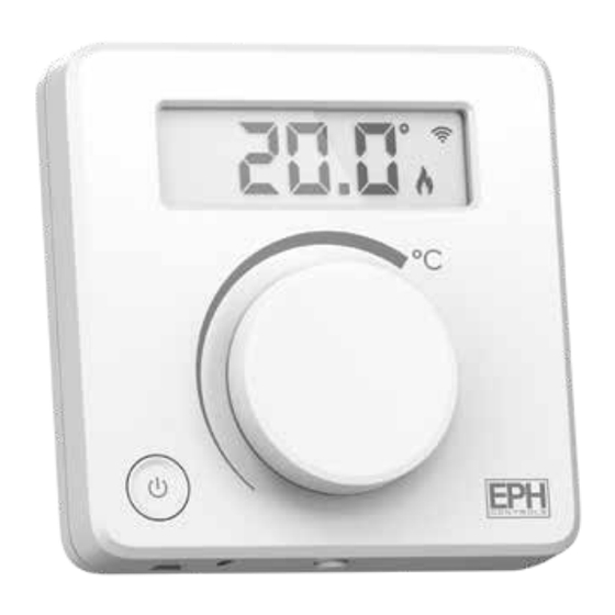
- Page 1 RFRB RF Room Thermostat with On/O Button Installation and Operation Guide...
-
Page 2: Table Of Contents
Table of contents Installation Instructions Factory Default Settings Speci cations How a RFRB Room Thermostat works Mounting & Installation Operating Instructions LCD Symbol Description Button Description Replacing the Batteries Battery Low Warning On/O Function Locking the Keypad Adjusting the Target Temperature To connect a RFRB to a R_7-RF To connect a RFRB... - Page 3 Menu P0 1 Operating Mode Nor (Normal Mode) Delay Start Control (On/O ) Time Proportional Integral Mode (TPI) P0 2 Setting High & Low Limits P0 3 Hysteresis P0 4 Calibration P0 6 Setback P0 7 AFS Air/Floor Sensor P0 8 FHL Floor High Limit P0 9 Resetting the Thermostat...
-
Page 4: Installation Instructions
RFRB Room Thermostat Installation Instructions... -
Page 5: Factory Default Settings
Temperature sensor: NTC 100K Ohm @ 25˚C Temperature indication: ˚C Switching di erential: Adjustable 0.0 … 1.0˚C Note: Good quality batteries are essential to ensure the correct operation of this product. EPH recommend using Duracell or Energiser batteries. EPH Controls Ltd. -
Page 6: How A Rfrb Room Thermostat Works
How a RFRB Room Thermostat works When a RFRB thermostat is calling for heat, it will operate according to the target temperature selected by the user. The target temperature is de ned by turning the dial clockwise for a higher target temperature or anti-clockwise for a lower target temperature. -
Page 7: Mounting & Installation
This thermostat can be mounted in the following ways: 1) To a recessed conduit box 2) To a surface mounted box 3) Directly mounted on a wall 4) Table mounted - Stand Included EPH Controls Ltd. - Page 8 Mounting & Installation Continued 1) The mounting height should be 1.5 metres above the oor level. 2) The thermostat should be located in the room where the heating is to be controlled. The place of installation should be chosen so that the sensor can measure the room temperature as accurately as possible.
- Page 9 Wall mounted Table mounted...
-
Page 10: Operating Instructions
RFRB Room Thermostat Operating Instructions... -
Page 11: Lcd Symbol Description
LCD Symbol Description Room temperature Battery low symbol Wireless symbol Installer Menu Keypad lock symbol Delay Start Setback Limit Heating ON symbol EPH Controls Ltd. -
Page 12: Button Description
Button Description Set point handwheel ON/OFF button Release button RF button KEY3 Reset button RFRB... -
Page 13: Replacing The Batteries
Insert the 2 x AAA batteries and the thermostat will turn on. Close the battery compartment. Battery Low Warning When the batteries are almost empty, the symbol will appear on the screen. The batteries must now be replaced or the unit will shut down. EPH Controls Ltd. -
Page 14: On/O Function
On / O Function Press to turn the thermostat On or O . When OFF is displayed on the screen the thermostat and zone will be set to OFF. Note: If the zone is in the constant OFF mode and the ON/OFF button is pressed, this will change the mode of the zone to constant ON. -
Page 15: To Connect A Rfrb To A R_7-Rf
5. On the R_7-RF Put the next thermostat into pairing mode or press to return to the main screen. Note: When pairing additional zones to an R_7-RF ‘r02’ , ‘r03’, ‘r04’ can appear on the thermostat screen. EPH Controls Ltd. -
Page 16: To Connect A Rfrb To A Ufh10-Rf
To connect a RFRB to a UFH10-RF 1. On the UFH10-RF: , ‘P01 rF COn’ will appear on the screen. Press MENU , ‘RF CONNECT’ will appear solid on the screen. Press Rotate to choose the zone you would like to connect to. Press to con rm. -
Page 17: To Disconnect A Rfrb V2 From Both R_7-Rf
Press and hold the RF button appears on the screen. Press the twice to con rm. The thermostat is now disconnected. Note: The thermostats can also be disconnected at the R_7-RF or UFH10-RF. Please see R_7-RF or UFH10-RF operation guide for details. EPH Controls Ltd. -
Page 18: Menu
Menu This menu allows the user to adjust additional functions. P0 1 Operating Mode (Normal / Delay Start / TPI) There are three settings for selection, Normal, Delay Start or TPI mode. The default setting is Normal. Press and hold the together for 5 seconds, ‘P01’... -
Page 19: Nor (Normal Mode)
When the temperature rises above the target temperature, will disappear, and the thermostat will cancel the demand for heat. Graph (17.1): On / O Control Temp 22˚C Target Temperature 21˚C 20˚C 19˚C 18˚C 17˚C Time Minutes EPH Controls Ltd. -
Page 20: Delay Start Control (On/O )
P0 1 Operating Mode Continued Delay Start Control (On/O ) When the delay start mode is active, ‘DS’ will appear continuously on the screen. When in this mode the thermostat is delayed by a variable time depending on the current temperature, target temperature and also the fall in temperature from when the delay start has activated. - Page 21 3°C the thermostat will delay starting for circa 24 minutes. If the di erence is 6°C or more then the thermostat will be switched on immediately. The time delay will change if the temperature drops from the original calculation. EPH Controls Ltd.
-
Page 22: Time Proportional Integral Mode (Tpi)
P0 1 Operating Mode Continued Time Proportional Integral Mode (TPI) When the thermostat is in TPI mode and the temperature is rising in the zone and falls into the Proportional Bandwith section, TPI will start to a ect the thermostats operation. The thermostat will turn on and o as it gains heat so that it doesn’t overshoot the target by too much. - Page 23 TPI control. You can set this temperature from 1.5°C to 3.0°C in 0.1°C increments. Graph (21.1): TPI Control Temp 22˚C Target Temperature 21˚C 20˚C Proportional Bandwidth 19˚C 18˚C 17˚C Time Minutes Heating On Heating O EPH Controls Ltd.
-
Page 24: P0 2 Setting High & Low Limits
P0 2 Setting High and Low limits Hi 35°C Lo 5°C This function allows the installer to change the minimum and maximum temperatures that the thermostat can operate between. To access this setting press and hold & together for 5 seconds. -
Page 25: P0 3 Hysteresis
‘HOFF’ appears on the screen & the temperature will begin to ash. to select the ‘HOFF’ temperature, press to con rm. The settings will be saved and the user will be returned to the previous screen. Press to return to normal operation. EPH Controls Ltd. -
Page 26: P0 4 Calibration
P0 4 Calibration This function allows the installer to calibrate the temperature of the thermostat. To access this setting press and hold together for 5 seconds. ‘P01’ will appear on the screen. Rotate clockwise until ‘P04 & CAL’ appears on the screen. Press to select. -
Page 27: P0 6 Setback
Setback temperature between 0°...10°C. Press to con rm. The setback temperature will be saved and the user will be returned to the previous screen. When in Setback mode ‘SB’ will appear on the screen. EPH Controls Ltd. -
Page 28: P0 7 Afs Air/Floor Sensor
P0 7 – AFS Air / Floor Sensor 01 Internal air sensor This function allows the user to select between 3 di erent temperature sensor options. 01 Internal air sensor – This option allows the user to record the room temperature using the internal sensor. This is the default option. - Page 29 ‘01’ will ash on the screen. Rotate to choose between options 01, 02 & 03. Press to con rm. Press to return to normal operation. Note: NTC10K temperature sensor can be bought separately as an accessory. EPH Controls Ltd.
-
Page 30: P0 8 Fhl Floor High Limit
P0 8 – FHL Floor High Limit 26°C This function allows the user to select the high limit temperature of the external sensor. Selectable temperature range 5°C – 45°C. Temperature Sensor 03 must be selected, See Page 26 PO7 AFS. To access this setting press and hold the together for 5 seconds. -
Page 31: P0 9 Resetting The Thermostat
The thermostat will restart and revert to its factory de ned settings. Note: The thermostat may also be master reset by using the reset button located on the PCB inside of the thermostat. Press and follow the instructions above. EPH Controls Ltd. - Page 32 EPH Controls IE technical@ephcontrols.com www.ephcontrols.com/contact-us +353 21 471 8440 Cork, T12 W665 EPH Controls UK technical@ephcontrols.co.uk www.ephcontrols.co.uk/contact-us +44 1933 322 072 Harrow, HA1 1BD...
Need help?
Do you have a question about the RFRB V2 and is the answer not in the manual?
Questions and answers