Table of Contents
Advertisement
Quick Links
Advertisement
Table of Contents

Subscribe to Our Youtube Channel
Related Manuals for EPH Controls HDT


Summary of Contents for EPH Controls HDT
- Page 1 Room Thermostat Installation and Operation Guide...
-
Page 2: Table Of Contents
Table of contents Factory default settings Speci cations LCD Display Buttons Wiring Mounting & installation On / O Function & Adjusting the setpoint temperature Locking the Keypad / Backlight Menu Function PO 1 Operating Mode Nor (Normal Mode) Delay Start Control (On/O ) Time Proportional Integral Mode (TPI) - Page 3 PO 2 Setting High and Low limits PO 3 Hysteresis HOn and HO PO 4 Calibration PO 5 Setback Mode PO 6 Frost Protection Resetting the Thermostat...
- Page 4 Mains operated non-programmable Room Thermostat Installation Instructions...
-
Page 5: Factory Default Settings
Factory default settings Contacts: Volt Free High and Low Temp. limitation: Keypad lock: Backlight: Auto Setback: 0.0˚C (o ) Operating mode: Normal EPH Controls Ltd. -
Page 6: Speci Cations
Speci cations Power supply / Input: 230Vac 50-60Hz Power consumption: 7mA / 1 Watt Temperature range: 5 … 35˚C Ambient temperature: 0 … 45˚C Ambient admissible humidity: 5-95%RH Contact rating: 7A 230Vac Dimensions: 85 x 85 x 36mm Temperature sensor: NTC 100K Backlight: White... -
Page 7: Lcd Display
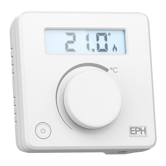
If the keypad is locked, the lock symbol is displayed. When the thermostat is calling for heat, the ame symbol is displayed. When a high or low temperature limit is set, ‘LIM’ is displayed. Displayed when setback is enabled. Displayed when delay start is enabled. EPH Controls Ltd. -
Page 8: Buttons
Buttons Reset Handwheel Button Standby Button... -
Page 9: Wiring
0V on Terminal 1: Thermostat works in Setback mode * If mains output is required terminals L and 2 must be electrically linked. Terminal Connections Live In Neutral In Terminal 1 Setback Terminal 2 Common Terminal 3 EPH Controls Ltd. -
Page 10: Mounting & Installation
Mounting & Installation Caution! Installation and connection should only be carried out by a quali ed person. ƒ Only quali ed electricians or authorised service sta are permitted to open the ƒ thermostat. If the thermostat is used in a way not speci ed by the manufacturer, its safety may be ƒ... - Page 11 Screw the backplate onto a back box or directly to the surface. Wire the thermostat according to the wiring diagram on page 6. Close the front housing and tighten the screw on the bottom of the thermostat. EPH Controls Ltd.
- Page 12 45 113...
- Page 13 Mains operated non-programmable Room Thermostat Operating Instructions...
-
Page 14: On / O Function & Adjusting The Setpoint Temperature
On / O Function Press to turn the thermostat On or O . When in the ON mode the thermostat will display the current ambient temperature. When in the OFF mode the thermostat will display the current ambient temperature and the word ‘OFF’ . Adjusting the setpoint temperature Rotate clockwise to increase the target temperature. -
Page 15: Locking The Keypad / Backlight
The backlight is permanently o . To adjust the backlight setting, press for 10 seconds. ‘bL AUtO’ appears on the screen. Rotate to change the mode between AUTO, ON and OFF. Press to con rm selection and to return to normal operation. EPH Controls Ltd. -
Page 16: Menu Function
Menu Function This menu allows the user to adjust additional functions. PO 1 Operating Mode (Normal / Delay Start / TPI) There are three settings for selection, Normal, Delay Start or TPI mode. The default setting is Normal. Press and hold the together for 5 seconds, P01 &... -
Page 17: Nor (Normal Mode)
When the temperature rises above the setpoint temperature, will disappear, and the thermostat will cancel the demand for heat. Graph (14.1): On / O Control Temp 22˚C Setpoint Temperature 21˚C 20˚C 19˚C 18˚C 17˚C Time Minutes EPH Controls Ltd. -
Page 18: Delay Start Control (On/O )
PO 1 Operating Mode (Normal / Delay Start / TPI) Delay Start Control (On/O ) When the delay start mode is active, ‘dS’ will appear continuously on the screen. When in this mode the thermostat is delayed by a variable time depending on the current temperature, setpoint temperature and also the fall in temperature from when the delay start has activated. - Page 19 24 minutes. If the di erence is 6°C or more then the thermostat will be switched on immediately. The time delay will change if the temperature drops from the original calculation. EPH Controls Ltd.
-
Page 20: Time Proportional Integral Mode (Tpi)
PO 1 Operating Mode (Normal / Delay Start / TPI) Time Proportional Integral Mode (TPI) When the thermostat is in TPI mode and the temperature is rising in the zone and falls into the Proportional Bandwith section, TPI will start to a ect the thermostats operation. - Page 21 TPI control. You can set this temperature from 1.5°C to 3.0°C in 0.1°C increments. Graph (18.1): TPI Control Temp 22˚C 21˚C Setpoint Temperature 20˚C Proportional Bandwidth 19˚C 18˚C 17˚C Time Minutes Heating On Heating O EPH Controls Ltd.
-
Page 22: Po 2 Setting High And Low Limits
PO 2 Setting High and Low limits Hi 35°C Lo 5°C This menu allows the installer to change the minimum and maximum temperatures that the thermostat can be set at. To access this setting press and hold together for 5 seconds. ‘P01 &... -
Page 23: Po 3 Hysteresis Hon And Ho
‘HO ’ appears on the screen and the temperature will begin to ash. to select the ‘HO ’ temperature, press to con rm. Press to con rm. The settings will be saved and the user will be returned to the previous screen. EPH Controls Ltd. -
Page 24: Po 4 Calibration
P04 – Calibration This menu allows the installer to calibrate the temperature of the thermostat. To access this setting press and hold together for 5 seconds. ‘P01 & Nor’ will appear on the screen. Rotate clockwise until ‘P04 & CALI’ appears on the screen. Press to select. -
Page 25: Po 5 Setback Mode
Setback temperature will begin ashing on the screen. Rotate to set the Setback temperature. Press to con rm. The setback temperature will be saved and the user will be returned to the previous screen. When in Setback mode ‘SB’ will appear on the screen. EPH Controls Ltd. -
Page 26: Po 6 Frost Protection
P06 – Frost Protection Frost protection is built into this thermostat, it is pre xed to 5°C and is not adjustable. It will only be activated when the thermostat is in the standby mode and the temperature drops below 5°C. To access the setting, press and hold together for 5 seconds. -
Page 27: Resetting The Thermostat
‘rst’ will appear on the screen and ‘nO’ will ash. Rotate clockwise. ‘rst’ will remain and ‘YES’ will ash on the screen. Press to con rm. The thermostat will restart and revert to its factory de ned settings. EPH Controls Ltd. - Page 28 EPH Controls IE sales@ephcontrols.com www.ephcontrols.com T +353 21 434 6238 F +353 21 454 5890 EPH Controls UK sales@ephcontrols.co.uk www.ephcontrols.co.uk T +44 1933 626 396 F +44 1933 626 218...
Need help?
Do you have a question about the HDT and is the answer not in the manual?
Questions and answers