
Related Manuals for SCIFIT PROII Series


Summary of Contents for SCIFIT PROII Series
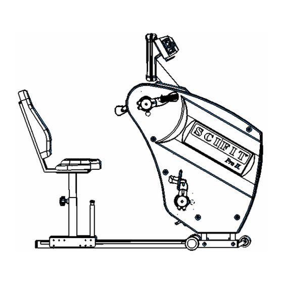
- Page 1 PROII PROII Series All-Body Ergometers Service Manual Customer Service: (800) 745-1373 or (918) 359-2000, ext. 3 service@scifit.com www.scifit.com...
-
Page 2: Table Of Contents
Table of Contents Section Page General Information Theory of Operations III. Mechanical Troubleshooting Electrical Troubleshooting Adjustments and Parts Replacement Assembly Drawings and Part List... -
Page 3: General Information
Technical Support For further assistance in the service of SCIFIT products, please call (800) 745-1373 or (918) 359-2000, ext 3. We can also be reached by fax at (918) 359-2045 or by e-mail at service@scifit.com. The Product Support department is staffed from 7 AM to 6 PM CST Monday through Friday. - Page 4 Heart Rate PCB/ Transmitter Freight and Shipping SCIFIT is NOT responsible for the repair or replacement of any unit or part damaged during transit or installation. Fire, flood, and acts of God are NOT covered under this warranty. The customer is responsible for pursuing all freight damage claims with the appropriate transit company.
- Page 5 Installation SCIFIT is NOT responsible for the repair or replacement of any unit or part damaged during installation. The customer is responsible for inspection of each unit and part for damage at the time of installation. The customer is responsible for pursuing all damage claims with the installer.
- Page 6 NOT be covered under warranty. Preventative maintenance, completed according to the schedule below, will keep your SCIFIT elliptical functioning properly. We realize your time is valuable and have kept these maintenance items to a minimum.
-
Page 7: Theory Of Operations
Theory of Operations The following is a theory of operation that encompasses all the electrical components, their functions, and how they interact with each other. Independent electrical components found in SCIFIT’s Cordless product line: Lower PCB (Power Supply) Upper PCB (Display) - Page 8 Electromagnetic Brake o An eddie current transformer that uses rising and collapsing electromagnetic fields to slow down the generator magnet traveling through it’s field. o Controlled by the lower PCB. 4. 12 Volt DC Battery A. 12 volt sealed lead acid 1.3 Amp Hour Battery. B.
- Page 9 The battery is charged anytime there is more than 13 RPM’s present. Stopping the unit When pedaling is discontinued, the brake continues to spin. The battery will engage once the actual RPM’s dip below 13. The battery remains active for 15 seconds and then a transistor that connects the battery to the rest of the lower PCB is unlatched.
-
Page 10: Mechanical Troubleshooting
III. Mechanical Troubleshooting A. Mechanical Troubleshooting Table Problem Possible Reasons Solutions Handle shaft is loose or Tighten or replace handle Hand cranks wobble when cranks are stripped. shaft, if threads are damaged. rotated. Arm crank threads are Replace arm crank. stripped. - Page 11 Mechanical Troubleshooting Table (cont.) Problem Possible Reasons Solutions Hand crank or foot Cotter pin through the inner Tighten or replace cotter pin. crank assembly has hub is not tight enough. side-to-side play. Snap ring is not in snap ring Install snap ring back into groove on axle.
- Page 12 Mechanical Troubleshooting Table (cont.) Problem Possible Reasons Solutions Clunking noise from User is over-speeding brake Increase the work load or inside the unit when and brake drive pulley decrease rpms. because work load too low. cranks are being rotated. Brake pulley is loose. Fix pulley or replace brake assembly.
-
Page 13: Iv. Electrical Troubleshooting
IV. Electrical Troubleshooting Electrical Troubleshooting Table Problem Possible Reason Solution No lights are showing on the Unit is not in use. Start rotating cranks (at least upper PCB at idle. 13 RPMs). Unit stays lit for 15 seconds after use unless a wall pack is in use. - Page 14 Faulty lower PCB. Replace lower PCB. Faulty upper PCB. Replace upper PCB. Resistance is different than Defined unit type has been Redefine unit type. Call SCIFIT when you received unit. changed. for procedure. Faulty lower PCB. Replace lower PCB. No resistance.
- Page 15 Electrical Troubleshooting Table (cont.) Problem Possible Reason Solution No heart rate displayed. No chest strap worn. Must wear chest strap. Faulty chest strap. Verify chest strap works. Wireless heart rate PCB is not Check and fix connection on plugged in. back of upper PCB.
- Page 16 Troubleshooting Flowcharts Although it is impossible to foresee every eventuality, the flowcharts on the following pages will cover the most common possibilities. If further assistance is required, please consult SCIFIT SYSTEMS, Inc. Query Action Status No Lights On Display When Pedaling Brake is shorted to the chassis.
- Page 17 Query Action Status Resistance Refer To "No Lights On Lights on display Display when Pedaling" while exercising? Flowchart Is three (3) pin When in a cable connection Secure program, does display from JP1 to brake report RPM's? secure? Clear EEPROM. If Ineffective, replace lower PCB.
- Page 18 User Setup (Use this procedure for PROII’s thru serial number 650- 005503.) User Setup provides club owners and managers with certain information about their equipment and enables them to customize certain features. Provide power to the console by either plugging the wall pack into the machine and outlet or working out at a low level on the machine.
- Page 19 previous screens is to enter the User Setup again and move through all the parameters. Pressing ENTER for any message that is empty or invalid will tell the system that message number is the ending message and the scrolling will stop with the previously set message. Pressing ENTER on the 25 screen, the program will advance to the next parameter (Hour Meter) since that is the end of the available memory.
- Page 20 5. Message: If a message has not been entered or is invalid, the upper display will show “NO MESSAGE”. The TIME window will display the message screen number. The screen number range is ct1 through ct25. Each message screen has 10 characters so the total message can have up to 250 characters.
-
Page 21: Adjustments And Parts Replacement
Adjustments and Parts Replacement Upper (Display) PCB Replacement (Use this procedure for PROII’s thru 650-005503.) 1. Using a Philips screwdriver, remove the four (4) display mounting screws on the back of the display mounting plate. 2. Disconnect all cables running to the upper PCB (P1558) and remove the upper console assembly from the unit. - Page 22 5. Install the new upper PCB and replace standoffs. If your unit had two (2) plastic standoffs, these need to be placed back at the bottom of the new upper PCB. 6. Plug the wireless heart rate receiver back into the upper PCB. It plugs into the centermost, 3-pin Molex header.
- Page 23 Upper (Display) PCB Replacement (Use this procedure for PROII’s with serial numbers 650-005504 thru 650-005636.) 1. Using a Philips screwdriver, remove the four (4) display mounting screws on the back of the display mounting plate. 2. Disconnect all cables running to the upper PCB and remove the upper console assembly from the unit.
- Page 24 • Plug the wireless heart rate PCB back into the upper PCB. It plugs into the bottom 3-pin header on the right side of the upper PCB (as shown above). • The ribbon cable plugs into the bottom ribbon cable header on the right side of the upper PCB.
- Page 25 Upper (Display) PCB Replacement (Use this procedure for PROII’s with serial numbers 650-005637 and above.)
- Page 26 1. Remove the five (5) console screws in the console back (P2304), using a Philips screwdriver. 2. Disconnect all cables running to the display PCB (P2160) and remove console face (P2303) from the unit. Make sure the cables do not fall into the neck of the unit.
- Page 27 10. Verify operations of the unit by using different programs. Lower PCB Replacement (Use this procedure for PROII’s with serial numbers thru 650-005503.) 1. Remove crank retaining bolts and washers, using a 5/32” Allen wrench. 2. On the lower right side crank hub assembly (A1871), pull the black knob on the popper pin assembly (A1754) out and slide the crank assembly (A1868) out.
- Page 28 6. Locate the lower PCB (P1559). 7. Disconnect all cables to the lower PCB. Make sure you are grounded when handling electronics. Do not touch any components on the lower PCB. Static damage can occur. 8. Remove the four (4) screws mounting the lower PCB, using a Philips screwdriver.
- Page 29 Lower PCB Replacement (Use this procedure for PROII’s with serial numbers 650-005504 and above.) 1. Remove crank retaining bolts and washers, using a 5/32” Allen wrench. 2. On the lower right side crank hub assembly (A1871), pull the black knob on the popper pin assembly (A1754) out and slide the crank assembly (A1868) out.
- Page 30 5. Remove the six (6) cover screws and washers holding the right side cover in place, using a Philips screwdriver. 6. Locate the lower PCB (P2161). 7. Disconnect all cables to the lower PCB. Make sure you are grounded when handling electronics. Do not touch any components on the lower PCB.
- Page 31 Battery Replacement 1. Remove crank retaining bolts and washers, using a 5/32” Allen wrench. 2. On the lower right side crank hub assembly (A1871), pull the black knob on the popper pin assembly (A1754) out and slide the crank assembly (A1868) out.
- Page 32 6. Locate the battery. 7. Disconnect the two (2) wires connected to the battery. The red wire is connected to the positive terminal while the black wire is connected to the negative terminal. 8. Remove the three (3) Philips screws through the battery mounting bracket (A1570).
- Page 33 Wireless HR Replacement (Use this procedure for PROII’s with serial numbers through 650-005XXX.) Wireless HR Replacement (Use this procedure for PROII’s with serial numbers 650-005XXX thru 650-005XXX.) Wireless HR Replacement (Use this procedure for PROII’s with serial numbers 650-005XXX and above.) Brake Replacement (Right Side View)
- Page 34 (Left Side View) 1. Remove the crank arms and both side covers, using the Crank Arm and Cover Removal procedure. 2. Remove the two (2) nuts holding the tensioning bolt to the tensioning bracket. 3. Remove tensioning bolt from the frame. 4.
- Page 35 16. While still supporting the brake assembly, insert the brake spacer on the left side and start the two (2) brake mounting bolts. Each brake mounting bolt should have a flat washer followed by a lock washer. Tighten bolts finger tight. 17.
- Page 36 Adjustable Crank Locking Pin Removal / Replacement To Remove Locking Pin 1. Remove crank retaining bolts and washers, using a 5/32” Allen wrench. 2. On the upper crank hub (A1884 or A1885), pull the black knob on the locking pin assembly (A1754) out and slide the crank assembly (A1869 or A1870) out.
- Page 37 To Install Locking Pin 1. Make sure threads in the upper or lower crank hub are clean and free of debris. 2. Place a small amount of green loc-tite on the threads of the locking pin assembly. Note: Do not get loc-tite on any area except the threads. This will cause the locking pin to bind up later.
- Page 38 Adjustable Crank Removal and Replacement To Remove Cranks: 1. Remove crank retaining bolts and washers, using a 5/32” Allen wrench. 2. On the upper crank hub (A1884 or A1885), pull the black knob on the locking pin assembly (A1754) out and slide the crank assembly (A1869 or A1870) out.
- Page 39 3. Install foot crank assemblies (A1867 and A1868). With the arm in the down position, the foot crank assembly on that same side must be inserted into the holes in the hub from the side opposite the user. 4. Verify locking pin assemblies are seating properly before using the unit. Note: It is optional whether to reinstall the crank retaining bolts and washers.
- Page 40 End Cap Replacement / Adjustment 1. Position an object under the frame leg to elevate the end cap (A1890). 2. Pull the rubber end cap off the end of the frame leg. For older versions with plastic end caps, a plastic or rubber mallet may be needed to tap on the inner lip of the end cap until it comes off the frame leg.
Need help?
Do you have a question about the PROII Series and is the answer not in the manual?
Questions and answers