SCIFIT Pro1000 Service Manual
Hide thumbs
Also See for Pro1000:
- Owner's manual (28 pages) ,
- User manual (20 pages) ,
- Owner's operation manual (48 pages)
Advertisement
Table of Contents
- 1 Table of Contents
- 2 Overview
- 3 Troubleshooting Tables
-
4
Maintenance Procedures
- 4.1 Board
- 4.2 Procedure 2 - Checking Voltage at the Power Supply Board
- 4.3 Procedure 3 - Checking and Adjusting the Speed Sensor
- 4.4 Procedure 4 - Removal and Replacement of the Brake Assembly
- 4.5 Procedure 5 - Tightening the Poly-V Belt
- 4.6 Procedure 6 - Checking and Adjusting the Tension in the Chains
- 4.7 Figures
- 4.8 Fuse Holder
- 5 Pro1000 Parts List
- Download this manual
Advertisement
Table of Contents

Related Manuals for SCIFIT Pro1000


Summary of Contents for SCIFIT Pro1000
- Page 1 Pro1000 Service Manual SALES: 800-278-3933 CUSTOMER SERVICE: 800-745-1373 Revision: August 1999...
-
Page 2: Table Of Contents
Procedure 6 – Checking and Adjusting the Tension in the Chains Figures Figure 1 – Pro1000 Total Assembly (1-53) Figure 2 – Pro1000 Main Frame (54-99) Figure 3 – Pro1000 Optional Parts (100-112) Figure 4 – Power Entry Module with Fuse Holder Figure 5 –... -
Page 3: Overview
I. Overview Purpose. This manual is designed to assist in service of SCIFIT Pro1000 exercise machines. The manual is divided into sections to diagnose and isolate problems. Troubleshooting tables and procedures, along with drawings, are provided to aid technicians in servicing equipment. The Item Numbers given in the parts list in Section V can be used to determine the location of various parts in Figures 1-4. -
Page 4: Troubleshooting Tables
II. Troubleshooting Tables Table 1 – Electrical Troubleshooting Problem Possible Reasons Solutions 1.1 The machine appears to Faulty power supply If buttons on the control display be off when plugged in beep when pressed, replace power board (Item 87). and switched “on”. supply board. - Page 5 1.7 The upper display (Item Ribbon cable connection Check cable connection at power 2) resets after starting a is loose (Item 6). supply and display boards (Items 87 program. and 2, respectively). Power cord is loose. Check and adjust as needed. Display board is faulty.
- Page 6 Table 2 – Mechanical Troubleshooting Problem Possible Reasons Solutions 2.1 Poly-V belt (Item 69) is Belt tension is not See Procedure 5. slipping. adjusted properly. 2.2 Excessive free play The chain(s) is too loose. See Procedure 6. exists when the cranks are turned.
- Page 7 2.7 No resistance on No speed signal Check and adjust the speed sensor handles and pedals (Item 74) as needed. See when in a program. Procedure 3. Wires going to brake Check that brake wires are properly (Item 68) are discon- connected.
-
Page 8: Maintenance Procedures
Board a. Plug into power source and 1. Unplug the unit from the power turn on. source. b. The message “SCIFIT FOR 2. Remove the crank bars and SCIENTIFIC SOLUTIONS” crank hub assemblies (Items 7 or should be scrolling across 105) from the unit. -
Page 9: Procedure 3 - Checking And Adjusting The Speed Sensor
Refer to Fig. 5. The machine and set aside to return voltmeter should read 4-5 VDC. to SCIFIT (request a UPS call tag 9. If there is no voltage, replace the by phone). power supply board (Item 87);... -
Page 10: Procedure 5 - Tightening The Poly-V Belt
The 5. Check that job is complete by display will be scrolling the rotating crank handles. If there is message, “SCIFIT…” Slowly no noise due to belt slippage, the rotate the crank arm assembly job is complete. If noise persists, and the message will change to a return to step 1. -
Page 11: Procedure 6 - Checking And Adjusting The Tension In The Chains
Procedure 6 – Checking and Adjusting the Tension in the Chains 1. Check the deflection in the two chains along their longest spans. The two chains should never have less than ¼” nor more than 1” deflection at their longest spans. -
Page 12: Figures
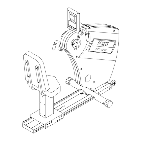
IV. Figures Figure 1 – Pro1000 Total Assembly (Items 1-53) - Page 13 Figure 2 – Pro1000 Main Frame (Items 54-99)
- Page 14 Figure 3 – Pro1000 Optional Parts (Items 100-112)
-
Page 15: Fuse Holder
Figure 4 – Power Entry Module with Fuse Holder... - Page 16 Figure 5 – Pro1000 Wiring Diagram...
-
Page 17: Pro1000 Parts List
31 roller, urethane, 1 1/4 dia. X 3/8 P1038 32 nuts, lock, 5/16 -18 pltd. 33 screw, 10-32x.5, black, b.h., socket cap P1062 34 rod, lock, pos., seat, PRO1000 A1121 35 pin, clevis, 1/4x1" 36 brkt., pos., adj., lever A1115... - Page 18 44 lockwasher, 1/4, pltd. P1056 45 bolt, 1/4-20x1.25, pltd. 46 bracket, spring A1120 47 sticker, track adjustment 48 track, adjustment, seat, stainless steel, Pro1000 A1114 49 decal, manufacturing date 50 endcap, 3"dia 70330 51 screw, M5x1.0x25, s.h., blk. 52 manual, operator's 53 cord, power, 110V, 9'10"...
- Page 19 79 nut, M4x.7, pltd. 80 p.e.m., recep for daisychain 65177 81 module, power entry, RF/EFI 65178 82 screw, 3/16-32x3/8, p.h. 83 cover, supply, power A1043 84 starwasher, #6 85 screw, 6-32x3/8, p.h. 86 standoffs, 3", 6-32 87 power supply, (lower), serial 65150S 88 clip, u-type 89 shell, bearing, crank hub...
Need help?
Do you have a question about the Pro1000 and is the answer not in the manual?
Questions and answers
How to connect the long chain on my bike