Advertisement
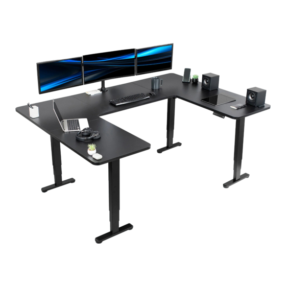
U-Shaped 83" x 60" Dual Motor Electric Desk
SKUS: DESK-E4UBB
Instruction Manual
ASSEMBLY VIDEO AVAILABLE:
Follow along step-by-step with our video walk through by scanning
the QR code with your mobile device or by following the product
link: vivo-us.com/products/desk-e4ubb
help@vivo-us.com
www.vivo-us.com
309-278-5303
Advertisement
Table of Contents

Subscribe to Our Youtube Channel
Related Manuals for Vivo DESK-E4UBB


Summary of Contents for Vivo DESK-E4UBB
- Page 1 U-Shaped 83” x 60” Dual Motor Electric Desk SKUS: DESK-E4UBB Instruction Manual ASSEMBLY VIDEO AVAILABLE: Follow along step-by-step with our video walk through by scanning the QR code with your mobile device or by following the product link: vivo-us.com/products/desk-e4ubb www.vivo-us.com help@vivo-us.com...
- Page 2 7AM - 7PM Monday-Friday Give us a Call: Chat Us: Email Us: 309-278-5303 www.vivo-us.com help@vivo-us.com We’re Here for You! Our customer-minded support team is here for YOU, Monday-Friday 7am-7pm CST. We offer immediate assistance with rapid response times from customer service agents and product techncians to...
-
Page 3: Electrical Warning
Returns | Product Didn’t Work Out? We offer a hassle-free 30 day return on all products. Contact customer support at 309-278-5303 or help@vivo-us.com. Please note: For items ordered in error or no longer needed, the return shipping charges will be at the buyer’s expense. - Page 4 PACKAGE CONTENTS Please consult the parts list below and ensure you have everything you need to assemble your product. If parts are missing or damaged, please contact us. 1 (x1) 2 (x1) 4 (x1) 3 (x1) Right Extension Right Corner Left Corner Middle Desktop 5 (x1)
- Page 5 HARDWARE S-A (x30) S-B (x18) S-C (x74) S-D (x5) S-E (x14) M6x11mm M6x35mm M5x15mm M8x12mm Wooden Screw Screw Screw Screw Dowels T-A (x1) T-B (x1) 5mm Allen 2mm Allen Wrench Wrench TOOLS NEEDED: Phillips Screwdriver Level...
- Page 6 ASSEMBLY STEPS STEP 1.1 Forming Leg Assembly A Attach Short Right Crossbar (12) to Motorized Leg A (6) with M6x11mm Screws (S-A) using 5mm Allen Wrench (T-A). 6 (x1) 12 (x1) S-A (x2) 5mm Allen Motorized Short Right M6x11mm Wrench Leg A Crossbar Screw...
- Page 7 STEP 1.2 Connect Side Brackets Attach Side Bracket (11) to Motorized Leg A (6) with M8x12mm Screws (S-D) using 5mm Allen Wrench (T-A). 11 (x1) S-D (x2) 5mm Allen Side Bracket M8x12mm Wrench Screw...
- Page 8 STEP 1.3 Attach Foot Connect Foot (10) to underside of Motorized Leg A (6) with M6x35mm Screws (S-B) using 5mm Allen Wrench (T-A). 10 (x1) S-B (x4) Foot M6x35mm 5mm Allen Screw Wrench...
- Page 9 STEP 2.1 Forming Leg Assembly B Attach Short Right Crossbar (12) to Leg A (8) with M6x11mm Screws (S-A) using 5mm Allen Wrench (T-A). 8 (x1) 12 (x1) S-A (x2) 5mm Allen Leg A Short Right M6x11mm Wrench Crossbar Screw...
- Page 10 STEP 2.2 Attach Crossbar Attach Long Left Crossbar (15) to Leg A (8) with M6x11mm Screws (S-A) using 5mm Allen Wrench (T-A). 15 (x1) S-A (x2) 5mm Allen Long Left M6x11mm Screws Wrench Crossbar...
- Page 11 STEP 2.3 Attaching Foot Connect Foot (10) to the underside of Leg A (8) with M6x35mm Screws (S-B) using 5mm Allen Wrench (T-A). 10 (x1) S-B (x4) 5mm Allen Foot M6x35mm Screws Wrench...
- Page 12 STEP 3.1: Forming Leg Assembly C Attach Short Left Crossbar (14) to Leg B (9) with M6x11mm Screws (S-A) using 5mm Allen Wrench (T-A). 9 (x1) 14 (x1) S-A (x2) 5mm Allen Leg B Show Left M6x11mm Wrench Crossbar Screws...
- Page 13 STEP 3.2 Attaching Side Bracket Connect Side Bracket (11) to Leg B (9) with M8x12mm Screws (S-D) using 5mm Allen Key (T-A). S-D (x2) 11 (x1) 5mm Allen M8x12mm Side Bracket Wrench Screws...
- Page 14 STEP 3.3 Attach Foot Connect Feet (10) to the underside of Leg B (9) with M6x35mm Screws (S-B) using 5mm Allen Wrench (T-A). S-B (x4) 10 (x1) 5mm Allen M6x35mm Screws Foot Wrench...
- Page 15 STEP 4.1: Forming Leg Assembly D Attach Short Left Crossbar (14) to Motorized Leg B (7) with M6x11mm Screws (S-A) using 5mm Allen Wrench (T-A). 7 (x1) 14 (x1) S-A (x2) 5mm Allen Wrench Motorized Leg B Short Left Crossbar M6x11mm Screws...
- Page 16 STEP 4.2 Secure Crossbar Attach Long Right Crossbar (13) to Motorized Leg B (7) with M6x11mm Screws (S-A) using 5mm Allen Wrench (T-A). 13 (x1) S-A (x2) Long Right M6x11mm Screws 5mm Allen Wrench Crossbar...
- Page 17 STEP 4.3 Attach Foot Connect Foot (10) to underside of Motorized Leg B (7) with M6x35mm Screws (S-B) using 5mm Allen Wrench (T-A). 10 (x1) S-B (x4) Foot M6x35mm Screws 5mm Allen Wrench...
- Page 18 STEP 5 Combining Leg Assemblies Connect the Leg Assembly A to Leg Assembly B, and Leg Assembly C to Leg Assembly D with Connector Brackets (18) using M6x11mm Screws (S-A) and 5mm Allen Wrench (T-A). 18 (x2) S-A (x8) Long Connector Bracket M6x11mm Screw 5mm Allen Wrench...
- Page 19 STEP 5 Continued Connect both combined assmeblies together with Short Connector Brackets (19) and Middle Crossbar (16) using M6x11mm Screws (S-A) and 5mm Allen Wrench (T-A). S-A (x8) 16 (x1) 19 (x2) M6x11mm Screw Middle Crossbar 5mm Allen Wrench Short Connector Bracket...
- Page 20 STEP 6 Level Legs Flip the frame right side up using help from a second person. Ensure all of the legs are level by measuring from the top of the feet to the bottom of the upper stage on the legs. If both legs are level, proceed to STEP 7 on page 22.
- Page 21 STEP 6 Level Legs - Cont’d ** FOLLOW STEPS BELOW TO LEVEL LEGS ** Insert the Sync Rod (17) into the non-motorized leg (8 or 9) that is uneven. Turn the rod to adjust the leg height until it is level with the motorized leg (6 or 7). Turn the sync rod counterclockwise to raise the leg and clockwise to lower it.
- Page 22 STEP 7 Connect Sync Rod 1. Loosen the nut on Sync Rod (17). 2. Insert the hex end of Sync Rod into Leg A (8). 17 (x2) Sync Rod 2mm Allen Wrench...
- Page 23 STEP 7 Connect Sync Rod - Cont’d 3. While holding the hex end, pull the larger rod out until the connector engages with Motorized Leg A (6). 4. Tighten the set screw on Sync Rod (17) using 2mm Allen Wrench (T-B), then tighten the nut.
- Page 24 STEP 8 Installing Anti-Vibration Pads Press Anti-Vibration Pads (25) into tabs on crossbars, supports, and side bracket tabs, as shown below. 25 (x34) Anti-Vibration Pads...
-
Page 25: Right Corner
STEP 9 Lay Out Desktops Align all five Desktops (1 thru 5) laying on a clean flat surface with the pilot holes facing up, and arrange using diagram below: Right Corner Middle Desktop Left Corner PLEASE NOTE: Pilot holes on Middle Desktop should mirror holes on Left &... - Page 26 STEP 10 Assemble Desktop Secure Desktops (1-5) using three Wooden Dowels (S-E) in between each desktop. Secure together using two Connector Plates (27) for each piece, overlapping the seams, M5x15mm Screws (S-C) and a Phillips screwdriver. 27 (x8) S-C (x32) S-E (x12) Connector M5x15mm...
- Page 27 STEP 11 Place Desktop on Frame With the aide of two or more people, flip the assembled desk frame upside down and place onto the assembled desktop. Begin aligning the frame pilot holes with the desktop holes. TEAM LIFT: It is recommended to lift and place desk frame onto desktop with the aide of 2 or 3 people.
- Page 28 STEP 12 Secure Desktops Secure each desktop panel to assembled desk frame using M5x15mm Screws (S-C) and a Phillips screwdriver. S-C (x34) M5x15mm Screw...
- Page 29 STEP 13 Connect Control Panel & AC Adapter Connect Control Panel (20) to desktop using M5x15mm Screws (S-C) and a Phillips screwdriver. Place Adapter Bracket (28) over AC Adapter (22) and secure to desktop using M5x15mm Screws (S-C) and a Phillips screwdriver. Note: Controller can be installed on either side of desk using provided pre- drilled holes.
- Page 30 STEP 14 Attach Power Cords Connect cables from the Motorized Legs (6, 7) to slots marked M1 & M2 on Controller (20), using Extension Cables (21) to connect furtherest motor cable. Connect cord from AC Adapter (22) to Controller (20) and then connect Power Cord (23) to AC Adapter (22). Plug end of Power Cord into a wall outlet to power desk.
- Page 31 STEP 15 Installing Hooks With the aide of two or more people, flip the assembled desk right side up. Install Hooks (26) by squeezing at the top and sliding them into the slots in Side Brackets (11). TEAM LIFT: It is recommended to lift assembled dek with the aide of 2 or 3 people.
- Page 32 CONTROLLER - USER MANUAL Arrow Keys Press and hold the UP arrow for the desk to begin raising. Release when desk reaches desired height. Press and hold DOWN arrow to lower desk. Release button when desired height is reached. Memory Presets Save your preffered heights.
-
Page 33: Troubleshooting
Reset Mode Press and hold the down arrow. “RES” will be displayed and the leg will lower and rebound upwards. Release the down arrow and your frame has been reset. Change Display Height Unit To change the display unit of height from metric to imperial, press and hold the “S” button until a flashing “S-”... - Page 34 WHO WE ARE VIVO is more than a brand of ergonomic office furniture. We are a team of creative and innovative indivuduals working together to offer high quality, affordable ergonomic solutions. We think and work outside of the box to serve...
-
Page 35: Need Assistance
Call Us: 309-278-5303 Average Resolution Time: 5m 4s Chat Us: www.vivo-us.com Average Resolution Time: < 15m Email Us: help@vivo-us.com Average Resolution Time: 1HR 8M 23% within < 15m 38% within <... - Page 36 LOVE YOUR NEW VIVO SETUP? Ready to share that new amazing setup? Want to brag about that amazing new ergonomic solution? Tag us in your photo! VIVO-us @vivo_us FOR MORE GREAT VIVO PRODUCTS, CHECK OUT OUR WEBSITE AT: WWW.VIVO-US.COM LAST UPDATED: 01/02/2024 REV1LF...
Need help?
Do you have a question about the DESK-E4UBB and is the answer not in the manual?
Questions and answers