Advertisement
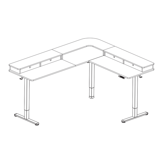
Black 2 Tier 75" x 63" Corner Table Top with Storage
Instruction Manual
SKU: DESK-E3CVB-75 SERIES
Frame:
Table Top:
DESK-E375B
DESK-E3CVB-75-A
ASSEMBLY VIDEO AVAILABLE:
Follow along step-by-step with our video walk through by scanning
the QR code with your mobile device or by following the product
link: vivo-us.com/products/desk-e3cvb
help@vivo-us.com
www.vivo-us.com
309-278-5303
Advertisement
Table of Contents

Related Manuals for Vivo DESK-E3CVB-75 Series


Summary of Contents for Vivo DESK-E3CVB-75 Series
- Page 1 Black 2 Tier 75” x 63” Corner Table Top with Storage Instruction Manual SKU: DESK-E3CVB-75 SERIES Frame: Table Top: DESK-E375B DESK-E3CVB-75-A ASSEMBLY VIDEO AVAILABLE: Follow along step-by-step with our video walk through by scanning the QR code with your mobile device or by following the product link: vivo-us.com/products/desk-e3cvb...
- Page 2 7AM - 7PM Monday-Friday Give us a Call: Chat Us: Email Us: 309-278-5303 www.vivo-us.com help@vivo-us.com We’re Here for You! Our customer-minded support team is here for YOU, Monday-Friday 7am-7pm CST. We offer immediate assistance with rapid response times from customer service agents and product techncians to...
- Page 3 Returns | Product Didn’t Work Out? We offer a hassle-free 30 day return on all products. Contact customer support at 309-278-5303 or help@vivo-us.com. Please note: For items ordered in error or no longer needed, the return shipping charges will be at the buyer’s expense.
-
Page 4: Package Contents
Package Contents Desktop & Shelf Parts A1 (x1) A2 (x1) A3 (x1) B1 (x1) B2(x1) Corner Panel Right Panel Left Panel Corner Shelf Panel Left Shelf Panel B3 (x1) B4 (x8) B5 (x1) B6 (x1) B7 (x2) Right Shelf Panel Shelf Divider Short Corner Long Corner... -
Page 5: Included Hardware & Tools
Misc Parts Q (x2) S (x1) T (x1) U (x1) V (x21) Connector Plate Control Panel AC Adapter Extension Cable Anti-Vibration Pads Y (x2) W (x6) X (x5) Hook Cable Clip Locking Caster Included Hardware & Tools S-E (x20) S-A (x18) S-B (x9) S-C (x47) S-D (x26) -
Page 6: Assembly Steps
ASSEMBLY STEPS STEP 1: Assemble Left Leg Attach Straight Outer Crossbar (D) to Left Leg (M) using M6x8mm Screws (S-A) and 5mm Allen Wrench (T-A). Attach Side Bracket (J) to Left Leg (M) using M6x8mm Screws (S-A) and 5mm Allen Wrench (T-A). - Page 7 STEP 2: Assemble Right Leg Attach Angled Outer Crossbar (G) to Right Leg (L) using M6x8mm Screws (S-A) and 5mm Allen Wrench (T-A). Attach Side Bracket (J) to Right Leg (L) using M6x8mm Screws (S-A) and 5mm Allen Wrench (T-A).
- Page 8 STEP 3: Install Feet & Connect Motorized Leg Attach Feet (R) to Left and Right Legs (M,L) using M6x35mm Screw (S-B) and 5mm Allen Wrench (T-A). Optional: Add Casters The preinstalled foot pads can be removed and replaced with Locking Casters (X). Tighten the Locking Casters using Wrench (T-C).
- Page 9 STEP 3.1: Install Feet & Connect Motorized Leg Connect Short Corner Crossbar (E) and Long Corner Crossbar (F) to Motorized Leg (K) using M6x8mm Screws (S-A) and 5mm Allen Wrench (T-A). Please Note: All legs need to use the same foot style for proper leveling.
- Page 10 STEP 4: Install Anti-Vibration Pads Affix Anti-Vibration Pads (V) to the desk frame and Connector Bracket (N).
- Page 11 STEP 5: Assemble Desktop Lay the Desktop Panels (A1, A2, A3) on a protective surface, following the pattern below, with the pilot holes facing up. Join the Corner Panel (A1) and Right Panel (A2) using Connector Plate (Q) and ST5x15mm Screws (S-C).
- Page 12 STEP 6: Install Connector Brackets Place the Leg assemblies on the desktop as shown with the mounting holes aligned with the pilot holes on the desktop. Attach the Crossbar Connector Bracket (N) to the Angled Outer Crossbar (G) and Long Corner Crossbar (F) using M6x8mm Screws (S-A) and 5mm Allen Wrench (T-B). Slide Inner Crossbar (O) into Short Corner Crossbar (E) making sure the slotted section is facing towards the motor.
- Page 13 STEP 7: Secure Frame & Desktop Secure the frame assembly, Hooks (Y), and Control Panel (S) to the desktop using ST5x15mm Screws (S-C) and a Phillips screwdriver or Power Drill.
- Page 14 STEP 8: Install Sync Rod Insert the hex shaft end on Long and Short Sync Rods (H, I) into Right and Left Legs (L, M) making sure the metal retaining ring makes contact with the leg. Ensure all three legs are at the same height. If they are not, turn the sync rod clockwise to lower the legs (fig.1), and counterclockwise to raise the legs (fig.
- Page 15 Cont’d Coupling Nut...
- Page 16 STEP 8.2 Tighten coupling nuts, then tighten both set screws on the end of Sync Rods using 2mm Allen Wrench (T-B).
- Page 17 STEP 9: Connect Power Cords Connect AC Adapter (T) and the cable from Motorized Leg (K) to the back of Control Panel (S). If needed, use the Extension Cable (U) to extend the cable coming off of Motorized Leg (K). Remove the protective film on Cable Clips (W) and attach them to the desktop to help organize cables.
- Page 18 STEP 10: Assemble Shelf Dividers Assemble Shelf Dividers (B4), Short Corner Shelf Panel (B5), Long Corner Shelf Panel (9B6, and Rear Shelf Panels (B7) to the desktop assembly using ST4.2x35mm Screws (S-D) and a Phillips screwdriver using all locations shown below.
- Page 19 STEP 11: Connect Shelf Assembly Insert Cam Lock Screws (S-E) using a Phillips screwdriver and Wooden Dowels (S-H) into Corner Shelf Panel (B1), Left Shelf Panel (B2), and Right Shelf Panel (B3). Place the Shelf Assembly on top of the divider assembly.
- Page 20 STEP 12: Secure Shelf Insert Cam Lock Nuts (S-F) into Panels, making sure arrows are facing up. Using a Phillips screwdriver, turn Cam Lock Nuts (S-F) clockwise to secure the shelf assembly in place.
- Page 21 STEP 13: Unfold Drawers Unfold Drawers (C) and place the drawer inserts inside.
- Page 22 STEP 13.2 Slide drawers into shelf assembly.
- Page 23 CONTROLLER - USER MANUAL Memory Presets Press any number and the desk will return to the programmed height. See Programing Memory Presets to program presets. Arrow Keys Press and hold the UP arrow for the desk to begin raising. Release when desk reaches desired height.
- Page 24 WHO WE ARE VIVO is more than a brand of ergonomic office furniture. We are a team of creative and innovative indivuduals working together to offer high quality, affordable ergonomic solutions. We think and work outside of the box to serve...
-
Page 25: Need Assistance
Call Us: 309-278-5303 Average Resolution Time: 5m 4s Chat Us: www.vivo-us.com Average Resolution Time: < 15m Email Us: help@vivo-us.com Average Resolution Time: 1HR 8M 23% within < 15m 38% within <... - Page 26 [ THIS PAGE INTENTIONALLY LEFT BLANK ]...
- Page 27 [ THIS PAGE INTENTIONALLY LEFT BLANK ]...
- Page 28 LOVE YOUR NEW VIVO SETUP? Ready to share that new amazing setup? Want to brag about that amazing new ergonomic solution? Tag us in your photo! VIVO-us @vivo_us FOR MORE GREAT VIVO PRODUCTS, CHECK OUT OUR WEBSITE AT: WWW.VIVO-US.COM LAST UPDATED: 01/11/2024 REV1LF...
Need help?
Do you have a question about the DESK-E3CVB-75 Series and is the answer not in the manual?
Questions and answers