Table of Contents
Advertisement
Quick Links
Advertisement
Table of Contents

Related Manuals for St. Jude Medical Brio 6788


Summary of Contents for St. Jude Medical Brio 6788
- Page 1 Brio ™ Deep Brain Stimulation System Clinician’s Manual...
- Page 2 Unless otherwise noted, ™ indicates that the name is a trademark of, or licensed to, St. Jude Medical or one of its subsidiaries. ST. JUDE MEDICAL and the nine-squares symbol are trademarks and service marks of St. Jude Medical, LLC and its related companies.
-
Page 3: Table Of Contents
C O N T E N T S About This Manual . . . . . . . . . . . . . . . . . . . . . . . . . . . . . . . . . . . . . . . . . . . . . . . . . . . . . . . . . . . . . . . . . . Brief System Description . - Page 4 Check Impedance . . . . . . . . . . . . . . . . . . . . . . . . . . . . . . . . . . . . . . . . . . . . . . . . . . . . . . . . . . . . . . . . . . . . . . . . . . . Set AMP Limits .
-
Page 5: About This Manual
A B O U T T H I S M A N U A L This manual provides information about the St. Jude Medical™ Brio™ clinician programmer (Model 6851) and Brio™ implantable pulse generator (IPG, Model 6788). For information about other components of the Brio™... -
Page 6: Symbols And Definitions
S Y M B O L S A N D D E F I N I T I O N S The following symbols may be used in this document and on some of the products and packaging: Caution, consult accompanying documents Consult this document for important safety-related information (this symbol is blue and white on the device) Consult instructions for use... -
Page 7: Additional Symbols For Product Labels
Australian Sponsor European conformity, affixed according to the relevant provisions of AIMD directive 90/385/EEC and RE directive 2014/53/EU Annex II. Hereby, St. Jude Medical declares that this device complies with the essential requirements and other relevant provisions of these directives. -
Page 8: Disposal Guidelines For Battery-Powered Devices
Return the device to St. Jude Medical at the end of its operating life. I N T E N D E D U S E The Brio™... -
Page 9: Warnings
Device components. The use of components that are not approved by St. Jude Medical with this system may result in damage to the system and increased risk to the patient. -
Page 10: Precautions
Return the components to St. Jude Medical for evaluation. Exposure to body fluids or saline. If the metal contacts on the proximal end of the lead or extension are exposed to body fluids or saline prior to connection, corrosion can occur. -
Page 11: Hospital And Medical Environments
Device modification. The equipment is not serviceable by the customer. To prevent injury or damage to the system, do not modify the equipment. If needed, return the equipment to St. Jude Medical for service. Component disposal. The IPG contains a lithium ion battery as well as other potentially hazardous materials. -
Page 12: Home And Occupational Environments
Home and Occupational Environments Electromagnetic interference (EMI). Certain commercial electrical equipment (e.g., arc welders, induction furnaces, and resistance welders), communication equipment (e.g., microwave transmitters, linear power amplifiers, and high-power amateur transmitters), and high-voltage power lines may generate sufficient EMI to interfere with the DBS system operation if approached too closely. Household appliances. -
Page 13: General Care
G E N E R A L C A R E To maintain your programmer and keep it running its best, follow these guidelines: • Handle the programmer with care. It is a sensitive electronic device that can be damaged by rough handling (e.g., dropping it on the ground). -
Page 14: Possible Adverse Events And Complications
P O S S I B L E A D V E R S E E V E N T S A N D C O M P L I C A T I O N S Implantation of a DBS system involves risk. In addition to those risks commonly associated with surgery, the following risks are associated with the implantation and/or use of this device: Surgical complications. -
Page 15: System Description
Please refer to the Brio system card enclosed with this product for a detailed list of components and their respective St. Jude Medical part numbers. The Brio™ IPG is designed to be connected to one or two extensions. The IPG is powered by a hermetically sealed rechargeable battery within a titanium case and uses microelectronic circuitry to generate constant current electrical stimulation. -
Page 16: Programmer
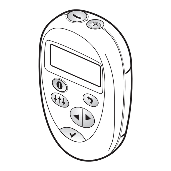
Programmer The clinician programmer is an external device that is used to program the stimulation parameters of Brio™ neurostimulators via RF telemetry. Controller The patient controller allows the patient to check the status of their Brio™ IPG, adjust its amplitude (optional), and turn it on or off. -
Page 17: Suggested Implant Guidelines
S U G G E S T E D I M P L A N T G U I D E L I N E S The implanting surgeon should carefully review the following suggested guidelines for implantation of the Brio™... -
Page 18: Placing The Ipg
CAUTION: Use only the torque wrench included in the extension, IPG, or torque wrench kit . If you need to loosen the setscrew, turn the setscrew (in quarter turns counterclockwise) just enough to insert or remove the extension from the IPG connector assembly . Loosening the setscrew too far will cause it to fall out . Tighten clockwise F I G U R E 3 Repeat steps 2-4 for the other extension. - Page 19 Carefully coil any excess extension in loops no smaller than 2.5 cm (1 in) in diameter and place them behind the IPG (see Figure 4). F I G U R E 4 To stabilize the IPG within the pocket and minimize movement, pass a suture through a suture hole at the top of the IPG header (see Figure 2) and secure it to the connective tissue.
-
Page 20: Replacing The Ipg
E X P L A N T E D C O M P O N E N T D I S P O S A L Explanted components should be returned to St. Jude Medical for proper disposal. To return an explanted component, place it in a container or bag marked with a biohazard label and coordinate the return with your St. -
Page 21: Clinician Programmer
NOTE: Each time before using the system, inspect the device and its accessories for damage. Avoid using a damaged device or accessory. Return it to St. Jude Medical for evaluation. The general flow of the programmer operation is as follows: •... -
Page 22: Demo Mode
Demo Mode A demo mode is available in the clinician programmer. Demo mode is intended as a training tool to practice using the programmer prior to using it during an actual programming session. All of the major functions of the programmer are simulated in demo mode. Entering Demo Mode With the programmer off Place the communication wand at least 20 cm (8 in) away from all neurostimulators, computers, or... -
Page 23: Basic Operation And The Home Screen
Basic Operation and the Home Screen This section provides an overview of the most commonly used features of the programmer. See the “Programming Mode” section of this manual for instructions on programming the IPG. Turning the Programmer On To turn on the programmer and establish communication with the IPG, follow these steps: Ensure the wand connector is fully inserted in the wand receptacle on the bottom of the programmer. -
Page 24: Turning Stimulation On
Use the scroll buttons to change the function displayed in the Home option window in the lower right corner, then use the green button to select that action. The Home option window choices are shown below. The programmer hides (does not offer) choices that are incompatible with the current stimulation program and neurostimulator status. -
Page 25: Setting Programmer Preferences
Setting Programmer Preferences Use the PREF menu to adjust the volume, backlighting, or contrast of the programmer, or view programmer and IPG information. On the Home screen use the scroll buttons to highlight PREF in the lower right corner. Press the green button. -
Page 26: Using Amplitude Adjustment Mode
Using Amplitude Adjustment Mode Amplitude adjustment mode is accessible from the Home screen when amplitude limits have been enabled. See “SET AMP LIMITS” for information on enabling amplitude adjustment mode. See the “Understanding the Home Screen” section for information on accessing amplitude adjustment mode. In this mode, the buttons can be used to adjust stimulation amplitude in the same way that a patient would with a Brio™... - Page 27 When in the programming mode, select between GO TO LEAD 1 or GO TO LEAD 2 to start programming. The following selection menu will be displayed: The sequence of menu selections in the programming mode is shown in the following diagrams (sample program screens are used).
-
Page 28: Amplitude Menu
Amplitude Menu The amplitude menu contains four options: AMP, STEP, JUMPTO, and EXIT (see the following image). Each of these options is described in the following subsections. Use this option to set the amplitude of the stimulation generated by the neurostimulator. NOTE: When programming lead 1 (electrodes 1-8), the amplitude line will read AMP1. -
Page 29: Step
STEP Use this option to set the increment by which AMP will be adjusted both in programming mode, and in amplitude adjustment mode. Highlighting this line and pressing: increases STEP by 0.05 mA decreases STEP by 0.05 mA This line shows the increment by which the stimulation amplitude will be increased or decreased when the AMP line is highlighted and the button is pressed. -
Page 30: Exit
EXIT Use this option to exit programming mode and return to the Home screen. Highlighting the EXIT line on either the Amplitude or Configuration screen and pressing: exits programming mode and provides the choice of saving or discarding the changes made to the program or returning to programming mode. -
Page 31: Can
Use this option to set the polarity of the neurostimulator case (CAN). Highlighting this line and pressing: toggles the can polarity between ANODE and OFF toggles the can polarity between ANODE and OFF The neurostimulator case can be programmed to be either: ANODE (a positive electrode, for monopolar stimulation), or OFF (not part of the stimulation circuit, for bipolar stimulation). -
Page 32: Freq
The programmer supports programming one or two leads with up to 8 electrodes per lead. The electrodes on lead 1 are numbered 1 through 8, with the most distal electrode designated electrode 1. Similarly, the electrodes on lead 2 are numbered 9 through 16, with the most distal electrode designated electrode 9. Electrode polarities are indicated as follows: Electrode 1 = (0) OFF Electrode 2 = (–) CATHODE... -
Page 33: Actions Menu
Actions Menu The action menu contains four options: CHECK IMPEDANCE, SET AMP LIMITS, GET STIM TIME, and RAMPTIME (see the following image). Each of these options is described in the following subsections. CHECK IMPEDANCE Use this option to obtain the impedance of the lead with the current electrode configuration. Highlighting this line and pressing: starts the impedance measurement sequence. -
Page 34: Set Amp Limits
SET AMP LIMITS Use this option to enable and set the values of the amplitude limits or to disable amplitude limits. Highlighting this line and pressing: enters the amplitude limits configuration screen The Brio™ neurostimulation system gives you the ability to allow your patients to adjust their stimulation amplitude using their controller within the limits that you prescribe. -
Page 35: Ramptime
RAMPTIME Use this option to set how long it will take to ramp stimulation up to the programmed amplitude when the neurostimulator is turned on. Highlighting this line and pressing: moves to the next longer ramp time moves to the next shorter ramp time Some patients may find it more comfortable to have stimulation gradually ramp up when the neurostimulator is turned on, rather than jumping directly to the programmed amplitude. -
Page 36: Configuration Menu
The programmer uses the electrode dimensions to calculate the average charge density and displays a warning when it exceeds 30 µC/cm . St. Jude Medical recommends that charge density not be exceeded. Each time the programmer is turned on, it resets this parameter to the smallest electrode dimensions. See the manual packaged with the DBS lead to determine the lead dimensions. -
Page 37: Magnet Settings
After entering the stimulation mode adjustment screen, use the buttons to toggle between CONT (continuous) and CYCLE modes. When CYCLE is selected use the scroll butt ons and buttons to adjust the H (hours), M (minutes), and S (seconds) for the cycle on and cycle off times in the stimulation mode adjustment screen. -
Page 38: Switch Menu
Switch Menu GO TO LEAD 1 / GO TO LEAD 2 Use these options to move to (and program) the other lead on the Brio™ neurostimulator. The following screen will be displayed to select lead 2 when programming lead 1. Lead 1 will be available for selection when programming lead 2. -
Page 39: Troubleshooting
A rechargeable IPG will need replacement when stimulation can no longer be maintained with routine recharging. Battery usage studies demonstrate that, when used at high stimulation parameters, the Brio battery should allow at least ten years of practical recharging. At high stimulation parameters, a ten-year- old device will maintain at least 24 hours of continuous therapy between recharges. -
Page 40: Impedance Measurements
Impedance Measurements Impedance measurements can be helpful for troubleshooting problems. To obtain an impedance measurement, enter programming mode and use the CHECK IMPEDANCE action. After the impedance measurement is taken, the screen will appear as shown in the following image. Impedance in ohms Keep in mind the following when interpreting impedance measurements: RETRY. -
Page 41: High Charge Density
High Charge Density The programmer automatically checks every amplitude and pulse width increase request to determine if it would cause the charge density to exceed 30 µC/cm . If so, it displays the charge density warning shown in the following image. Selecting YES sends the requested increase to the neurostimulator and allows you to exceed the limit. - Page 42 The following message appears when the programmer detects that its batteries are low. Remove the battery pack from the back of the programmer and replace the batteries with 3 new AAA batteries as shown. 3 AAA alkaline batteries Battery pack NOTE: Do not use rechargeable batteries.
-
Page 43: Ipg Heating During Charging
C U S T O M E R S E R V I C E I N F O R M A T I O N For help with a St. Jude Medical neuromodulation product, including technical service or repairs, contact Customer Service using the following information: St. -
Page 44: Warranty
B. St. Jude Medical makes no representations or warranties that failure or cessation of function of any component, or the system, will not occur; that the body will not react adversely to implantation; or that medical complications will not develop. - Page 45 A. Subject to Sections I and II and paragraph III(B) of this limited warranty, if any of the implantable components should fail to function due to a defect in material or workmanship during the warranty period, St. Jude Medical will, at its option: 1.
-
Page 46: Appendix A: Ipg Specifications And Kit Components
A P P E N D I X A : I P G S P E C I F I C A T I O N S A N D K I T C O M P O N E N T S IPG Specifications Model Number 6788... -
Page 47: Appendix B: Brio Clinician Programmer Specifications And Kit Components
A P P E N D I X B : B R I O C L I N I C I A N P R O G R A M M E R S P E C I F I C A T I O N S A N D K I T C O M P O N E N T S Programmer Specifications Model Number... -
Page 48: Appendix C: Brio System And Mri Safety
A P P E N D I X C : B R I O S Y S T E M A N D M R I S A F E T Y Performing an MRI in patients implanted with this DBS system is contraindicated. MRI examinations of patients implanted with this DBS system should only be done if absolutely necessary and then only if these guidelines are followed. -
Page 49: Gradient Magnetic Fields
indicator head center. The Brio system with leads coiled at least 3 times near the burr hole (main lead coil plane perpendicular to BO; for more information on the effects of loops see the Baker reference) produced a maximum temperature rise of ≈6.5°C in a static human-shaped phantom with a background temperature increase of ≈0.4°C at a displayed head averaged (HA) specific absorption rate (SAR) of “3.1”... -
Page 50: Mri Safety Guidelines
MRI Safety Guidelines Implant Recommendations • The Brio™ DBS system should be implanted as close to the centerline of the patient as possible, avoiding unnecessary offset of system components. Placement of system components further from the centerline will induce increased system heating at the exposed electrodes and may result in greater patient risk of severe injury or death •... -
Page 51: Mri Scanner Parameters And Settings
CAUTION: Due to the risk of localized heating that may result in tissue damage, MRI procedures should not be performed on patients with any DBS system that is suspected to have a broken lead or extension wire . If a broken lead or extension wire is suspected, an X ray should be obtained prior to an MRI to verify the presence of the broken wire . -
Page 52: Appendix D: Electromagnetic Compatibility Guidelines
A P P E N D I X D : E L E C T R O M A G N E T I C C O M P A T I B I L I T Y G U I D E L I N E S The Brio™... - Page 53 Guidance and Manufacturer’s Declaration – Electromagnetic Immunity Immunity Test IEC 60601 Test Level Compliance Level Electromagnetic Environment Guidance Voltage dips, short <5% U Not applicable No guidance for battery-powered devices. interruptions 40% U IEC 61000-4-11 70% U Power frequency (50/60 Hz) 30 A/m 30 A/m Power frequency magnetic fields should be at...
-
Page 54: Appendix E: Ce Mark Date
A P P E N D I X E : C E M A R K D A T E The following table lists the year in which the CE mark was awarded by model number. Model Year 1101 1999 1210, 1232, 1253, 1272 2000 1111... - Page 56 St. Jude Medical St. Jude Medical St. Jude Medical Australia Pty. Limited 6901 Preston Road Coordination Center BVBA 17 Orion Road Plano, Texas 75024 The Corporate Village Lane Cove NSW 2066 Da VinciIaan 11 Box F1 Australia +1 972 309 8000 1935 Zaventem Belgium +32 2 774 68 11 St. Jude Medical Puerto Rico LLC...
Need help?
Do you have a question about the Brio 6788 and is the answer not in the manual?
Questions and answers