Table of Contents
Advertisement
Quick Links
Advertisement
Table of Contents

Related Manuals for St. Jude Medical Proclaim DRG 3664


Summary of Contents for St. Jude Medical Proclaim DRG 3664
- Page 1 Proclaim™ DRG Implantable Pulse Generator Model 3664 Clinician's Manual...
- Page 2 Unless otherwise noted, ™ indicates that the name is a trademark of, or licensed to, St. Jude Medical or one of its subsidiaries. ST. JUDE MEDICAL and the nine-squares symbol are trademarks and service marks of St. Jude Medical, LLC and its related companies.
-
Page 3: Table Of Contents
Contents Prescription and Safety Information ..................1 Intended Use ........................1 Indications for Use ....................... 1 Contraindications ......................... 1 MRI Safety Information ......................2 Warnings ..........................2 Precautions......................... 8 Adverse Effects........................14 System Overview........................16 Product Description ......................18 Package Contents ......................19 Identifying the IPG ...................... - Page 4 Disposing of Explanted Components..................29 Checking the Status of the IPG Battery ................29 Technical Support ........................ 30 Appendix A: Product Specifications ..................30 Storage Specifications ......................31 Product Materials....................... 31 IPG Specifications......................32 Appendix B: System Components and Accessories ............. 34 IPGs..........................
- Page 5 Appendix D: Sy mbols and Definitions ................... 43 Additional Symbols for Product Labels.................. 47 Appendix E: CE Mark Date ....................48...
-
Page 7: Prescription And Safety Information
Prescription and Safety Information Read this section to gather important prescription and safety information. Intended Use This neurostimulation system is designed to deliver low-intensity electrical impulses to nerve structures. The system is intended to be used with leads and associated extensions that are compatible with the system. -
Page 8: Mri Safety Information
MRI Safety Information Some models of this system are Magnetic Resonance (MR) Conditional, and patients with these devices may be scanned safely with magnetic resonance imaging (MRI) when the conditions for safe scanning are met. For more information about MR Conditional neurostimulation components and systems, including equipment settings, scanning procedures, and a complete listing of conditionally approved components, refer to the MRI procedures clinician's manual for neurostimulation systems (available online at manuals.sjm.com). - Page 9 Magnetic resonance imaging (MRI). Some patients may be implanted with the components that make up a Magnetic Resonance (MR) Conditional system, which allows them to receive an MRI scan if all the requirements for the implanted components and for scanning are met. A physician can help determine if a patient is eligible to receive an MRI scan by following the requirements provided by St.
- Page 10 electrosurgery device, place the device in Surgery Mode using the patient controller app or clinician programmer app. Confirm the neurostimulation system is functioning correctly after the procedure. During implant procedures, if electrosurgery devices must be used, take the following actions: Use bipolar electrosurgery only.
- Page 11 device in a unipolar mode (using the device’s can as an anode) or using neurostimulation system settings that interfere with the function of the implantable cardiac system. Emergency procedures. Instruct patients to designate a representative (family member or close friend) to notify any emergency medical personnel of their implanted neurostimulation system if emergency care is required.
- Page 12 linear accelerators. If radiation therapy is required, the area over the implanted IPG should be shielded with lead. Damage to the system may not be immediately detectable. Restricted areas. Warn patients to seek medical guidance before entering environments that could adversely affect the operation of the implanted device, including areas protected by a warning notice preventing entry by patients fitted with a pacemaker.
- Page 13 Advise patients to not use their device when engaging in activities that might cause it to get wet, such as swimming or bathing. Device components. The use of components not approved for use by St. Jude Medical with this system may result in damage to the system and increased risk to the patient.
-
Page 14: Precautions
IPG disposal. Return all explanted IPGs to St. Jude Medical for safe disposal. IPGs contain batteries as well as other potentially hazardous materials. Do not crush, puncture, or burn the IPG because explosion or fire may result. Product materials. Neurostimulation systems have materials that come in contact or may come in contact with tissue. - Page 15 Implantation of multiple leads. If multiple leads or extensions are implanted, the leads and extensions should be routed in close proximity. Nonadjacent leads and extensions have the possibility of creating a conduit for stray electromagnetic energy that could cause the patient unwanted stimulation. High stimulation outputs.
- Page 16 Storage environment. Store components and their packaging where they will not come in contact with liquids of any kind. Handling and Implementation Expiration date. An expiration date (or “use-before” date) is printed on the packaging. Do not use the system if the use-before date has expired. Package or component damage.
- Page 17 Component handling. Do not bend, kink, or stretch the lead body, sheaths, or other components as this may result in damage to the component and poor function. Using surgical instruments. Do not use surgical instruments to handle the lead. The force of the instruments may damage the lead or stylet.
- Page 18 System testing. To ensure correct operation, always test the system during the implant procedure, before closing the neurostimulator pocket, and before the patient leaves the surgery suite. Component disposal. Return all explanted components to St. Jude Medical for safe disposal. Hospital and Medical Environments High-output ultrasonics and lithotripsy.
- Page 19 furnaces), communication equipment (such as microwave transmitters and high-power amateur transmitters), high-voltage power lines, radiofrequency identification (RFID) devices, some medical procedures (such as therapeutic radiation and electromagnetic lithotripsy), and some medical devices (such as bone growth stimulators, transcutaneous electrical nerve stimulation [TENS] devices, dental drills, and ultrasonic probes).
-
Page 20: Adverse Effects
Mobile phones. While interference with mobile phones is not anticipated, technology continues to change and interaction between a neurostimulation system and a mobile phone is possible. Advise patients to contact their physician if they are concerned about their mobile phone interacting with their neurostimulation system. - Page 21 Pain or bleeding where the needle was inserted Persistent pain at the electrode or IPG site Escalating pain Seroma (mass or swelling) at the implant site Headache Allergic or rejection response to device or implant materials ...
-
Page 22: System Overview
System Overview This neurostimulation system is designed to deliver electrical stimulation to nerve structures. The neurostimulation system includes the following main components: Implantable pulse generator (IPG) Leads Clinician programmer Patient controller Patient magnet The IPG delivers electrical pulses through the leads to electrodes near selected nerve fibers in order to provide therapeutic stimulation. - Page 23 The following image shows how the major system components are intended to interact. Figure 1. Interaction among main system components 1. Clinician programmer or patient controller 2. IPG 3. Leads 4. Patient magnet...
-
Page 24: Product Description
For more information about IPG features and specifications, see the appropriate appendix in this manual. NOTE: In this document, the term "clinician programmer" refers to the St. Jude Medical™ Clinician Programmer device, "patient controller" refers to the St. Jude Medical™ Patient Controller device, "clinician programmer app"... -
Page 25: Package Contents
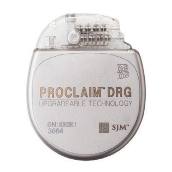
The tag, which is located in the lower left corner of the IPG when the logo side of the IPG is facing toward you, contains a code in the following format: SJMLN. SJM designates St. Jude Medical as the manufacturer; LN is a letter and a number combination that identifies the model family (see the following figure). -
Page 26: Directions For Use
Figure 2. Location of the IPG code on the IPG Directions for Use Read this section carefully for suggested directions for use related to the IPG. For directions for use for other system components not covered in this document, see the clinician’s manual for the appropriate device. -
Page 27: Creating An Ipg Pocket
first activate the IPG for communication ("wake up" the IPG) by holding a magnet over the IPG for 8 seconds. Creating an IPG Pocket The following steps outline the suggested procedure to create an IPG pocket: Determine the site for the IPG, ensuring that the lead is long enough to reach the pocket and provide a strain relief loop. -
Page 28: Connecting A Lead Or Extension To The Ipg
Connecting a Lead or Extension to the IPG The following steps outline the suggested guidelines to connect a lead or extension to the IPG: WARNING: To avoid harming the patient or damaging the neurostimulation system, ensure that any electrosurgery procedures are completed before connecting the lead or extensions to the IPG. - Page 29 of the header port (see the following figures). Figure 3. Locations of the ports on the IPG header 1. Port 1 (electrodes 1 to 4) 2. Port 2 (electrodes 5 to 8) 3. Port 3 (electrodes 9 to 12) 4. Port 4 (electrodes 13 to 16)
- Page 30 Figure 4. Insert the lead or extension fully into the IPG header Fully inserted 1. Window between each header contact is clear 2. Indicator band aligns with opening of header port Not fully inserted 3. Window between each header contact is partially blocked by contact band 4.
- Page 31 Figure 5. Tighten the setscrew clockwise 1. Septa for the setscrews for ports 1 and 2 are on the respective sides of the IPG header. 2. Septa for the setscrews for ports 3 and 4 are on top of the IPG header. If implanting multiple leads, repeat the previous steps for each lead.
-
Page 32: Implanting The Ipg
Figure 6. Insert the port plug Implanting the IPG The following steps outline the suggested procedure to implant the IPG: Place the IPG into the IPG pocket with the logo side facing the skin surface and at a depth not to exceed 4.0 cm (1.57 in). - Page 33 NOTE: By implanting the IPG with the logo side facing the skin surface, you enhance the IPG's ability to detect a magnet. Carefully coil any excess lead or extension behind the IPG in loops no smaller than 2.5 cm (1 in) in diameter to provide strain relief for the lead or extension and IPG connection.
-
Page 34: Replacing The Ipg
Replacing the IPG The following steps outline the suggested procedure to replace an IPG: Turn off stimulation or verify that it is turned off. CAUTION: Exercise care when using sharp instruments or electrocautery around leads or extensions, or they may be damaged. Open the IPG implant site per normal surgical procedure. -
Page 35: Disposing Of Explanted Components
Disposing of Explanted Components Explanted St. Jude Medical™ components should be returned to St. Jude Medical for proper disposal. To return an explanted component, place it in a container or bag marked with a biohazard label and coordinate the return with your St. Jude Medical representative or Technical Support. -
Page 36: Technical Support
Stimulation will automatically stop when the battery cannot support stimulation. Technical Support For technical questions and support for your St. Jude Medical™ neuromodulation product, use the following information: +1 972 309 8000 +1 800 727 7846 (toll-free within North America) ... -
Page 37: Storage Specifications
Storage Specifications Store the components according to the following conditions. Table 1. Storage conditions for components Temperature -20°C–60°C (-4°F–140°F) Product Materials The following materials are intended to come into contact with tissue. Table 2. Product materials for IPG kit Component Material Titanium, silicone rubber, epoxy resin Pocket sizer... -
Page 38: Ipg Specifications
IPG Specifications The Proclaim™ DRG IPG has the following physical specifications. Table 3. IPG specifications Model 3664 Height 6.09 cm (2.40 in) Length 4.95 cm (1.95 in) Thickness 1.34 cm (0.53 in) Weight 52.0 g (1.8 oz) Volume 32.0 cm (2.0 in Estimated battery longevity (nominal settings)* 6.5 years... - Page 39 Table 3. IPG specifications * Battery longevity was estimated using the following nominal settings for a dual-lead system with a one- year shelf life 24 hours per day: 20-Hz frequency, 300-μs pulse width, and 0.8-mA amplitude at 1600-ohms impedance. For information on how additional settings may impact the longevity of the device, please contact Technical Support.
-
Page 40: Appendix B: System Components And Accessories
NOTE: Not all models are available in all countries. Contact your local representative for more information. IPGs 3664 Proclaim™ DRG implantable pulse generator IPG Accessories 7108 Port plug, DRG Programmers and Controllers 3874 St. Jude Medical™ Clinician Programmer App 3875 St. Jude Medical™ Patient Controller App... -
Page 41: Leads And Extensions
Programmer and Controller Accessories 1210 Patient magnet 7884 Proclaim™ DRG patient manual and magnet Leads and Extensions MN20450-series implant leads (standard and SlimTip™ leads) MN20550-50 50-cm lead extension kit Lead and Extension Accessories MN15000 Tunneling tool kit MN22050 Lead accessories kit MN22150 22-cm small curve delivery sheath kit MN23650... -
Page 42: Trial System
Trial System MN20100 Axium™ trial neurostimulator Trial System Accessories MN20350-series trial leads (standard and SlimTip™ leads) MN20700 Axium™ clinical programmer kit MN20500-02 Axium™ patient programmer kit MN21350 Axium™ connector cable kit Appendix C: Regulatory Statements This section contains regulatory statements about your product. Disposal Guidelines for Battery-Powered Devices This device contains a battery and a label is affixed to the device in accordance with European Council directives 2002/96/EC and 2006/66/EC. -
Page 43: Statement Of Fcc Compliance
Return the device to St. Jude Medical at the end of its operating life. Statement of FCC Compliance This equipment has been tested and found to comply with the limits for a Class B digital device, pursuant to part 15 of the FCC rules. -
Page 44: Statement Of Compliance With License-Exempt Rss Standard (Canada)
This device must accept any interference received, including interference that may cause undesired operation. Modifications not expressly approved by the manufacturer could void the user’s authority to operate the equipment under FCC rules. Statement of Compliance With License-Exempt RSS Standard (Canada) This device complies with Industry Canada license-exempt RSS standard(s). -
Page 45: Wireless Technology Information
Wireless Technology Information The following table summarizes the technical details of the Bluetooth ® Smart wireless technology as it is implemented in the device. Table 6. Bluetooth Smart wireless technology information Antenna type Embedded patch antenna in header Antenna dimensions 8.1 mm x 5.1 mm x 4.9 mm Modulation GFSK... -
Page 46: Radio Transmitter, Cables, Transducers
Table 6. Bluetooth Smart wireless technology information *EIRP = Equivalent isotropically radiated power Radio Transmitter, Cables, Transducers The device contains a radio transmitter/receiver with the following parameters. Radio transmitter parameters: Frequency (range): 2.4000 to 2.4835 GHz Bandwidth (-15dB): 2.398 to 2.4855 GHz ... -
Page 47: Quality Of Service For Wireless Technology
The radio receiver in the device is using the same frequency and bandwidth as the transmitter. Cables and transducers: Cables and transducers are not used during normal use of the device nor while programming the device. Quality of Service for Wireless Technology Bluetooth ®... - Page 48 successfully. Each key press may transmit up to 8 data packets, depending on the number of packets that need to be transmitted (i.e., if there is only one packet to transmit, only one packet will be transmitted). Wireless Security Measures The wireless signals are secured through device system design that includes the following: The generator will encrypt its wireless communication.
- Page 49 Move the devices so they share line of sight Move the devices away from other devices that may be causing interference Wait a few minutes and try connecting again Do not operate other wireless devices (i.e., laptop, tablet, mobile phone, or cordless phone) at the ...
- Page 50 Follow instructions for use on this website Magnetic Resonance (MR) Conditional, an item with demonstrated safety in the MR environment within the defined conditions. At a minimum, address the conditions of the static magnetic field, the switched gradient magnetic field, and the radiofrequency fields. Additional conditions, including specific configurations of the item, may be required.
- Page 51 Manufacturing facility Temperature limits for storage conditions Do not use if the product sterilization barrier or its packaging is compromised Catalog number Manufacturer Contents quantity Pulse generator Accessories Serial number Batch code...
- Page 52 Authorized European representative European conformity, affixed according to the relevant provisions of AIMD directive 90/385/EEC and RE directive 2014/53/EU Annex II. Hereby, St. Jude Medical declares that this device complies with the essential requirements and other relevant provisions of these directives.
- Page 53 Additional Symbols for Product Labels The following table shows additional symbols that may appear on the product labels for parts related to this kit. Table 8. Additional symbols for product labels Symbol Definition Port plug, DRG Implantable pulse generator...
- Page 54 Appendix E: CE Mark Date The following table lists the year in which the CE mark was awarded from the applicable notified body by model number. Table 9. Year in which CE mark was awarded Model Year Notified Body 3664, 7108 2016 0086...
- Page 56 +32 2 774 68 11 Manufacturing Site: Manufacturing Site: St. Jude Medical Puerto Rico LLC St. Jude Medical Operations (M) Sdn. Bhd. Lot A Interior - #2 Rd Km. 67.5 Plot 102, Lebuhraya Kampung Jawa, Santana Industrial Park Bayan Lepas Industrial Zone...
Need help?
Do you have a question about the Proclaim DRG 3664 and is the answer not in the manual?
Questions and answers