Table of Contents
Advertisement
Quick Links
Advertisement
Table of Contents

Related Manuals for RADWAG WPT EX Series


Summary of Contents for RADWAG WPT EX Series
- Page 1 EXI-01-04-06-14-GB B A L A N C E S A N D S C A L E S RADWAG 26 – 600 Radom, Bracka 28, POLAND Phone +48 48 38 48 800, phone/fax: +48 48 385 00 10 Sales department +48 48 366 80 06...
- Page 2 JUNE 2014 "The drawings, photos and graphics EXI-01-04-06-14-GB - 2 - used are for illustrative purposes only."...
-
Page 3: Table Of Contents
TABLE OF CONTENTS 1. DESIGN AND INTENDED USE ..................4 2. SECURITY REQUIREMENTS..................... 6 2.1. ATEX marking – symbols meaning ................7 2.2. Rating plates for indicator and scale ................8 2.3. Placement of information stickers ................9 3. START-UP ........................10 3.1. -
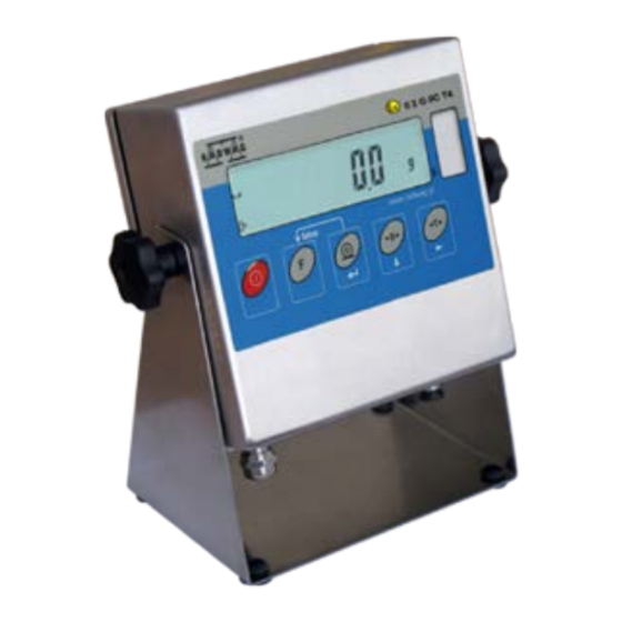
Page 4: Design And Intended Use
1. DESIGN AND INTENDED USE Indicator of PUE C/31H/EX type, in cooperation with a weighing platform, is intended for fast and precise measurements performed in explosive areas. Tarring throughout the whole measuring range allows to determine the net mass of measured loads. The PUE C/31H/EX series indicator consists of: •... - Page 5 PUE C/31H/EX technical data: PUE C/31H/EX Housing type stainless steel Ingress Protection Rating IP66/67 Display type Keyboard Microswitch (500 000 cycles) OIML class Maximum quantity of A/D converter divisions 8388608 Number of verification intervals 6 000 Maximum input voltage 19,5 mV 3,25 µV Maximum voltage per verification interval 1 µV...
-
Page 6: Security Requirements
• Power supplied from the ZRi02 power supplier II (2) G [Ex ib] IIC KDB 06ATEX251 manufactured by RADWAG, placed behind the hazardous area or from another adapter with appropriate parameters of intrinsically safe electrical circuit. •... -
Page 7: Atex Marking - Symbols Meaning
2.1. ATEX marking – symbols meaning Equipment group: Electrical equipment - Temperature class – I – underground parts compatible with one or surface max temperature of mines few kinds of anti- of the equipment parts that explosion designs II – all other places liable are in touch with explosive to be endangered by mixture... -
Page 8: Rating Plates For Indicator And Scale
PUE C/31H/EX indicator is a device of group II with „ib” protection therefore “Gb” protection symbol may be omitted. 2.2. Rating plates for indicator and scales Rating plate of the scale (exemplary) Rating plate of the PUE C/31H/EX indicator 1 – Manufacturer’s Logo 2 –... -
Page 9: Placement Of Information Stickers
10 – WEEE symbol 11 – ATEX marking relating to the scale (see point 2.1) 12 – EX marking stating that the device is intended for operation in explosive areas 13 – accuracy class marking 14 – certificate number of used load cell 15 –... -
Page 10: Start-Up
Rating plate of the scale Protective sticker Verification sticker Functional grounding mark START-UP Please read this manual carefully prior the start-up. Following the instruction, use the device as intended. 3.1. Scale placing • The scale should be unpacked outside the hazardous area. •... -
Page 11: Connecting Power Supplier
Scales with PUE C/31H/EX indicators can be supplied only from ZRi02 power suppliers II (2) G [Ex ib] IIC KDB 06ATEX251 of RADWAG production, placed outside the hazardous area, or from another supplier characterized by below presented parameters of intrinsically safe electrical circuit. - Page 12 Safe area Hazardous area EX ZRi02 power supplier cable up to 20m AC 230v 50Hz Scale with the indicator on a pillar Safe area Hazardous area EX ZRi02 power supplier cable up to 20m AC 230v 50Hz Scale with the indicator on a cable Supplier connection EXI-01-04-06-14-GB - 12 -...
- Page 13 1 – earthing terminal 2 – power supply socket description 3 – power supply socket 4 – power supply socket 5 – screened load cell cable Power connector parameters EXI-01-04-06-14-GB - 13 -...
-
Page 14: Switching On
3.3. Switching on • Press the ON/OFF key – keep pressing for about 1 sec. • After switching on, wait for the test completion. • The indication shall equal zero and the following pictograms shall be seen: - zero indication - equilibrium - weighing mode •... -
Page 15: Functions
In case of any problems with appropriate operation of the indicator, contact the manufacturer’s service centre or any service centre authorised by RADWAG. In case of any fault or dysfunction the device should be passed to the manufacturer’s service centre or, if this is not possible, the fault should be reported in order to settle the conditions of repair. -
Page 16: Keyboard
KEYBOARD Information window Display window Function keys – „keypad” FUNCTINS OF KEYS Power on/off – keep it pressed for about 1 sec Function key (selection of operation mode) Confirmation of changes - zeroing - tarring NOTICE: Pressing keys results in change of particular keys functions, wherein the change is valid until setting parameters procedure is completed. -
Page 17: Inscriptions And Pictograms
INSCRIPTIONS AND PICTOGRAMS O.n. Inscription Description Filtering level Parts counting HiLo +/- control in relation to reference mass Auto Control and correction of zero indication of scale Measurement of max. force influencing weighing pan Totalizing Scale in autozero range (indication = precise zero) Result of measurement is stable (ready for readout) Scale in operating mode counting pieces kg (g) -
Page 18: Browsing User's Menu
P3 Unit P3.1 StUn P4 Func P4.1 FFun P4.2 Funi P4.3 P4.4 HiLo P4.5 PrcA P4.6 Prcb P4.7 AtAr P4.8 P4.9 P6 CAL P6.1 St_u * FUNCTION * P6.2 uCAL * FUNCTION * BROWSING USER’S MENU User moves in the menu using the scale keyboard. 11.1. -
Page 19: Return To Weighing
11.2. Return to weighing NOTICE: Changes introduced into the scale memory will be permanently saved after return to weighing. Press F key several times, keep pressing until message <SAvE?> is seen. Return to weighing Upon noticing the message press: key – for changes confirmation or key –... -
Page 20: Tarring By Inscribing Tare Value
function pay attention to maximum weighing range, it cannot be exceeded. After removing the load and the package, display shows indication of sum of tarred weights with minus sign. NOTICE: Tarring may not be performed when minus value or zero is displayed. In such a case the display shows <Err3>... -
Page 21: Zeroing
NOTICE: Tarring by inscribing tare value cannot be performed when the tare value has already been implemented into the scale memory. In such a case the display shows <Err3> message, short sound signal is heard. 12.3. Zeroing In order to zero the indication press zeroing key - . -
Page 22: Setting Of Basic Unit For Weighing
12.5. Setting a basic weighing unit The user may set a weighing unit to be active after turning on the scales. Procedure: • Following point 11 of this manual enter <P3.Unit> submenu, next: • Press key several times to view available units: Selection: A. -
Page 23: Temporary Weighing Unit
Save changes and return to weighing: See point - 11.2. – return to weighing. NOTICE: Upon activation the scale operates with a set basic unit. 12.6. Temporary weighing unit This function allows users to choose unit for indication. The unit is valid until the scale is switched off or until another unit is chosen. -
Page 24: Main Parameters
MAIN PARAMETERS User can adjust the scale to external ambient conditions (setting filters) or individual requirements (autozero, tare value). Respective parameters can be found in <P1.rEAd> parameters group. 13.1. Adjustment of filtering level Procedure: • Following point 11 of this manual enter <P1.rEAd> submenu, next: 1 - 4 - filtering levels to be selected (depending on the ambient conditions) Return to weighing:... -
Page 25: Autozero
13.2. Autozero „AUTOZERO” function has been introduced in order to ensure precise indication. The intended use of this function is automatic control and correction of zero indication. When function is active comparison of results takes place at specified time intervals. If results differ by value smaller than declared AUTOZERO range, e.g. -
Page 26: Tare Function Operation
13.3. Tare function operation This function enables the user to set appropriate parameters (depending on needs) for tare function. Procedure: • Following point 11 of this manual enter <P1.rEAd> submenu, next: tArA AtAr automatic tare function on - stored in scale memory after unplugging it from mains (see point 15.5 for description);... -
Page 27: Median Filter
13.4. Median filter The role of the median filter is to eliminate short lasting interference (e.g. mechanical shocks). Procedure: • Following point 11 of this manual enter <P1.rEAd> submenu, next: Fnnd - median filter disabled Fnnd YES - median filter enabled Return to weighing: See point - 11.2. -
Page 28: Determining The Minimal Mass
13.5. Determining the minimal load S_Lo parameter works for automatic tare. The rule is that no automatic tare is performed until the indication drops below S_Lo value (gross). Procedure: • Following point 11 of this manual enter <P2.Prnt> submenu, next: Select the digit to be set Select the digit value Return to weighing:... -
Page 29: Determining Number Of Accessible Modes
- mode disabled YES - mode enabled NOTICE: Enabling procedure for other operation modes is analogous to the one described above. Return to weighing: See point - 11.2. – return to weighing. 14.2. Determining number of accessible modes The user may decide whether upon pressing F key all the operation modes are to be accessible (option <ALL>), or only one, selected out of the list. -
Page 30: Counting Parts Of Identical Weight
Return to weighing: See point - 11.2. – return to weighing. 14.3. Counting parts of identical weight The standard solution is equipped with option of counting small pieces of the same mass. If parts counting is to be performed in a container, its weight must be recorded into the scale memory (the container must be tarred). - Page 31 • The blinking value on the display informs of quantity of a sample. By means of key, set quantity of a sample and press key to confirm: • If option <LASt> has been chosen than the most recent weight value of a single piece is displayed for 3 sec., the program proceeds to Parts Counting mode automatically setting the previously displayed value.
- Page 32 • Using keys, enter the demanded quantity of sample, where: - selection of the digit to be set, - selection of the digit value, • Press key for confirmation • <LoAd> message is displayed, the following window is seen: Pilsujący symbol Blinking symbol •...
-
Page 33: Control Referring To The Inscribed Standard Mass
3. If a single element weight is not greater than a reading unit, then message <Err5> is shown on the scale display (see point 19. Error Messages), short sound signal is heard, next the scale returns to weighing. Function deactivation: Press F key twice. - Page 34 • Press key to confirm, the program proceeds to window for setting the upper threshold (Max): Select the digit to be set Select the digit value • Press key to confirm, the program automatically returns to weighing with threshold values recorded into the memory. •...
-
Page 35: Per Cent Deviation With Reference To Standard Mass
14.5. Per cent deviation with reference to standard mass This program allows to measure deviation in per cent with reference to a standard mass. The standard mass can be estimated by weighing (PrcA function) or inscribed by a user (PrcB function). 14.5.1. -
Page 36: Standard Mass Inscribed To Scale Memory
Function deactivation: Press F key twice. 14.5.2. Standard mass inscribed to scale memory Procedure: • Enter <Prcb> function (first make the operation mode accessible - see point 14.1): • The program proceeds to the following window: Blinking symbol • Using keys, set the mass standard weight, where: - selection of the digit to be set,... -
Page 37: Automatic Tare
Function deactivation: Press F key twice. 14.6. Automatic tare This function is useful for fast net mass determination of weighed load when the tare value for each next load to be weighed is different. In case when the function is active the cycle of scales operation looks as follows: •... -
Page 38: Measurement Of The Max Force - Peak Hold
14.7. Measurement of the max force – peak hold Procedure: • Enter <toP> function (first make the operation mode accessible - see point 14.1): • Max pictogram visible in upper part of the display is a confirmation of toP function activation: •... -
Page 39: Totalizing Procedure
• Enter <Add> function (first make the operation mode accessible - see point 14.1) • „P” letter visible on the left of the display is a confirmation of <Add> function activation: 14.8.2. Totalizing procedure • Following point 14.8.1 enter <Add> function, •... -
Page 40: Storing The Last Sum Of Weighings
• Upon indication stabilization press key, sum of the first and second weighing is displayed („▲” pictogram in the upper right-hand corner of the display): • In order to finish the procedure of totalizing, press (either with a load on the pan or after taking it off): •... -
Page 41: Adjustment
NOTICE: In case of a display range overflow in totalizing, the program displays error <5-FULL>. The user must either take the load off the pan and press key in order to complete totalizing or replace the load with another one (of lower mass) not resulting in display range overflow. - Page 42 • The following messages are displayed: • A new start mass is adjusted during this period of time. After that a mass of calibration weight is shown (e.g. 3 000kg). • Put the calibration weight on the weighing pan and press key, adjustment process starts, the following message is seen: •...
-
Page 43: Start Mass Estimation
• Take off the load, message <donE> is displayed for 1 sec., the scale shows the adjustment submenu name: • Adjustment process may be interrupted at any time by pressing key, the following message informs about abortion of a process: NOTICE: 1. - Page 44 • the program displays the following set of messages: • upon completion of the start mass estimation process the scale shows the parameter name: • start mass estimation process may be interrupted at any time by pressing key, the following message informs about abortion of a process: NOTICE: If the start mass estimation takes more than 15 sec.
-
Page 45: Errors
ERRORS Err2 Value beyond the zero range Err3 Value beyond the tare range Err4 Calibration mass or start mass beyond the acceptable range (±1% for weight, ±10 for start mass). Err5 Mass of a single piece lower than the scale division. Err7 Power down time was to short (should be over 3s) Err8... - Page 46 EXI-01-04-06-14-GB - 46 -...
- Page 47 MANUFACTURER O F E L E C T R O N I C E Q U I P M E N T RADWAG WAGI ELEKTRONICZNE POLAND, 26 – 600 Radom, Bracka 28 Phone: +48 48 38 48 800, phone/fax: + 48 48 385 00 10 Sales dpt.: + 48 48 366 80 06...
Need help?
Do you have a question about the WPT EX Series and is the answer not in the manual?
Questions and answers