Table of Contents
Advertisement
Quick Links
Advertisement
Table of Contents

Related Manuals for Kurtz Ersa i-CON TRACE 3BA00252-01


Summary of Contents for Kurtz Ersa i-CON TRACE 3BA00252-01
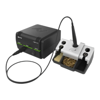
- Page 1 i-CON TRACE® IoT soldering station Operating instructions: 3BA00252-01 Ersa GmbH Leonhard-Karl-Str. 24 97877 Wertheim Phone +49 9342/800-136 www.ersa.de Fax +49 9342/800-132 Rev. 4 Mobile +49 171 241 846 8 Printing date: 11/07/2023 service-ersa@kurtzersa.de...
-
Page 3: Table Of Contents
Table of contents Table of contents For your safety ........................ 5 ESD sensitive components .......................... 9 FCC USA info.............................. 9 Introduction ........................ 11 Intended use ............................... 11 Copyright and liability .......................... 11 Warranty .............................. 11 Technical data ........................ 13 Electrical connection........................... 13 General data.............................. 13 Properties.............................. 13 Server PC minimum requirements...................... 14 Web browser minimum requirements ....................... 14 WLAN topology ............................ 14 Mobile device minimum requirements....................... 14... - Page 4 Table of contents Service and maintenance.................... 46 Error messages and error codes ......................... 46 Error treatment............................ 47 Cleaning and Maintenance ......................... 51 Defaults ............................... 53 Spare/wear parts and accessories .................. 54 3BA00252-01 | Rev. 4 Ersa GmbH...
-
Page 5: For Your Safety
For your safety For your safety Safety Notes Ersa products are developed, manufactured and tested in compliance with essen- tial safety requirements. Residual risks nevertheless remain! You should therefore read these instructions before you start to operate the tool for the first time. The instructions will help you operate the soldering tool safely as well as becoming acquainted with all functions and properly using them. - Page 6 For your safety WARNING Fire hazard due to hot soldering tool! a) Before switching on the soldering station, all easily combustible objects, li- quids and gases must be removed from the working area! b) Always place the soldering tool in the supporting stand when not in use! c) Disconnect the soldering station from the mains after use! CAUTION Risk of burns! The soldering iron gets hot immediately after it is switched on!
- Page 7 For your safety CAUTION Wear protective equipment! During soldering, hot solder or corrosive flux material can splatter from the solder joint. Avoid getting solder or flux material in the eyes or on the skin by wearing protective equipment! a) Adhere to the company’s internal regulations for protective clothing! b)Adhere to the safety data sheets for the solder and flux material used! WARNING Dangerous electrical voltage!
- Page 8 For your safety CAUTION Toxic fumes when soldering! During soldering, emissions are produced from the solder materials and the as- semblies. These emissions are harmful to health. Do not inhale the fumes! a) Ensure sufficient ventilation or use a solder fume extraction system! b) Adhere to the safety data sheets for the solder and flux materials used! WARNING Danger of fire and electric shock!
-
Page 9: Esd Sensitive Components
For your safety CAUTION Risk of accidents! Danger due to use by unauthorised persons! a) Ensure that unauthorised persons, especially children, do not have access to the soldering station! ESD sensitive components NOTE Working with sensitive components Some components can be damaged by electrostatic discharges. Observe the warn- ings on the packaging or ask the manufacturers or suppliers. - Page 10 For your safety ence when the device is operated in a commercial environment. This device gener- ates, uses and can even radiate radio frequency energy. If it is not installed and used in accordance with the operating instructions, it can cause radio traffic inter- ference.
-
Page 11: Introduction
Introduction Introduction Intended use ® The soldering tool i-CON TRACE was designed state-of-the-art and according to ap- proved technical safety regulations. However, residual risks may originate from the soldering tool, especially if it is operated improperly by untrained personnel or used for purposes other than those it is intended for. - Page 12 Introduction ment Terms of Ersa GmbH. In the event of improper use and tampering with the device, any warranty and liability claims of the purchaser against the manufacturer shall become void. 3BA00252-01 | Rev. 4 Ersa GmbH...
-
Page 13: Technical Data
Technical data Technical data Electrical connection Designation Line voltage (VAC) 220-240 Line frequency (Hz) 50-60 Fuse, slow blowing (A) Line voltage (VAC) 110-120 Line frequency (Hz) 50-60 Fuse, slow blowing (A) Secondary voltage (VAC) General data Station Width (mm) Depth (mm) Height (mm) Weight (kg) approx. -
Page 14: Server Pc Minimum Requirements
Technical data Designation Permissible ambient temperature 0-40 / 32-104 (°C / °F) Control technology SENSOTRONIC (PID behaviour) Function display Supply line, PVC, with female connector (m) Protection class According to MIL-SPEC/ESA standard ✓ VDE certified, EMC tested ✓ Anti-static surface, especially suitable for use ✓... -
Page 15: Communication
Technical data Designation Apple iPadOS operating system from version 13.0 Communication Designation Network protocol MQTT must be approved Ersa GmbH 3BA00252-01 | Rev. 4... -
Page 16: Transport, Installation, Storage, Disposal
Transport, installation, storage, disposal Transport, installation, storage, disposal Scope of delivery NOTE Is delivery not complete or are there any damaged parts? Check the delivery for completeness. If any items are missing or damaged, contact the supplier! Item number Designation ®... -
Page 17: Disposal
Transport, installation, storage, disposal Disposal NOTE Disposal of electrical equipment Notes on waste disposal acc. to the directive 2012/19/EU of the European Parlia- ment and the Committee from 4th of July 2012 for used electric and electronic ap- pliances: Products marked with a crossed out waste bin must not be disposed of together with unsorted domestic waste. -
Page 18: Commissioning
Commissioning Commissioning Prerequisites for commissioning a) Check the contents in the package for completeness. Read more about this in Chapter Scope of delivery [} 16]. Should any of the listed components be dam- aged or incomplete, immediately contact the supplier. b) As a first step, please find out how to safely operate the soldering station in Chapter For your safety [} 5]. - Page 19 Commissioning 5.2.1 Network connection: Work steps and methods Fig. 2: Establishing a network connection and instructions 5.2.2 The network ports The following ports must be enabled to operate “Ersa TRACE Cockpit”: The ports to be enabled on the server PC (bidirectional): Communication pro- Network port tocol...
- Page 20 Commissioning mDNS 5353 MQTT 1883 Postgres 5432 Ersa TRACE Cockpit 4660; 8081-8090 Fig. 3: The ports to be enabled Enabled ports can be edited in the Control Bench of Ersa TRACE Cockpit. To do so, select the [Port Settings] button. Ersa TRACE Cockpit must be started with administrator rights. 3BA00252-01 | Rev.
- Page 21 Commissioning Fig. 4: Editing enabled ports Ersa GmbH 3BA00252-01 | Rev. 4...
-
Page 22: Operating The Soldering Station With An Android Or Ios Mobile Device Through A Wlan Network
Commissioning Operating the soldering station with an Android or iOS mobile device through a WLAN network Alternatively, you have the option of operating the soldering station with a mobile device through a WLAN network. To do so, the soldering station must be integrated into an existing WLAN network using a smartphone or tablet with an Android or iOS operating system. -
Page 23: Control Elements And Connectors
Commissioning control elements and connectors Fig. 6: Front and back view ONLINE LED Network cable connection Soldering iron socket Fuse compartment READY LED Type plate On/Off switch QR code of this soldering station SERVICE LED Optional Ethernet network card Fig. 7: Bottom side Release lever Reset key Ersa GmbH... -
Page 24: Preparing The Soldering Station To Be Switched On For The First Time
Commissioning Preparing the soldering station to be switched on for the first time Info: Store the soldering iron only in the central appropriate support, not in the side storage funnels of the soldering tips! (See Fig. 7) a) The Safety Notes listed in the chapter For your safety [} 5] must be observed. b) Make sure that the line voltage complies with the value specified on the type plate. - Page 25 Commissioning Fig. 9: Proper storage position of the soldering iron. Positioning the dampened sponge and the dry cleaner. If the sponge is in place, do not use the front soldering tip stand there! d) Insert the dry cleaner; Fig. 7 shows the recommended position. e) If desired, place the dampened sponge on the left side of the supporting stand.
- Page 26 Commissioning h) Connect the mains cable to the relevant connector on the soldering station and the mains socket. WARNING Danger of fire due to covered ventilation slots! a) Do not place the supporting stand on the soldering station! Never cover the ventilation slots to avoid overheating! 3BA00252-01 | Rev.
-
Page 27: Switching On The Soldering Station For The First Time
Commissioning Switching on the soldering station for the first time CAUTION Risk of burns! The soldering iron gets hot immediately after it is switched on! Never touch the hot soldering tip or the hot heating element directly! CAUTION Risk of burns! The soldering station with soldering iron is factory preset to 360 °C (680 °F)! Even without a network connection or installing any software, the soldering iron can be heated by turning on the On/Off switch on the soldering station. -
Page 28: Switching Off
Commissioning Switching OFF: CAUTION Attention Risk of burns! After switching off, the soldering tip remains hot for a long time! a) Switch off the soldering station through the on/off switch [1] on the front of the device. Fig. 11: Switching off the soldering station ð... -
Page 29: Establishing A Wlan Connection Between The Soldering Station And A Network
Commissioning Establishing a WLAN connection between the soldering station and a network This chapter describes the integration and operation of the soldering station with a WLAN network. – The PC that is used as a server must be compatible with the network. –... - Page 30 Commissioning ð The soldering iron is seated in its stand. f) Switch on the soldering station. ð The soldering station ONLINE LED lights up blue. CAUTION Risk of burns! The soldering iron gets hot immediately after it is switched on! Never touch the hot soldering tip or the hot heating element directly! CAUTION Risk of burns! The soldering station with soldering iron is factory preset to 360 °C...
-
Page 31: Operating The Soldering Station Through The "Ersa Trace" App
Commissioning d) If a smartphone cannot be used in the network: make a note of the IP-address displayed in the mobile app menu [i] in order to enter it into "Ersa TRACE Cockpit" later. e) Enter the network password. ð The soldering station has been integrated into the WLAN. ð... - Page 32 Commissioning CAUTION Risk of burns! The soldering iron gets hot immediately after switch-on! a) Before switch-on, make sure that the soldering tip is properly attached! b) Do not bring the hot tool into contact with skin or hair. c) Do not bring the hot tool into contact with heat-sensitive and combustible materials! d) Always use a heat-resistant work surface! e) Always place the tool in its stand when not in use!
- Page 33 Commissioning Fig. 14: “ETC” prioritisation display for the “Ersa TRACE Cockpit” web app in the “Ersa TRACE” app 5.9.1 Using the “Ersa TRACE” app With the “Ersa TRACE” app, several i-CON TRACE soldering stations can be integ- rated into a network and operated. Additional soldering stations can be integrated into the [Devices] menu.
- Page 34 Commissioning Fig. 15: Starting page of the “Ersa TRACE“ app 5.9.2 Firmware update through the “Ersa TRACE” app If no temperature is displayed, the i-CON TRACE firmware needs updating. Regularly check and refresh the firmware of the soldering station to the latest ver- sion.
- Page 35 Commissioning CAUTION Risk of burns! If a soldering station with a firmware version prior to version 1.014 receives a firm- ware update, the soldering tip will be heated to the last set target temperature for several minutes during the update process! Always leave the soldering iron in its stand during the update! a) To check for a new firmware version and update the firmware, select [Update Firmware].
-
Page 36: Establishing A Lan Connection Between The Soldering Station And A Network
Commissioning 5.10 Establishing a LAN connection between the soldering station and a network This chapter describes the integration and operation of the soldering station in a LAN network. – The PC that is used as a server must have an Ethernet LAN connection. –... - Page 37 Commissioning Fig. 17: Inserting the optional Ethernet network card d) Press the Reset key to reset the soldering station. Read more about this in Chapter Resetting the soldering station with the reset key [} 49]. e) Connect the LAN cable to the Ethernet network card and connect it to the LAN. f) Make sure that the connection cables are never under strain! 5.10.1.1 Pulling out the optional Ethernet network card...
- Page 38 Commissioning Fig. 18: Pulling out the Ethernet network card e) Carefully pull out the network card [2] by the LAN cable. f) The next time the soldering station is switched on, press the Reset button to reset it. Read more about this in Chapter Resetting the soldering station with the reset key [} 49].
-
Page 39: Function Description
Function description Function description Information on the LED indicators ONLINE LED signals Blue The soldering station is waiting for the Bluetooth connec- tion to be set up through the “Ersa TRACE” app for integra- tion into the WLAN network Yellow Network alright, no connection to the “Ersa TRACE”... -
Page 40: Changing Soldering Tips
Function description Changing soldering tips The new 142 soldering tip series was developed for the soldering station i-CON ® TRACE . The “Ersa TRACE Cockpit” web app can use the QR code on each soldering tip to recognise the soldering tip and manage the work carried out with it. 6.2.1 Changing a soldering tip in the supporting stand Info: Place the soldering iron only with the soldering tip mounted and only in the... - Page 41 Function description ð The READY LED is pulsing blue, which means that the heating element is off. b) Alternatively, use the On/Off switch to turn off the soldering station. Storing a soldering tip Fig. 20: A soldering tip can be stored in four steps a) Figure 15 on the left: Insert the soldering iron all the way into the changeable funnel [1], then tilt the soldering iron slightly away from you [2].
- Page 42 Function description Picking up a soldering tip Fig. 21: A soldering tip can be picked up in four steps a) Figure 16 on the left: Insert the heating element all the way into the soldering tip [1], then turn the soldering iron clockwise as far as it will go [2]. b) Figure 16 on the right: Turn the soldering iron slightly towards you [3] and pull it out [4].
- Page 43 Function description 6.2.2 Manually replacing a soldering tip CAUTION Risk of burns! The soldering iron gets hot immediately after it is switched on! Never touch the hot soldering tip or the hot heating element directly! CAUTION Risk of burns! After switching off, the soldering tip remains hot for a long time! Always touch only the knurled plastic part! ([2] in Figure 17) To prevent any material damage due to overheating, switch off the heating ele- ment or the soldering station before each soldering tip replacement! Never oper-...
- Page 44 Function description Replacing a soldering tip CAUTION Risk of burns! Allow the soldering iron to cool off until reaching a safe temperat- ure! Touching the knurled plastic component of the soldering tip is always at your own risk. If necessary allow the soldering tip to cool down completely before changing Fig. 24: Unlock [1] and pull out [2] the soldering tip Fig. 25: Remove the soldering tip 3BA00252-01 | Rev.
- Page 45 Function description Fig. 26: Fit the soldering tip [1], overcome the spring force and lock the bayonet mount [2] a) To check the soldering tip for tight seating: Keep a correct distance between the knurled sleeve [2] and the soldering iron [3], as shown in Fig.
-
Page 46: Service And Maintenance
Service and maintenance Service and maintenance Error messages and error codes The “Ersa TRACE” app and the “Ersa TRACE Cockpit” web app show errors (error codes with info messages). The SERVICE LED on the soldering station shows the er- ror status. Read more about this also in Chapter Information on the LED indicators [} 39]. -
Page 47: Error Treatment
Service and maintenance Error treatment Should the soldering station malfunction, check the following: – Soldering iron does not get hot. Is the soldering iron connected correctly to the soldering station? – Does the soldering station remain off after switch-on? / no line voltage? Properly connect the mains cable to the soldering station and socket. - Page 48 Service and maintenance Fig. 28: Replacing the fuse b) Remove the fuse holder and replace the “0.8 A slow-blow” fuse for the 230 V variant, or the “1.6 A slow-blow” one for the 115 V variant in the holder. c) Re-install the fuse holder and close the compartment. Note that a defective fuse may also indicate a deeper cause of error.
- Page 49 Service and maintenance Fig. 29: Replace the heating element ü Slide in the spare heating element. a) Align the groove of the heating element [1] with the marking in the soldering iron [2]. b) Align the heating element exactly parallel to the soldering iron. c) Gently push the heating element in carefully and slowly until it stops.
- Page 50 Service and maintenance Fig. 30: Reset button [12] on the bottom of the device d) With the reset button pressed in, switch on the soldering station. e) When all 3 LEDs light up yellow, release the reset button. ð The soldering station has been reset to factory settings. f) Turn off the soldering station.
-
Page 51: Cleaning And Maintenance
Service and maintenance Cleaning and Maintenance Info: There are no user-serviceable parts inside the soldering station. CAUTION Danger of electric shock! Before cleaning, de-energise the soldering station by pulling out the mains plug! CAUTION Attention Risk of burns! After switching off, the soldering tip remains hot for a long time! Cleaning a) Occasionally clean the device with a soft, damp cloth. - Page 52 Service and maintenance b) If necessary, wipe the soldering tip clean by dipping it several times into the dry cleaner shortly before the soldering process. Alternatively, the sponge can be dampened, placed in the supporting stand and used to clean the soldering tip.
-
Page 53: Defaults
Service and maintenance Defaults The following table shows the factory settings. After a reset with the reset key (see chap. Resetting the soldering station with the reset key [} 49]), the current settings are deleted and the factory settings restored. Parameter Value Target temperature (°C /°F) 360 / 680... -
Page 54: Spare/Wear Parts And Accessories
Spare/wear parts and accessories Spare/wear parts and accessories ® 0ICT103A Electric soldering station i‑CON TRACE 220-240 V / 110-120 V, anti-static 0140CDJ Soldering iron i-TOOL TRACE, 24 V, 150 W, antistatic, with soldering tip 0142CDLF16 0A58 Supporting stands for i‑TOOL TRACE, anti-static 014100J Heating element for i-TOOL TRACE 0ICT125... - Page 55 Ersa GmbH 3BA00252-01 | Rev. 4...
- Page 56 China Kurtz Ersa, Inc. Ersa France Ersa Shanghai usa@kurtzersa.com ke-france@kurtzersa.com info-esh@kurtzersa.com www.ersa.com www.kurtzersa.com www.ersa.com Mexico Asia Vietnam Kurtz Ersa, S.A. de C.V. Kurtz Ersa Asia Ltd. Kurtz Ersa Vietnam info-kmx@kurtzersa.com asia@kurtzersa.com Company Limited www.ersa.com www.ersa.com info-kev@kurtzersa.com www.ersa.com GLOBAL. AHEAD. SUSTAINABLE.
Need help?
Do you have a question about the i-CON TRACE 3BA00252-01 and is the answer not in the manual?
Questions and answers