Table of Contents
Advertisement
Quick Links
Advertisement
Table of Contents

Subscribe to Our Youtube Channel
Related Manuals for Kurtz Ersa i-CON TRACE


Summary of Contents for Kurtz Ersa i-CON TRACE
- Page 1 TRACE® IoT soldering station Operating instructions: 3BA00252-01 Ersa GmbH Leonhard-Karl-Str. 24 97877 Wertheim Phone +49 9342/800-136 www.ersa.de Fax +49 9342/800-132 Rev. 1 Mobile +49 171 241 846 8 Printing date: 30/11/2021 service-ersa@kurtzersa.de...
-
Page 3: Table Of Contents
Table of contents Table of contents For your safety ........................ 5 ESD sensitive components .......................... 9 FCC USA info.............................. 9 Introduction ........................ 10 Intended use ............................... 10 Copyright and liability .......................... 10 Warranty .............................. 10 Technical data ........................ 12 Electrical connection........................... 12 General data.............................. 12 Properties.............................. 12 Server PC minimum requirements...................... 13 Web browser minimum requirements ....................... 13 WLAN topology ............................ 13 Transport, installation, storage, disposal ................ - Page 4 Table of contents Defaults ............................... 44 Spare/wear parts and accessories .................. 45 3BA00252-01 | Rev. 1 Ersa GmbH...
-
Page 5: For Your Safety
For your safety For your safety Safety Notes Ersa products are developed, manufactured and tested in compliance with essen- tial safety requirements. Residual risks nevertheless remain! You should therefore read these instructions before you start to operate the tool for the first time. The instructions will help you operate the soldering tool safely as well as becoming acquainted with all functions and properly using them. - Page 6 For your safety WARNING Fire hazard due to hot soldering tool! a) Before switching on the soldering station, all easily combustible objects, li- quids and gases must be removed from the working area! b) Always place the soldering tool in the supporting stand when not in use! c) Disconnect the soldering station from the mains after use! CAUTION Risk of burns! The soldering iron gets hot immediately after it is switched on!
- Page 7 For your safety WARNING Dangerous electrical voltage! Death or very serious injuries due to electric shock! a) In the event of faults in the electrical power supply, switch off the soldering station immediately! b) Work on electrical parts may only be carried out by a qualified electrician or by persons instructed in electrical engineering under the direction and super- vision of a qualified electrician in accordance with the electrotechnical regula- tions!
- Page 8 For your safety WARNING Danger of fire and electric shock! Humidity and moisture conduct electricity. This may lead to fires and electric shock. a) Protect the device from moisture and humidity! b) Do not switch on wet or humid soldering tools! WARNING Danger of fire due to unattended soldering station! a) Keep any unauthorised people at a safe distance from the soldering station to...
-
Page 9: Esd Sensitive Components
The conductive ESD work base is connected via an ESD earthing plug (with built-in 1 MOhm safety resistor) to a protective earth contact (PE) of the same socket strip ® to which the protective earth conductor (PE) of the i-CON TRACE is connected (see Fig. 1). -
Page 10: Introduction
Introduction Introduction Intended use ® The soldering tool i-CON TRACE was designed state-of-the-art and according to ap- proved technical safety regulations. However, residual risks may originate from the soldering tool, especially if it is operated improperly by untrained personnel or used for purposes other than those it is intended for. - Page 11 Introduction ment Terms of Ersa GmbH. In the event of improper use and tampering with the device, any warranty and liability claims of the purchaser against the manufacturer shall become void. Ersa GmbH 3BA00252-01 | Rev. 1...
-
Page 12: Technical Data
Technical data Technical data Electrical connection Designation Line voltage (VAC) 220-240 Line frequency (Hz) 50-60 Fuse, slow blowing (A) Line voltage (VAC) 110-120 Line frequency (Hz) 50-60 Fuse, slow blowing (A) Secondary voltage (VAC) General data Station Width (mm) Depth (mm) Height (mm) Weight (kg) approx. -
Page 13: Server Pc Minimum Requirements
Technical data Designation Permissible ambient temperature 0-40 / 32-104 (°C / °F) Control technology SENSOTRONIC (PID behaviour) Function display Supply line, PVC, with device pronged socket Protection class According to MIL-SPEC/ESA standard ✓ VDE, EMC tested ✓ Anti-static surface, especially suitable for use ✓... -
Page 14: Transport, Installation, Storage, Disposal
Supporting stands for i-TOOL TRACE, anti-static Dry cleaner Connecting cable Brief instructions Safety Notes ® Call up the overview of the i-CON TRACE soldering tip series 142 via the Internet quick link 142.ersa.de . Handling and storage info NOTE Risk of material damage! -
Page 15: Disposal
Transport, installation, storage, disposal Disposal NOTE Disposal of electrical equipment Waste Disposal in accordance with Directive 2002/96/EC of the European Parlia- ment and of the Council of 27 January 2003 on waste electrical and electronic equipment: Products marked with the symbol of a crossed out wheeled bin must not be dis- posed of with unsorted municipal waste. -
Page 16: Commissioning
Commissioning Commissioning Prerequisites for commissioning a) First find out how to safely operate the soldering station in chapter For your safety [} 5]. b) Check the contents in the package for completeness. Read more about this in chapter Scope of delivery [} 14]. Should any of the listed components be dam- aged or incomplete, immediately contact the supplier. -
Page 17: Network Connection: Work Steps And Methods
Commissioning Network connection: Work steps and methods Fig. 2: Network connection: Work steps and methods Ersa GmbH 3BA00252-01 | Rev. 1... -
Page 18: The Network Ports
Commissioning The network ports Fig. 3: The ports to be released 3BA00252-01 | Rev. 1 Ersa GmbH... -
Page 19: Control Elements And Connectors
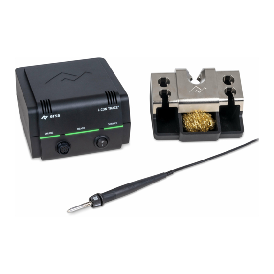
Commissioning control elements and connectors Fig. 4: Front and back view ONLINE LED Network cable connection Soldering iron socket Fuse compartment READY LED Type plate On/Off switch QR code of this soldering station SERVICE LED Optional Ethernet network card Fig. 5: Bottom side Release lever Reset key Ersa GmbH... -
Page 20: Preparing The Soldering Station To Be Switched On For The First Time
Commissioning Preparing the soldering station to be switched on for the first time Info: Store the soldering iron only in the central appropriate support, not in the side storage funnels of the soldering tips! (See Fig. 7) a) The Safety Notes listed in the chapter For your safety [} 5] must be observed. b) Make sure that the line voltage complies with the value specified on the type plate. - Page 21 Commissioning d) Insert the dry cleaner; Fig. 7 shows the recommended position. Fig. 8: Plugging in the soldering iron e) Fig. 8 left: Insert the plug of the soldering iron [1] into the soldering iron socket at the soldering station [2]. When doing so, align the plug anti-rotation device with the lower recess in the socket, see arrow.
-
Page 22: Switching On The Soldering Station For The First Time
Commissioning Switching on the soldering station for the first time CAUTION Risk of burns! The soldering iron gets hot immediately after it is switched on! Never touch the hot soldering tip or the hot heating element directly! CAUTION Risk of burns! The soldering station with soldering iron is factory preset to 360 °C (680 °F)! Even without a network connection or installing any software, the soldering iron can be heated by turning on the On/Off switch on the soldering station. -
Page 23: Switching Off
Commissioning Switching OFF: CAUTION Attention Risk of burns! After switching off, the soldering tip remains hot for a long time! a) Switch off the soldering station through the on/off switch [1] on the front of the device. Fig. 9: Switching off the soldering station ð... -
Page 24: Establishing A Wlan Connection Between The Soldering Station And A Network
WLAN network. – The PC that is used as a server must be compatible with the network. – The “Ersa TRACE” app is used to integrate an i-CON TRACE soldering station into the WLAN. Info: Alternatively, the soldering station can also be integrated into a LAN network. - Page 25 Commissioning CAUTION Risk of burns! The soldering iron gets hot immediately after it is switched on! Never touch the hot soldering tip or the hot heating element directly! CAUTION Risk of burns! The soldering station with soldering iron is factory preset to 360 °C (680 °F)! Even without a network connection or installing any software, the soldering iron can be heated by turning on the On/Off switch on the soldering station.
- Page 26 Commissioning The soldering station will now automatically connect to the server every time it is switched on. The steps for establishing a WLAN connection to the soldering station must be car- ried out again after resetting the soldering station. 3BA00252-01 | Rev. 1 Ersa GmbH...
-
Page 27: Establishing A Lan Connection Between The Soldering Station And A Network
Commissioning Establishing a LAN connection between the soldering station and a network This chapter describes the integration and operation of the soldering station in a LAN network. – The PC that is used as a server must have an Ethernet LAN connection. –... - Page 28 Commissioning Fig. 12: Inserting the optional Ethernet network card d) Press the Reset key to reset the soldering station. Read more about this in Chapter Resetting the soldering station with the reset key [} 40]. e) Connect the LAN cable to the Ethernet network card and connect it to the LAN. f) Make sure that the connection cables are never under strain! 5.9.1.1 Pulling out the optional Ethernet network card...
- Page 29 Commissioning Fig. 13: Pulling out the Ethernet network card e) Carefully pull out the network card [2] by the LAN cable. f) The next time the soldering station is switched on, press the Reset button to reset it. Read more about this in Chapter Resetting the soldering station with the reset key [} 40].
-
Page 30: Function Description
Function description Function description Information on the LED indicators ONLINE LED signals Blue The soldering station is waiting for the Bluetooth connec- tion to be established through the “Ersa TRACE” app for in- tegration into the WLAN network Yellow Network alright, no connection to the “Ersa TRACE Cockpit“ web app Green Network connection established... -
Page 31: Changing Soldering Tips
Function description Changing soldering tips The new 142 soldering tip series was developed for the soldering station i-CON ® TRACE . The “Ersa TRACE Cockpit” web app can use the QR code on each soldering tip to recognise the soldering tip and manage the work carried out with it. 6.2.1 Changing a soldering tip in the supporting stand Info: Place the soldering iron only with the soldering tip mounted and only in the... - Page 32 Function description ð The READY LED is pulsing blue, which means that the heating element is off. b) Alternatively, use the On/Off switch to turn off the soldering station. Storing a soldering tip Fig. 15: A soldering tip can be stored in four steps a) Figure 15 on the left: Insert the soldering iron all the way into the changeable funnel [1], then tilt the soldering iron slightly away from you [2].
- Page 33 Function description Picking up a soldering tip Fig. 16: A soldering tip can be picked up in four steps a) Figure 16 on the left: Insert the heating element all the way into the soldering tip [1], then turn the soldering iron clockwise as far as it will go [2]. b) Figure 16 on the right: Turn the soldering iron slightly towards you [3] and pull it out [4].
- Page 34 Function description 6.2.2 Manually replacing a soldering tip CAUTION Risk of burns! The soldering iron gets hot immediately after it is switched on! Never touch the hot soldering tip or the hot heating element directly! CAUTION Attention Risk of burns! After switching off, the soldering tip remains hot for a long time! Always touch only the knurled plastic part! ([2] in Figure 17) To prevent any material damage due to overheating, switch off the heating ele-...
- Page 35 Function description Replacing a soldering tip CAUTION Risk of burns! Allow the soldering iron to cool off until reaching a safe temperat- ure! Touching the knurled plastic component of the soldering tip is always at your own risk. If necessary allow the soldering tip to cool down completely before changing Fig. 19: Unlock [1] and pull out [2] the soldering tip Fig. 20: Remove the soldering tip Ersa GmbH...
- Page 36 Function description Fig. 21: Fit the soldering tip [1], overcome the spring force and lock the bayonet mount [2] a) To check the soldering tip for tight seating: Keep a correct distance between the knurled sleeve [2] and the soldering iron [3], as shown in Fig.
-
Page 37: Service And Maintenance
Service and maintenance Service and maintenance Error messages and error codes The “Ersa TRACE Cockpit” web app shows errors such as an error code with an info message. The SERVICE LED on the soldering station shows the error status. Read more about this in Chapter LED signals [SERVICE]. -
Page 38: Error Treatment
Service and maintenance Error treatment In case of faulty operation of the soldering station, check the following items: a) Soldering iron does not get hot. Is the soldering iron connected correctly to the soldering station? b) Soldering station remains off after switch-on / no line voltage? Correctly connect the mains cable to the soldering station and socket. - Page 39 Service and maintenance Fig. 23: Replacing the fuse b) Remove the fuse holder and replace the “0.8 A slow blowing” fuse for the 230 V variant, or the “1.6 A slow blowing” one for the 115 V variant in the holder. c) Re-install the fuse holder and close the compartment.
- Page 40 Service and maintenance Fig. 24: Replace the heating element ü Slide in the spare heating element. a) Align the groove of the heating element [1] with the marking in the soldering iron [2]. b) Align the heating element exactly parallel to the soldering iron. c) Gently push the heating element in carefully and slowly until it stops.
- Page 41 Service and maintenance Fig. 25: Reset button [12] on the underside of the device d) With the reset button pressed in, switch on the soldering station. e) When all 3 LEDs light up yellow, release the reset button. ð The soldering station has been reset to factory settings. f) Switch off the soldering station.
-
Page 42: Cleaning And Maintenance
Service and maintenance Cleaning and Maintenance Info: There are no user-serviceable parts inside the soldering station. CAUTION Danger of electric shock! Before cleaning, de-energise the soldering station by pulling out the mains plug! CAUTION Attention Risk of burns! After switching off, the soldering tip remains hot for a long time! Cleaning a) Occasionally clean the device with a soft, damp cloth. - Page 43 Service and maintenance b) If necessary, wipe the soldering tip with a damp sponge or by dipping the tip several times into the dry cleaning agent shortly before the soldering process. c) To achieve good electric and heat conductivity, the tip should be occasionally removed and the heating element cleaned with a brass brush.
- Page 44 Service and maintenance Defaults The following table shows the factory settings. After a reset with the reset key (see chap. Resetting the soldering station with the reset key [} 40]), the current settings are deleted and the factory settings restored. Parameter Value Target temperature (°C /°F) 360 / 680...
- Page 45 Spare/wear parts and accessories Spare/wear parts and accessories ® Electronic soldering station i-CON TRACE 220-240 V / 110-120 V, antistatic, complete with i-TOOL TRACE soldering iron, soldering tip 0142CDLF16 and sup- porting stand ® Electric soldering station i-CON TRACE 220-240 V / 110-120 V, anti-static Soldering iron i-TOOL TRACE, 24 V, 150 W, antistatic, with soldering tip 0142CDLF16 Supporting stands for i-TOOL TRACE, anti-static...
- Page 46 China Kurtz Ersa, Inc. Ersa France Ersa Shanghai usa@kurtzersa.com ke-france@kurtzersa.com info-esh@kurtzersa.com www.ersa.com www.kurtzersa.com www.ersa.com Mexico Asia Vietnam Kurtz Ersa, S.A. de C.V. Kurtz Ersa Asia Ltd. Kurtz Ersa Vietnam info-kmx@kurtzersa.com asia@kurtzersa.com Company Limited www.ersa.com www.ersa.com info-kev@kurtzersa.com www.ersa.com GLOBAL. AHEAD. SUSTAINABLE.
Need help?
Do you have a question about the i-CON TRACE and is the answer not in the manual?
Questions and answers