Table of Contents
Advertisement
Quick Links
Advertisement
Table of Contents

Related Manuals for Kurtz Ersa i-CON VARIO 2P


Summary of Contents for Kurtz Ersa i-CON VARIO 2P
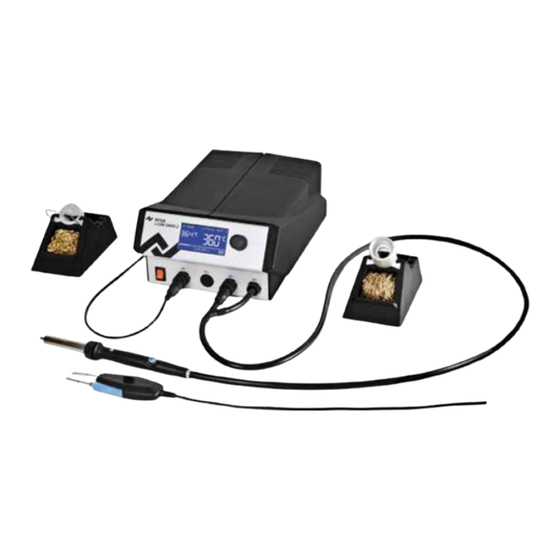
- Page 1 i‑CON VARIO 2 i‑CON VARIO 2P i‑CON VARIO 2HP i‑CON VARIO 2X Soldering & Desoldering Station Operating Instructions Ersa GmbH Leonhard-Karl-Str. 24 Phone +49 9342/800-0 97877 Wertheim/Germany Fax +49 9342/800-127 www.ersa.com service.tools@kurtzersa.de...
-
Page 2: Table Of Contents
Table of Contents Table of Contents 1. Introduction ..........................5 1.1 Supply unit ..........................5 2. Technical data..........................6 3. Concerning your safety ....................... 9 3.1 Explanations on pictograms and symbols .................. 9 3.2 Safety instructions ........................10 3.3 Intended use ..........................12 3.4 National and international regulations .................. - Page 3 Table of Contents 6.3 Parameter mode ........................27 6.3.1 i-SET TOOL ........................28 6.3.2 Target temperature ...................... 28 6.3.3 Min. temp. / Max. temp....................29 6.3.4 Calibration temperature ....................29 6.3.5 Setting the size of the hot air nozzle i-TOOL AIR S ............29 6.3.6 Tip offset ........................
- Page 4 Table of Contents 6.8.1 Changing the i-TOOL heating element ................43 6.8.2 Changing the i-TOOL AIR S heating element ..............43 6.8.3 Changing the CHIP TOOL heating element ..............43 6.8.4 Changing the CHIP TOOL VARIO heating element ............44 6.8.5 Replacing the X-TOOL VARIO heating head ..............
-
Page 5: Introduction
Introduction Introduction We would like to thank you for purchasing this high quality soldering station. The Ersa i‑CON VARIO 2 is a multi‑function soldering station for professional soldering and desoldering processes. It has been designed for applications in industrial production, repair operations and laboratory environments. Supply unit Up to two soldering and desoldering tools (hereafter referred to as “soldering tool”) can be connected to the supply unit and operated together. -
Page 6: Technical Data
Technical data Technical data Soldering station i‑CON VARIO 2 Designation Value Dimensions approx. 180 mm x 280 mm x 115 mm Weight Approx. 6 kg Voltage 220 – 240 VAC Mains frequency 50 Hz Fuse (slow blowing) 3.15 A Secondary voltage 24 VAC Maximum short‑term heating power 350 W... - Page 7 Technical data Soldering iron Tool AIR S Designation Value Operating voltage 24 VAC Maximum heat output 200 W Temperature range 50 °C – 550 °C Temperature sensor K-type thermocouple Air supply Blowing air up to 20 l/min, adjustable on the tool Weight (without power cable) Approx.
- Page 8 Technical data Soldering iron i‑TOOL HP Designation Value Operating voltage 24 VAC Heating power 250 W Heat‑up time Approx. 40 s to 380 °C Temperature range 150 – 450 °C Temperature measurement Ni-CrNi thermocouple Weight Approx. 110 g Design Antistatic Soldering iron TECH TOOL Designation Value...
-
Page 9: Concerning Your Safety
Concerning your safety Concerning your safety Ersa products are developed, manufactured and tested in compliance with general requirements concerning health and safety. However, residual risk do remain! You should therefore read this instruction manual before you start to operate the device for the first time. -
Page 10: Safety Instructions
Concerning your safety Safety instructions DANGER! Malfunctions of the device possible! Check all components before each use. Have damaged parts only repaired by a specialist or the manufacturer. If repairs are carried out inappropriately, the operator may become victim of accidents. Always use original Ersa spare parts for possible repairs. - Page 11 Concerning your safety CAUTION! Danger of poisoning by inhalation! Harmful fumes are produced during soldering. Ensure sufficient ventilation or extraction. Follow the relevant safety data sheets of the used solder paste and flux. WARNING! Dangerous electrical voltage! Protect the supply cables. Do not use the power supply cable to pull out the plug or to carry the device.
-
Page 12: Intended Use
Concerning your safety Intended use Thermal tools from Ersa must only be used for the processing of soft solder. However, if explicitly described in the operating instructions of the respective thermal tool, some thermal tools may, in exceptional cases, be used for the processing of plastic materials. In case of unintended use and tampering with the device, any warranty and liability claims of the buyer against the manufacturer will become null and void. -
Page 13: Transport, Storage, Waste Disposal
Transport, storage, waste disposal Transport, storage, waste disposal Transport and storage The i-CON VARIO 2 is delivered in a strong cardboard box. Please use only the original packaging for transportation and intermediate storage. Strictly avoid jerky movements, impacts or putting down of the i‑CON VARIO 2. -
Page 14: Commissioning
Order number Contents 0ICV2000A 0ICV2000AI 0ICV2000AC 0ICV2000AXV 0ICV2000HP 0ICV2000XV 0ICV2000XVI i-CON VARIO 2 0ICV203A i-CON VARIO 2P 0ICV203AP i-CON VARIO 2HP 0ICV203HP i-CON VARIO 2X 0ICV203X i-TOOL AIR S 0470ERJ i-TOOL 0100CDJ CHIP TOOL VARIO 0460MDJ... -
Page 15: Switching On The First Time
Commissioning Switching on the first time For safe and durable operation of the soldering tools you must strictly observe the following items: ■ Before switching on, make sure that the mains voltage complies with the value specified on the type plate. ■... - Page 16 Commissioning ■ Connect the mains supply cable with Rework heating plate and mains supply socket ② ■ Switch on the soldering station ③ Ersa i-CON VARIO 2 3BA00205 • 2022-06-15 • Rev. 6...
-
Page 17: Functional Description
Functional description Functional description Operation The soldering station is switched on/off by the switch on the front ① The soldering station is controlled via a rotary encoder with push‑button function (press). It is ② called i‑OP. The i‑OP allows the selection of desired functions or the change of values. Clockwise turning results in higher values and counter‑clockwise turning in lower values. -
Page 18: Microsd-Card
Functional description 6.2.1 microSD‑card The use of a microSD card allows to make firmware updates. For more information on using the mi- croSD card, please refer to the firmware update instructions. The firmware and the update instructions can be found at www.kurtzersa.com in section "i‑CON VARIO 2" under "Downloads". 6.2.1.1 Insert microSD‑card The station provides a port for a microSD‑card. -
Page 19: Working With The I-Tool Air S
Functional description 6.2.4 Working with the i‑TOOL AIR S The i‑CON VARIO 2 is equipped with an air supply, to be able to connect the hot‑air soldering tool i‑TOOL AIR S. In contrast to regular soldering tools, this tool transfers the required energy for soldering by means of hot air convection. - Page 20 Functional description Tips for operation and settings: It is recommended to maintain a sufficient distance between the soldering good and the soldering tool while working with the i-TOOL AIR S. It is depending on the used air quantity and temperature and should be about 1 – 5 mm. Operation Temperature range Air quantity...
-
Page 21: Working With The Chip Tool Vario
Functional description 6.2.5 Working with the CHIP TOOL VARIO The desoldering forceps CHIP TOOL VARIO is equipped with two very small, but powerful heating elements. Each side has a heating power of 40 W, and differences in tip geometry enable reliable removal of even the smallest SMT-components. -
Page 22: Working With The X-Tool Vario
Functional description 6.2.6 Working with the X‑TOOL VARIO* The X‑TOOL VARIO is a more sophisticated high‑performance desoldering iron with improved hand- piece. 6.2.6.1 Before first commissioning ■ Assemble the holder of the desoldering iron, as shown opposite. Switch off the control station. ■... -
Page 23: Desoldering With X-Tool Vario
Functional description Ersa desoldering tips are modelled on the meniscus of the solder joint so as to ensure optimal heat transfer. Select the internal diameter of the desoldering tip in such a way that a small annular clearance of about 0.1 to 0.2 mm is left between the connection to be desoldered and the exhaust duct, so as to be able to suction the solder residues. - Page 24 Functional description Removing/installing residual solder pots ■ Let the tool cool down to room temperature. ■ With a rotational movement, pull the residual solder pot out of the holder. ■ To re‑install the residual solder pot, press it back into the holder with a rotary motion until the edge of the container is level with the mark- ing on the handle.
-
Page 25: Working With The Vac Pen
Functional description 6.2.7 Working with the VAC PEN* The vacuum placer VAC PEN enables precise handling of SMT-components. In order to be able to connect the VAC PEN to the station the prefilter must be installed on the VAC tool socket. ■... -
Page 26: Working With The Heating Plate
Functional description 6.2.9 Working with the heating plate The heating plate is switched on as follows: ■ With the function [Heating plate] activated, you can switch on the heating plate in the working mode by double‑clicking the i‑OP. ■ The window appears for 2 seconds. -
Page 27: Parameter Mode
Functional description Parameter mode The following settings can be made in parameter mode: • Nominal temperature (150 – 450 °C / 302 – 842 °F) (i-TOOL AIR S 50 – 550°C/122 – 1020 °F) • Calibration temperature (−70 ... +50 °C/−126 ... +90 °F) •... -
Page 28: I-Set Tool
Functional description 6.3.1 i‑SET TOOL The i‑SET TOOL (optional) enables you to save the settings (including the password) of the station in the i‑SET TOOL and to write it back to the station. This way you can quickly transfer the basic settings to several stations. -
Page 29: Min. Temp. / Max. Temp
Functional description 6.3.3 Min. temp. / Max. temp. The Min. temp. and Max. temp. parameters determine the temperature range in which the tool’s temperature can be adjusted. The tool’s temperature can be changed directly in operating mode by turning i OP. This temperature can be reduced by adjusting the Min. -
Page 30: Tip Offset
Functional description 6.3.6 Tip offset Due to the different masses and geometric shapes of the soldering tips, their thermal characteristics are quite different. The tip offset serves the purpose of adapting the temperature measurement to the corresponding soldering tip used. The setting for the soldering tip used is made by entering a number. -
Page 31: Calibrating The I-Con Vario 2
Functional description 6.3.7 Calibrating the i‑CON VARIO 2 On the i‑CON VARIO 2 two calibration functions are available, which are tool‑dependent can be separately selected and adapted where necessary: • Tip offset function and • calibration function. The Tip offset function is not available for a connected i‑TOOL. The following procedure is required to correctly calibrate the soldering station: First one must enter the tip used on the soldering tool (see section 6.3.6 [Tip offset]). -
Page 32: Energy
Functional description 6.3.9 Energy This function enables the user to influence the regulating behavior of the station, whereby the heating and after heating characteristic of the station can be adapted to the actual application. Three settings [high], [med.], and [low] are possible for i‑TOOL, TECH TOOL, CHIP TOOL VARIO and i‑TOOL AIR S. -
Page 33: Configuration Mode
Functional description Configuration mode To enter the configuration mode press and hold the i‑OP for 2 seconds when switching on the i‑CON VARIO 2. By turning and pressing the whole station can be configured or reset to factory settings. In configuration mode the following settings can be adapted for the station: •... -
Page 34: Process Alarm
Functional description 6.4.2 Process alarm Once the actual temperature leaves the temperature window, a single audible signal will sound. Once the actual temperature returns to temperature window, a double audible signal will sound. Factory setting: [off]. 6.4.3 Password protection The data of the station can be protected by a 4‑digit (0001‑9999) password. -
Page 35: Changing The Password
Functional description The second display [Password activation] appears: ■ Enter the password once again and press i‑OP to confirm your entry. The display [Configuration] appears with the message [PASSWORD LOCK IS ACTIVE]. The station is now protected. 6.4.5 Changing the password The password is set in configuration mode. -
Page 36: Temperature Unit
Functional description 6.4.7 Temperature unit Here you can choose the desired temperature units Degree Celcius (°C) or Fahrenheit (°F). Factory setting: “°C” 6.4.8 Language selection Here you can choose the desired language for the menus of the i‑CON VARIO 2. Factory setting: “English” 6.4.9 Adjustable shut‑down function (idle state) The adjustable shut‑down function (Idle state) serves the purpose of... -
Page 37: Heating Plate
Functional description 6.4.10 Heating plate You can use the soldering station to control the infrared heating plate 0IRHP100A. The following accessories are needed: • Control cable from soldering station to the infrared heating plate 0IRHP100A • Y‑control cable given that the soldering smoke extractor and the infrared heating plate 0IRHP100A are to be controlled together. -
Page 38: Factory Settings ("Default")
Functional description The VAC PEN Mode is deactivated. ① The VAC PEN Mode is activated. ② ■ Quit the configuration menu. VAC PEN and X-TOOL VARIO can not be operated simultaneously. Factory settings (“Default”) The following list shows the settings with which the station has been programmed in the factory. These settings can be restored via the “Default function”... -
Page 39: Contrast
Functional description Contrast Please proceed as follows to adapt the display contrast to your working environment: ■ Switch on the station and rotate the i‑OP immediately. This activates the contrast mode: The buzzer sounds to signalize that the contrast mode is active. ■... -
Page 40: Changing Soldering Tips
Functional description Changing soldering tips Soldering tips must be changed when: • The size of the soldering tip does not match the soldering joint (current tip too big / too small). • The soldering tip is worn or damaged (pitting corrosion, tip can no longer be wetted, mechanical damage). -
Page 41: Replacing The Soldering Tip In The Soldering Tip Fastening
Functional description ■ Push the new soldering tip with the soldering tip fastening on to the heating element. Before this, check whether the soldering tip has fully engaged in the holding cage. ■ Turn the knurled nut clockwise to tighten the soldering tip. ■... -
Page 42: Changing Desoldering Tips Of X-Tool Vario
Functional description 6.7.3 Changing desoldering tips of X‑TOOL VARIO A desoldering tip can be changed using the tip holder fitted to the supporting stand, with the included tip changing pliers (no. 3N597), or with the VARIO TOOL (no. E074600). Tip change using a tip holder: ■... -
Page 43: Changing A Heating Element
Functional description Changing a heating element Before changing a heating element: ■ Switch off the station and allow the soldering tip to cool down. Then remove the soldering tip as described above. ATTENTION! Risk of burning! Allow the unit to cool to a safe temperature. 6.8.1 Changing the i‑TOOL heating element ■... -
Page 44: Changing The Chip Tool Vario Heating Element
Functional description 6.8.4 Changing the CHIP TOOL VARIO heating element On the CHIP TOOL VARIO a desoldering tip always consists of a heating element and a soldering tip. A pair of desoldering tips should never be separated during use. When aligning the tips with each other, the anti‑turn locking device must be always disengaged. -
Page 45: Changing The Prefilter
Functional description Use the brush only to clean the heating element, so as to avoid transferring any tin from the soldering tips. ■ Open the bayonet lock of the tip by twisting and pulling. ■ Remove the tip retainer and the soldering tip. ■... -
Page 46: Sensitive Components
Functional description 6.10 Sensitive components Some components may suffer damage when being exposed to electrostatic discharge (please follow the warnings on the packages or ask the manufacturer or supplier). An ESD‑safe (ESD = Electrostatic Discharge) workplace provides sufficient protection for such components. The soldering station can be easily integrated into such an environment. -
Page 47: Error Diagnosis And Remedy
Error diagnosis and remedy Error diagnosis and remedy General errors If the soldering station does not operate as expected, check the following items: • Is the mains voltage present? Correctly connect the mains lead to the device and socket. • Is the fuse defect? The fuse can be found at the rear side of the device in the mains connecting socket. -
Page 48: I-Tool Thermocouple
Error diagnosis and remedy 7.3.2 i‑TOOL thermocouple Between measuring points you should be able to measure a volume resistance of approx. 2 ③ ④ to 3 Ohm. In case of a higher volume resistance the heating element must be replaced. When measuring on the plug of the i‑TOOL (heating element must be installed in the soldering iron), the resistance measured between the two measuring points should be approx. -
Page 49: Continuity Check For X-Tool Vario
Error diagnosis and remedy The volume resistance between the measuring points should be 2.3 Ω ± 10%. If this is not ① ② true, you must replace the heating element. If you do not reach the specified values during the previously described test you should return the tool to the Ersa Service for heating element replacement. -
Page 50: I-Tool Hp Heating Element
Error diagnosis and remedy 7.7.1 i‑TOOL HP Heating element Between measuring point a resistance of about 1.7 to 2 ohms should be measurable (at ① ② cool soldering iron). On interruption the heating element has to be renewed. ( = potential equaliza- ⑦... -
Page 51: Error Messages
Error diagnosis and remedy Error Messages The i‑CON VARIO 2 carries out automatic error diagnostics. The result of a diagnosis is displayed as an error code: The triangular pictogram thereby appears in the display of the soldering station. The error ①... -
Page 52: Maintenance And Cleaning
Maintenance and cleaning Maintenance and cleaning Important service work The following points must be complied with to achieve a long lifetime of the station. ■ Always make sure that the soldering and desoldering tips are tin coated. A continuously cleaned soldering tip will become passive after a short while. If you always leave a small amount of solder on the soldering tip after soldering, you will prolong the lifetime many times over. -
Page 53: Spare Parts, Accessories
Spare parts, accessories Spare parts, accessories Spare parts, accessories Designation Order‑No. Soldering iron i‑TOOL, 24 V, 150 W, antistatic with tip 0102CDLF16 0100CDJ i-TOOL AIR S 0470ERJ i-TOOL AIR S 0470BRJ Desoldering tip CHIP TOOL, 24 V, 2 x 20 W, antistatic, with tips 422 0450MDJ CHIP TOOL VARIO 0460MDJ... - Page 54 Spare parts, accessories Spare parts, accessories Designation Order‑No. i-SET TOOL 0103IST Knurled nut for i-TIPS 3N497 Covering sleeve for i-TIPS 3N539 Soldering tip fastening for i‑TIPS, complete, black 3IT1040-00 Heating element for i‑TOOL 010102J Viscose sponge for holder 0003B Cleaning brush with brass bristles 3TZ00051 Dry sponge with receptacle for 0A39 –...
-
Page 55: Desoldering Tips Chip Tool Vario (One Pair Each)
Spare parts, accessories Desoldering tips CHIP TOOL VARIO (one pair each) Spare parts, accessories Designation Order‑No. Chisel shaped, 0.7 mm, angled 0462MDLF007 Chisel shaped, 1.5 mm, angled 0462MDLF015 Pen pointed, 0.2 mm, angled 0462SDLF002 Pen pointed 0.5 mm 0462PDLF005 Chisel shaped 1.0 mm 0462CDLF010 Chisel shaped 1.8 mm 0462CDLF018... -
Page 56: Warranty
Warranty Warranty © 6/2022, Ersa GmbH · 3BA00205 Rev. 6 Heating elements and soldering or desoldering tips are treated as wearing parts, and are therefore not subject to the warranty. Any return of goods must be accompanied by a written description of the material or construction fault that has occurred as well as a confirmed purchase invoice. - Page 57 Warranty Ersa i-CON VARIO 2 3BA00205 • 2022-06-15 • Rev. 6...
- Page 58 Phone +852 2331 2232 www.ersa.com asia@kurtzersa.com Mexico www.ersa.com Ersa France Kurtz Ersa México, S.A. de C.V. Division de Kurtz France S.A.R.L Av. Lopez Mateos Sur Núm. 1450 Int. 7 China 15 rue de la Sucharde Col. Las Amapas (Plaza las Villas)
Need help?
Do you have a question about the i-CON VARIO 2P and is the answer not in the manual?
Questions and answers