Table of Contents
Advertisement
Quick Links
Advertisement
Table of Contents

Related Manuals for Kurtz Ersa i-CON 1 MK2


Summary of Contents for Kurtz Ersa i-CON 1 MK2
- Page 1 Operating instructions i-CON 1 MK2 Ersa soldering station...
-
Page 2: Table Of Contents
Contents 1. For your safety ....................... 5 Intended use ......................6 National and international regulations..............8 2. Technical data ........................ 9 3. Transport, storage and disposal ................. 11 4. Commissioning ......................12 Before starting operation ..................12 4.2 Switching on for the first time ................13 5. - Page 3 Contents 5.3.4 Tip offset ....................25 5.3.5 i-CON 1 Calibrating ................. 25 5.3.6 Calibration temperature ................26 5.3.7 Power Level .................... 26 5.3.8 Standby-Time ..................27 5.3.9 Standby-Temperature ................27 5.4 Configuration mode ....................28 5.4.1 Temperature window ................29 5.4.2 Process alarm ..................29 5.4.3 Password lock ..................
- Page 4 Contents 5.4.9 Two fixed temperatures ................37 5.4.9.1 Activating function ..............37 5.5 Factory settings (“default”) ................... 38 Contrast ....................... 39 Replacing the soldering tip ................... 40 5.8 Changing the Heating Element ................42 5.9 Sensitive components ..................43 6. Error diagnosis and remedy ..................44 Error Messages ....................45 7.
-
Page 5: For Your Safety
For your safety For your safety Ersa products are developed, produced and tested in compliance with the basic safety requirements. Nevertheless, residual risks still exist! For this reason, please read these operating instructions before you operate your device for the first time. It helps you to become familiar with the device‘s functions and to use them optimally. Please store these operating instructions at a place which is always accessible to all users! 3BA00268-1 • Rev. 1... -
Page 6: Intended Use
For your safety Intended use Ersa heating tools may only be used for the processing of soft solder. In special cases, however, if stated explicitly in the operating manual of the respective tool, some tools can also be used to work plastics. If the tool is not used as intended or tampered with, the manufacturer cannot be held liable for any warranty and liability claims on part of the purchaser. Attention! Check all components before use. Have any damaged parts repaired by a specialist or the manufacturer. Incorrectly per- formed repairs represent a risk of accidents for the user. Always use genuine Ersa spare parts for any repairs. Attention! Heating tools get hot. Before heating up the device, check that the tool insert (e.g. soldering tip, modelling insert, etc.) is cor- rectly connected to the heating tool. Do not allow the hot tool insert to touch your skin, your hair or any materials which are heat-sensitive and flammable. Always work on a base with adequate heat-resistant properties. - Page 7 For your safety Attention! Never leave your hot heating tool unattended. Remember that the tool insert needs a certain amount of time to cool down to a safe temperature even after you have switched the device off. Caution! Keep your workplace tidy. An untidy workplace increases the risk of accidents. Attention! Lead alloyed solders are toxic. Solders containing lead are toxic if they enter human body. For this reason, it is strictly forbidden to eat, drink or smoke. By equal measure, you should thoroughly wash your hands after working with lead alloyed solder. Attention! Dispose of waste solder in a responsible fashion. Comply with your local authority’s waste disposal regulations when disposing of the by-products of your soldering work.
-
Page 8: National And International Regulations
For your safety Warning! Protect connection cables. Do not use the connection cable to pull out the plug or as a means of carrying the device. Make sure that connection cables are not exposed to heat and do not come into contact with oil or sharp edges. Damaged connection cables represent a potential cause of fire, short-circuits and electric shocks. Damaged connecting cables can cause fire, short circuits, and electric shock, consequently they must be replaced immediately. Attention! Take account of ambient conditions. Protect your device against all liquids and moisture. Failure to do this represents a risk of fire or electric shocks. Caution! Look after your heating tool. Always keep your Ersa product in a safe, dry place out of the reach of children. Pay attention to any maintenance requirements. Check your device at regular intervals. -
Page 9: Technical Data
Technical data Technical data Soldering station i-CON 1 Description Value Unit Mains voltage 220-240 Mains frequency 50-60 Fuse (slow-blow) Mains voltage 110-120 Mains frequency 50-60 Fuse (slow-blow) Secondary voltage Maximum short-term heating power Mean heating power Safety class Permissable ambient temperature 0-40 °C Temperature range (stepless) 150-450 °C 300-842 °F Temperature regulation (at idle) <... - Page 10 Technical data Soldering station i-CON 1 Description Value Unit Anti-static surface, especially suitable for use in ESD areas. Option: Serial interface for controlling the EASY ARM soldering smoke extractor and the 0IRHP100A heating plate In accordance with MIL-SPEC/ESA-standard VDE*, EMV-tested *A public safety testing company located in Germany. Similar in operation to its Conformity United States counterpart, UL.
-
Page 11: Transport, Storage And Disposal
Transport, storage and disposal Transport, storage and disposal The i-CON 1 are each delivered in a stable box enclosure. Only use the original packaging for transport and interim storage of the systems. Do not move jerky or drop the i-CON 1. The i-CON 1 must be protected from weather influences such as rain, fog, sea air, etc. If the units will be stored for a longer period of time under humid conditions, then the i-CON 1 must be packed air-tight with desiccating agents in the enclosure. Damages due to improper transport and storage are not covered by the guarantee. Disposal Notice in accordance with directive 2012/19/EC of the Euro- pean Parliament and the council of July 4, 2012 on Waste Electrical and Electronic Equipment (WEEE). Products labelled with the symbol of the crossed out wheeled bin must not be disposed of with unsorted municipal waste. For this purpose, the local authorities have set up collecting points. Please ask your municipality which possibilities are offered for the separate collection of WEEE. This way, you make your contribution to the reuse or other forms of use of WEEE to protect our environment and health. -
Page 12: Commissioning
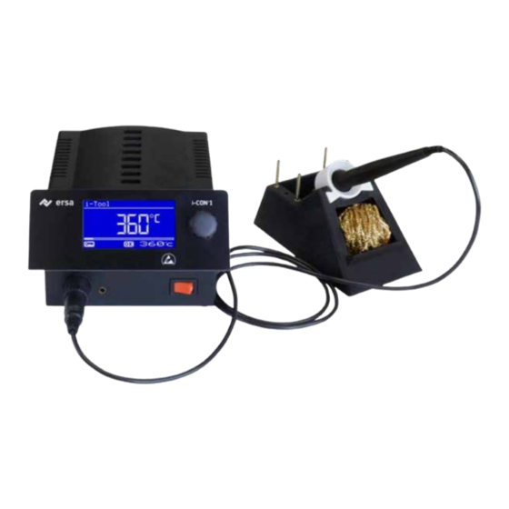
Commissioning Commissioning Before starting operation Please check the contents of the packaging for completeness. For more information read the chapter on [Replacement parts, accessories]! Should the listed compo- nents be damaged or incomplete, then please contact your supplier. The package consists of: • Electronic station i-CON 1 a • Soldering iron i-TOOL with soldering tip b • Storage stand with drying sponge c • Power supply cord • Operating Instructions Should the listed components be damaged, then please contact your supplier. -
Page 13: Switching On For The First Time
Commissioning Switching on for the first time Be sure to do the following to ensure the safe and long-lasting operation of the sol- dering tool: ■ Check whether the supply voltage matches the value stated on the rating plate. ■ Switch off the soldering station with the power switch a. ■ Check the right fit of the soldering tip. ■ Connect the soldering tool with the control station b and put the sol- dering iron in the holder. -
Page 14: Functional Description
Functional description Functional description Operation The soldering station is switched on and off by the mains switch on the front side a. The soldering station is controlled via a rotary encoder b with pushbutton function. It is called i-OP. The i-OP makes it possible to select desired functions or to change values. Clockwise turning results in higher values and counter-clockwise turning in lower values. Slow turning effects change in increments of one. Quick turning changes the selected values in increments of 10/50/100 (depending on the corre- sponding parameter). The i-OP has an additional pushbutton function. Via this pushbutton function (push- ing), the selected parameters and values are confirmed and become effective for the station. All setting steps and measured values are displayed in plain text in a clearly structured display window, which is simply referred to as “Display”. 3BA00268-1 • Rev. 1... -
Page 15: The Work Mode
Functional description The Work mode After the station has been switched on, the switch-on dialog is displayed for approx. 2 seconds. This dialog shows the station name a and the software version b of the i-CON 1. The station will then automatically change to work mode with the pa- rameters: • actual value c • set value and possibly standby status d • connected soldering tool (i-TOOL in our example) e • password lock active (KEY-symbol) f In the work mode, the soldering tip temperature can be directly changed by turning the i-OP. Confirm this by pushing the i-OP. Read more about this in the section - [Working with two fixed temperatures]. If the password lock is activated, the set value can only be changed via the parameter mode. The password is needed. -
Page 16: Setting Temperature Setting Of The Optional Heating Plate
Functional description 5.2.1 Setting temperature setting of the optional heating plate This function can only be vouched for when the soldering station is equipped with a serial interface (option). You can then use the soldering station to control the infra- red heating plate of the 0IRHP100A rework system. Read more on this in the sec- tion [Configuration Mode]. ■ Click the i-OP 3-times one after the other in the working mode. The adjoining display appears. ■ Set the desired temperature setting between [0] and [6] by turning the i-OP. The heating plate can be operated with 6 temperature settings. Set- ting [0]: the heating plate is witched off; Setting [1]: lowest heat output; Setting [6] maximum heat output. The factory setting is [0]. ■... -
Page 17: Working With The Optional Heating Plate
Functional description 5.2.2 Working with the optional heating plate The heating plate is switched on as follows: ■ With the function [Heating plate] activated, you can switch on the heat- ing plate in the working mode by double-clicking the i-OP. ■ The a window appears for 2 seconds. The b symbol signals that fact that the heating plate is working. The c display shows the set tem- perature setting. The heating plate is switched off as follows: ■... -
Page 18: Output Values Of The Heating Plate
Functional description 5.2.2.1 Output values of the heating plate To stop the heating plate overheating, the maximum temperature is limited to 300 °C (Temperature setting 6). The following characteristic shows the end temperatures of the heating plate at the various temperature settings. • Horizontal (x): set temperature setting • Vertical (T): temperature after 10 minutes of heating (°C) 3BA00268-1 • Rev. 1... -
Page 19: Working With Two Fixed Temperatures (Nominal Temperatures)
Functional description 5.2.3 Working with two fixed temperatures (nominal temperatures) This function allows you to save two fixed temperatures in the soldering station. When required, these temperatures can be easily and rapidly retrieved. Read through the [Configuration Mode] section on how to activate this function. Read through the [Parameter Mode] section on how to set the temperatures. Once you have carried out these two steps, then you can change between the set tempera- tures. • Two temperature values then appear in the left-hand half of the dis- play in the working mode. ■ Select the desired temperature by pressing the i-OP. The momentarily set temperature is shown on the display with a light background. When the set temperature is obtained, [OK] appears in the lower section of the display 3BA00268-1 • Rev. 1... -
Page 20: Parameter Mode
Functional description Parameter mode The following settings can be made in parameter mode: • Nominal temperature (150 - 450 °C / 302 - 842 °F) • Calibration temperature (−70…+50 °C / −126…+90 °F) • Tip offset (without function) • Energy function (3 stages) • Standby-Time (0 - 60 min) • Standby-Temperature (150 - 300 °C). Please proceed as follows to activate the parameter mode: ■ Press the i-OP and keep pressed for 2 seconds. The parameter mode is now activated. The desired parameter is selected by turning on the i-OP. For the selected parameter a, a help text b is displayed in the last line which gives additional explanations or numerical ranges. - Page 21 Functional description Proceed as follows in order to change a parameter value: ■ Press the i-OP and keep it pressed for 2 seconds to open the param- eter mode. ■ Select the desired parameter by turning the i-OP. ■ Press the i-OP to activate the cursor, pressing the i-OP subsequently de-activates the cursor. With the cursor activated, turning the i-OP accordingly changes the value of the parameter. 3BA00268-1 • Rev. 1...
-
Page 22: I-Set Tool
Functional description 5.3.1 i-SET TOOL With the i-SET TOOL (option) it is possible to save the settings (including pass- word) of the station. Also you can write back the saved settings into the station. This way, the basic settings can be transferred quickly to several soldering stations. Please observe the i-SET TOOL´s manual for this purpose. How to use the i-SET TOOL: ■ Disconnect the soldering tool from the soldering station and connect the i-SET TOOL. ■ Turn the i-OP and select the following: Upload: The data of the station is written into the i-SET TOOL. -
Page 23: Set Temperature
Functional description 5.3.2 Set temperature The set temperature is the desired soldering tip temperature. In the work mode, the soldering tip temperature can be directly changed by turning the i-OP. Confirm this by pushing the i-OP. 5.3.2.1 Setting two nominal temperatures (fixed temperatures) You can set a second nominal temperature. • Activating the [Fixed temperature] function in the [Configuration) mode is followed by two temperature values appearing in the left-hand half of the display in the working mode. ■ Select the desired temperature by pressing the i-OP. ■ Press the i-OP and keep it pressed for 2 seconds to open the param- eter mode. ■ Select the [Nominal temp.] parameter by turning the i-OP. ■ Activate the cursor by pressing the i-OP, set the desired temperature. ■ End the parameter mode. You have now set the first fixed temperature. ■ Select the second temperature by pressing the i-OP in the working mode and set in the parameter mode as described above. 3BA00268-1 • Rev. 1... -
Page 24: Calibration Temperature
Functional description 5.3.3 Calibration temperature Use this function to calibrate the soldering tip temperature. It makes it possible to adjust the display value and actual tip temperature. The adjustable calibration range is −70...+50 °C / −126...+90 °F. A description is given in Chapter [i-CON 1 Calibrating] on how to exactly proceed with the calibration. If you do not have a corresponding measuring unit for this measure- ment, please enter “0” into this parameter field. 3BA00268-1 • Rev. 1... -
Page 25: Tip Offset
Functional description 5.3.4 Tip offset Without function. 5.3.5 i-CON 1 Calibrating By using the calibrating temperature, the actual tip temperature is brought into exact conformity with the temperature displayed. Read more on this in the Section [Cali- brating temperature]. The following procedure must be adhered to when undertak- ing calibration: ■ Entering the desired nominal temperature [Nominal temperature] chapter. ■ Setting the calibrating temperature [Establishing calibrating temperature] chapter. 3BA00268-1 • Rev. 1... -
Page 26: Calibration Temperature
Functional description 5.3.6 Calibration temperature ■ Determine the soldering tip temperature with a calibrated measuring device (e.g. Ersa DTM 110). ■ Compare the two displayed values of i-CON 1 and the measuring de- vice. ■ Calculate the temperature difference: ∆T = T – T i-CON 1 measuring device ■ Set the calculated temperature difference ∆T (with algebraic sign via the rotary motion at the i-OP) in the menu item [Calibrate]. Quiet air conditions are important for the prevention of measurement errors. 5.3.7 Power Level This function enables the user to influence the regulating behavior of the station, whereby the heating and after heating behavior of the station can be matched to the actual application. Three settings are possible: [high], [med.] and [low]. • [Low]: Minimum post-heating characteristics. For soldering works with low heat demand. • [Med.]: Increased post-heating characteristics. For soldering works with increased heat demand. • [High]: Maximum post-heating characteristics. For soldering works with High very high heat demand. -
Page 27: Standby-Time
Functional description 5.3.8 Standby-Time The standby period is the time from the last work with the soldering tool to the point when the standby temperature is activated. The setting range is between 20 sec- onds and 60 minutes. The input [0] deactivates the standby function. For small soldering points or soldering works which are performed with very little motion, a sufficiently high standby-time should be se- lected. Otherwise the standby-function may lower the temperature already during the soldering process! As a measure to save energy and to prolong the lifetime of soldering tip and heater you can automatically trigger an idle state for the sol- dering tool. Please read section [Adjustable shut-down function (idle state)]. 5.3.9 Standby-Temperature This is the soldering tip temperature during work breaks. It is automatically activated when the standby-time has elapsed. When the temperature is decreased, power is saved and the service life of tip and heating element is increased. Reheating to standby temperature is accomplished either by moving the i-TOOL or by pressing / turning on the i-OP. 3BA00268-1 •... -
Page 28: Configuration Mode
Functional description Configuration mode In the configuration mode, the following settings are possible: • Temperature window (monitoring) • Device number • process alarm (acoustic temp. monitoring) • Idle state • Password • Temperature unit • Activating the heating plate • Activating the second fixed temperature • Language selection of the station To reach the configuration mode, keep the i-OP pushed for 2 seconds when you switch on the i-CON 1. 3BA00268-1 • Rev. 1... -
Page 29: Temperature Window
Functional description ■ turn the i-OP to select the menu option, then press: • [CHANGE] opens the menu [Configuration] • [ABORT] aborts the process • [DEFAULT] restores the factory settings. If the password lock is active, the soldering station cannot be reset to its delivery status (default) without the password. 5.4.1 Temperature window For the connected soldering tool a temperature window with an upper and lower range can be defined. If the actual temperature is within this window, the work dialog displays an “OK”. Factory setting: ±20 °C (68 °F). 5.4.2 Process alarm Without function. 3BA00268-1 • Rev. 1... -
Page 30: Password Lock
Functional description 5.4.3 Password lock The data of the station can be protected by a 4-digit password (0001-9999). This way, settings/changes can be prevented. The station does not come with activated password lock; this is indicated by “0000” in the password input field. The symbol a signalizes that the station is protected. Factory setting: [0000] = un- locked. Please memorize your selected password thoroughly or note it down at a safe spot. Only Ersa can deactivate a forgotten password. If you have an i-SET TOOL with the saved factory settings, you can also unlock the station on your own. 5.4.3.1 Setting the password Proceed as follows in order to activate the [password] function: ■... - Page 31 Functional description ■ Confirm your input by pushing the i-OP. The first [Password activation] image is displayed: Either ■ Select the [ABORT] item to quit the process. The password lock will not be activated in this case. ■ Note down the adjusted password, select the [>>>] item (continue), confirm by pushing the i-OP. The second [Password activation] image is displayed: ■ Enter your password again and Confirm your input by pushing the i-OP. The [Configuration] image with the message [PASSWORD LOCK IS ACTIVE!] is displayed. The station is now protected. 3BA00268-1 • Rev. 1...
-
Page 32: Changing The Password
Functional description 5.4.3.2 Changing the password The password is set in the configuration mode. If a password has already been set, the code is displayed as asterisk. If the user wants to change a password, the active password lock must first be re- voked by entering the current password. After the correct input, the new password can be set. If the numerical entry has been completed with the PUSH-function, a note is displayed indicating that the password lock is activated. The purpose of this note is to once more indicate the significance of this function to the operator. If the function is canceled, the previous state is maintained. If the operator continues the dialog [>>>], the password must be repeated for acti- vation. If the password has been repeated correctly, the station is protected by the code. If the code has been entered incorrectly, a note is displayed and the previous state is maintained. -
Page 33: Forgotten Password
Functional description 5.4.3.4 Forgotten password If you have forgotten your password, it can only be de-activated by Ersa Service. In such a case, please refer to the company Ersa, indicating your address, name, in- voice and serial number of the soldering station (see type plate). The password lock may also be de-activated with the i-SET TOOL. Please observe the corresponding hint at section [Password lock] to this purpose! 5.4.4 Temperature unit Here, the desired temperature unit, degree Celsius (°C) or Fahrenheit (°F), can be selected. Factory setting: “°C” Caution! When the temperature unit is changed, a setup mode is carried out. During this time (approx. 5 sec.), the station must not be switched off. 5.4.5 Language selection Here, the desired language for the menu navigation of the i-CON 1 can be selected. Factory setting: “English”. 3BA00268-1 • Rev. 1... -
Page 34: Adjustable Shut-Down Function (Idle State)
Functional description 5.4.6 Adjustable shut-down function (idle state) The adjustable shut-down function (idle state) serves the purpose of energy saving and prolonging the lifetime of soldering tip and heater. In idle state the tools cool down to room temperature. The bottom line in the display then shows the text [Shut Down]. You can end the idle state at any time by actuating the i-OP. Please proceed as follows to activate the function [Shut Down]: ■ Open the configuration mode and choose the option [Shut Down]. ■ Activate the menu [Shut Down] by turning the i-OP. ■ Press the i-OP to activate the cursor, press the i-OP again de-acti- vates the cursor ■ Enter the desired time from [010] to [240] minutes by turning the i-OP accordingly. The input [000] deactivates the function [Shut Down]. If the cursor is activated, turning the i-OP changes the value of the parameter accordingly. The set time starts to run, only after the tool is in [Standby]. If the tool is still not used during this time, idle state is activated after this time has expired. -
Page 35: Device Number
Functional description 5.4.7 Device number This function is only required, if the i-CON 1 is equipped with a serial interface (Op- tion). An unambiguous device number must be assigned for identification, to enable the PC to correctly allocate the connected station. Please proceed as follows to set the [Unit number]: ■ Open the configuration mode and choose the option [Unit number]. ■ Activate the menu [Unit number] by turning the i-OP. ■ Press the i-OP to activate the cursor, press the i-OP again de-acti- vates the cursor. ■ Enter the desired number from [01] to [32] by turning the i-OP accord- ingly. If the cursor is activated, turning the i-OP changes the value of the parameter accordingly. Details for correct assignment of device num- bers can be found in the documentation for the serial interface. -
Page 36: Heating Plate (Option)
Functional description 5.4.8 Heating plate (option) This function can only be vouched for when the soldering station is equipped with a serial interface (Option). You can then use the soldering station to control the infra- red heating plate 0IRHP100A (0IRHP100A-03) of the rework system. The following accessories are needed: • Control cable from soldering station to 0IRHP100A • Y-control cables given that the soldering smoke extractor and the 0IRHP100A are to be controlled together. 5.4.8.1 Connecting heating plate to soldering station ■... -
Page 37: Two Fixed Temperatures
Functional description 5.4.9 Two fixed temperatures This function allows you to determine two soldering tip temperatures and save them in the soldering station. You can retrieve these temperatures at any time. 5.4.9.1 Activating function ■ Select the menu [Fixed temperature] in the configuration mode by turning the i-OP. ■ Activate the cursor by pressing the i-OP. ■ Activate the function by turning the i-OP. The adjoining display appears. ■ Terminate the configuration menu. Information on working with two fixed temperatures can be found in the chapter [Working mode]. 3BA00268-1 •... -
Page 38: Factory Settings ("Default")
Functional description Factory settings (“default”) The following lists shows the settings with which the station was programmed in our works. These settings can be restored via the “default function” in the “Configura- tion” mode. The only exception is the setting of the password which is not deleted via the default function. Configuration mode Parameter Settings ↑ Tempwindow 20 °C ↓ Tempwindow 20 °C Shut down Unit number Heating plate Process alarm Password 0000 (is not deleted via the default function) Unit °C Language Parameter mode Parameter Settings Tempset (°C) Calibrate (°C) Tip-Offset Power level Medium Standby-Time (min) -
Page 39: Contrast
Functional description Contrast Follow these steps to adjust the contrast of the display to the respective work envi- ronment: ■ Switch on the station and rotate the i-OP immediately. This activates the [Contrast] mode. 0,5 s ■ Adjust the desired contrast by turning the i-OP. ■ Confirm your input by pushing the i-OP. 3BA00268-1 • Rev. 1... -
Page 40: Replacing The Soldering Tip
Functional description Replacing the soldering tip Replace the soldering tip when it is worn. ■ To prevent any material damage due to overheating, switch off the heating element or the soldering station before each soldering tip re- placement! ■ To prevent any material damage due to overheating, never operate the soldering iron without the soldering tip! Attention! Burn hazard! After switching off, the soldering tip remains hot for a long time! Always touch only the knurled plastic part When the tip has cooled off, proceed as follows: ... - Page 41 Functional description ■ Fit the soldering tip a, overcome the spring force and lock the bayo- net mount [2]. ■ To check the soldering tip for tight seating: Keep a correct distance between the knurled sleeve b and the sol- dering iron c, as shown in figure on the left. The bayonet mount of the knurled sleeve is completely locked. The display panels a do not touch the knurled sleeve b. 3BA00268-1 •...
-
Page 42: Changing The Heating Element
Functional description Changing the Heating Element Attention! Burn hazard! Only change the heating element when both the soldering tip and the heating element are cold! Before changing the heating element, switch off the soldering station and allow the soldering tip and the heating element to cool down! ■ Remove the soldering tip. ■ Pull the heating element out by hand. ■ Slide in the spare heating element. ■ Align the groove of the heating element a with the marking in the sol- dering iron b . ■ Align the heating element exactly parallel to the soldering iron. ■ Gently push the heating element in carefully and slowly until it stops. If the heating element cannot slide in easily, do not press with greater force, but reposition it! ■ Re-install the soldering tip. 3BA00268-1 •... -
Page 43: Sensitive Components
Functional description Sensitive components Many components may be damaged by electrostatic discharge (please observe the warnings on the packaging or ask the manufacturer or supplier). These components can be protected by an ESD-secure workplace (ESD = electrostatic discharge). The soldering station can be easily integrated into such an environment. The soldering tip can be connected at high resistance (220 kΩ) to the conductive workbase via the potential equalization jack (1). The soldering station has complete antistatic protection and also meets the require- ments of the American military standard. The soldering tips are default hard grounded. *Hard grounded in accordance with military and ESA standard. 3BA00268-1 • Rev. 1... -
Page 44: Error Diagnosis And Remedy
Error diagnosis and remedy Error diagnosis and remedy If the soldering station does not operate as expected, check the following items: • Is main voltage present? Correctly connect the mains lead to the de- vice and socket. • Is the fuse defect? The fuse can be found at the rear side of the de- vice in the mains connecting socket. • Note that a defective fuse may also indicate a deeper cause of error. Simply changing the fuse therefore generally does not suffice. • Is the soldering tool correctly connected to the supply unit? • The station permanently only displays the room temperature. This in- dicates a fault on the heater or in the supply line. If the station is in idle state, the room temperature will also be dis- played after a few minutes! • The display is switched off and no longer displays anything, but the mains switch continues to be illuminated. In this case, the soldering station is overloaded. -
Page 45: Error Messages
Error diagnosis and remedy Error Messages The i-CON 1 carries out an automatic error diagnosis. The result of a diagnosis is displayed as an error code: The triangular pictograph a appears in the display of the soldering station. The error code b is displayed as a number between 2 and 99. Additionally, an information text 3 is displayed in the bottom line. The error codes are listed in the following table. Error messages have to be confirmed with the i-OP. After the error has been eliminated and the error message has been confirmed, the connected soldering tool will be heated again. Code Test in display Cause Remedy [CALIBRATION FATAL... -
Page 46: Maintenance
Maintenance Maintenance Important care jobs To ensure a long service life of your station, a few points must be observed. ■ Make sure that the soldering and desoldering tip is always tinned. A soldering tip which is always clean will become passive within a short time. If you always leave a small amount of solder at the soldering tip when you stop soldering, the service life increases substantially. ■ If necessary wipe the soldering tip only just before the start of the sol- dering process. -
Page 47: Replacement Parts, Accessories
Replacement parts, accessories Replacement parts, accessories Description Order-no. Soldering stations i-CON 1 electronic station, 80 W, anti- static, compl. with 1 i-TOOL soldering 0IC1105A iron and holder Single parts i-CON 1 electronic station, 0IC1135A 230/24 V, 80 W, antistatic i-TOOL soldering iron, 24 V, 0105CDJ 150 W antistatic with tip 0102CDLF16 Holder for i-TOOL 0A59... - Page 48 Replacement parts, accessories Description Order-no. Viscose sponge for holder 0003B Brass brush 3ZT00051 Drying sponge 0008M i-CON control cable to the heating plate 0IRHP100A-14 Y control cable for simultaneous con- nection of heating plate and soldering 0IRHP100A-15 smoke extractor 3BA00268-1 • Rev. 1...
-
Page 49: Soldering Tips Of Series 142
Replacement parts, accessories Soldering tips of Series 142 To open the list of all soldering tips included in the 142 series, use the Inter- net quick link 142.ersa.com. 3BA00268-1 • Rev. 1... -
Page 50: Warranty
Warranty Warranty Heating elements and soldering or desoldering tips are treated as wearing parts, and are therefore not subject to the warranty. Any return of goods must be accom- panied by a written description of the material or construction fault that has occurred as well as a confirmed purchase invoice. Ersa created these operating instructions with careful attention to detail. However, no warranty can be given covering content, completeness and quality of specifica- tions in this manual. The content is continuously maintained and modified to the current conditions. All data published in this manual, including specifications concerning products and procedures, was determined by us to the best of our knowledge and ability, and us- ing the most modern technical aids. These specifications are non-binding and for information only; they do not relieve the user from the responsibility of carrying out his own check before operation of the device. We are not liable for violations of pat- ent rights of third parties for usage and procedures without previous express and written confirmation.
Need help?
Do you have a question about the i-CON 1 MK2 and is the answer not in the manual?
Questions and answers